1999 NISSAN PICK-UP clutch
[x] Cancel search: clutchPage 1 of 666
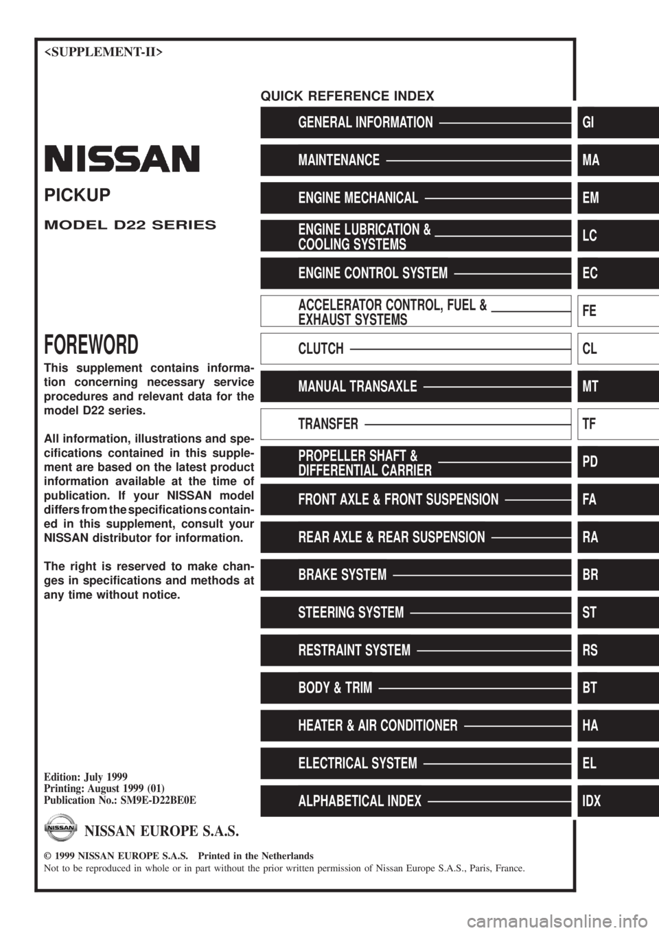
GENERAL INFORMATIONGI
MAINTENANCEMA
ENGINE MECHANICALEM
ENGINE LUBRICATION &
COOLING SYSTEMSLC
ENGINE CONTROL SYSTEMEC
ACCELERATOR CONTROL, FUEL &
EXHAUST SYSTEMSFE
CLUTCHCL
MANUAL TRANSAXLEMT
TRANSFERTF
PROPELLER SHAFT &
DIFFERENTIAL CARRIERPD
FRONT AXLE & FRONT SUSPENSIONFA
REAR AXLE & REAR SUSPENSIONRA
BRAKE SYSTEMBR
STEERING SYSTEMST
RESTRAINT SYSTEMRS
BODY & TRIMBT
HEATER & AIR CONDITIONERHA
ELECTRICAL SYSTEMEL
ALPHABETICAL INDEXIDX
PICKUP
MODEL D22 SERIES
FOREWORD
This supplement contains informa-
tion concerning necessary service
procedures and relevant data for the
model D22 series.
All information, illustrations and spe-
ci®cations contained in this supple-
ment are based on the latest product
information available at the time of
publication. If your NISSAN model
differs from the speci®cations contain-
ed in this supplement, consult your
NISSAN distributor for information.
The right is reserved to make chan-
ges in speci®cations and methods at
any time without notice.
Edition: July 1999
Printing: August 1999 (01)
Publication No.: SM9E-D22BE0E
NISSAN EUROPE S.A.S.
1999 NISSAN EUROPE S.A.S. Printed in the Netherlands
Not to be reproduced in whole or in part without the prior written permission of Nissan Europe S.A.S., Paris, France.
QUICK REFERENCE INDEX
Page 250 of 666
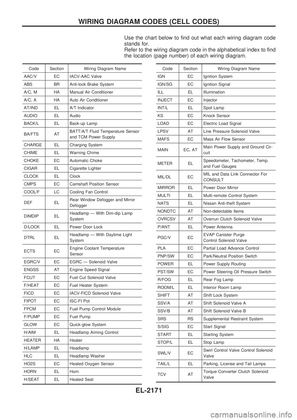
Use the chart below to find out what each wiring diagram code
stands for.
Refer to the wiring diagram code in the alphabetical index to find
the location (page number) of each wiring diagram.
Code Section Wiring Diagram Name
AAC/V EC IACV-AAC Valve
ABS BR Anti-lock Brake System
A/C, M HA Manual Air Conditioner
A/C, A HA Auto Air Conditioner
AT/IND EL A/T Indicator
AUDIO EL Audio
BACK/L EL Back-up Lamp
BA/FTS ATBATT/A/T Fluid Temperature Sensor
and TCM Power Supply
CHARGE EL Charging System
CHIME EL Warning Chime
CHOKE EC Automatic Choke
CIGAR EL Cigarette Lighter
CLOCK EL Clock
CMPS EC Camshaft Position Sensor
COOL/F LC Cooling Fan Control
DEF ELRear Window Defogger and Mirror
Defogger
DIMDIP ELHeadlamp Ð With Dim-dip Lamp
System
D/LOCK EL Power Door Lock
DTRL ELHeadlamp Ð With Daytime Light
System
ECTS ECEngine Coolant Temperature
Sensor
EGRC/V EC EGRC Ð Solenoid Valve
ENGSS AT Engine Speed Signal
FCUT EC Fuel Cut Solenoid Valve
F/HEAT EC Fuel Heater System
FICD EC IACV-FICD Solenoid Valve
FIPOT EC ISC-FI Pot
FPCM EC Fuel Pump Control Module
F/PUMP EC Fuel Pump
GLOW EC Quick-glow System
H/AIM EL Headlamp Aiming Control
HEATER HA Heater
H/LAMP EL Headlamp
HLC EL Headlamp Washer
HO2S EC Heated Oxygen Sensor
HORN EL Horn
H/SEAT EL Heated SeatCode Section Wiring Diagram Name
IGN EC Ignition System
IGN/SG EC Ignition Signal
ILL EL Illumination
INJECT EC Injector
INT/L EL Spot Lamp
KS EC Knock Sensor
LOAD EC Electric Load Signal
LPSV AT Line Pressure Solenoid Valve
MAFS EC Mass Air Flow Sensor
MAIN EC, ATMain Power Supply and Ground Cir-
cuit
METER ELSpeedometer, Tachometer, Temp.
and Fuel Gauges
MIL/DL ECMIL and Data Link Connector For
CONSULT
MIRROR EL Power Door Mirror
MULTI EL Multi-remote Control System
NATS EL Nissan Anti-theft System
NONDTC AT Non-detectable Items
OVRCSV AT Overrun Clutch Solenoid Valve
P/ANT EL Power Antenna
PGC/V ECEVAP Canister Purge
Control Solenoid Valve
PLA EC Partial Load Advance Control
PNP/SW EC Park/Neutral Position Switch
POWER EL Power Supply Routing
PST/SW EC Power Steering Oil Pressure Switch
R/FOG EL Rear Fog Lamp
ROOM/L EL Interior Room Lamp
SHIFT AT Shift Lock System
SSV/A AT Shift Solenoid Valve A
SSV/B AT Shift Solenoid Valve B
SRS RS Supplemental Restraint System
S/SIG EC Start Signal
START EL Starting System
STOP/L EL Stop Lamp
SWL/V ECSwirl Control Valve Control Solenoid
Valve
TAIL/L EL Parking, License and Tail Lamps
TCV ATTorque Converter Clutch Solenoid
Valve
WIRING DIAGRAM CODES (CELL CODES)
EL-2171
Page 422 of 666
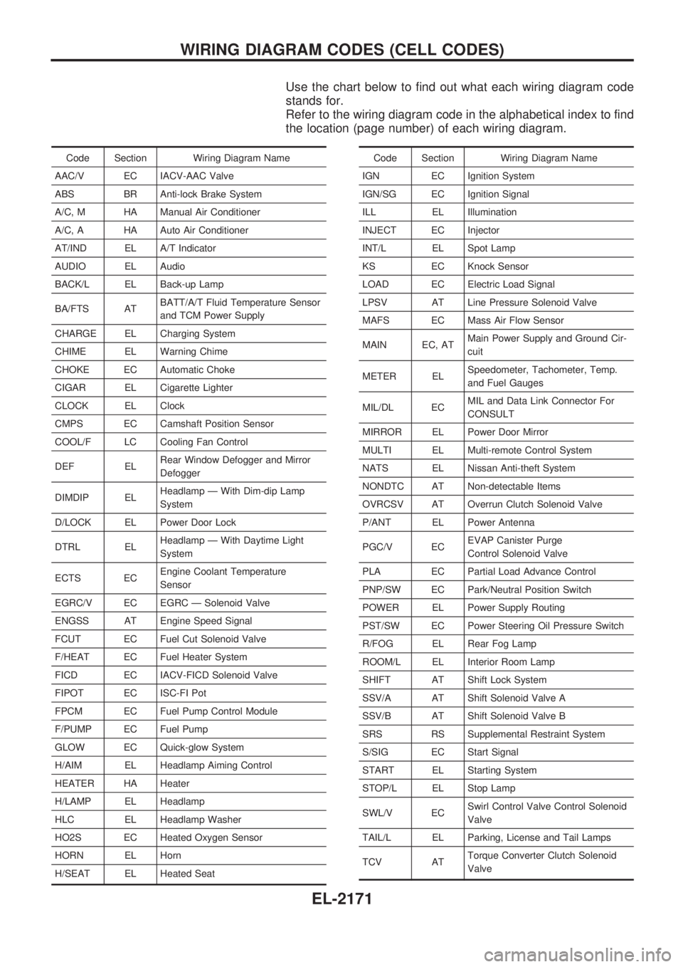
Use the chart below to find out what each wiring diagram code
stands for.
Refer to the wiring diagram code in the alphabetical index to find
the location (page number) of each wiring diagram.
Code Section Wiring Diagram Name
AAC/V EC IACV-AAC Valve
ABS BR Anti-lock Brake System
A/C, M HA Manual Air Conditioner
A/C, A HA Auto Air Conditioner
AT/IND EL A/T Indicator
AUDIO EL Audio
BACK/L EL Back-up Lamp
BA/FTS ATBATT/A/T Fluid Temperature Sensor
and TCM Power Supply
CHARGE EL Charging System
CHIME EL Warning Chime
CHOKE EC Automatic Choke
CIGAR EL Cigarette Lighter
CLOCK EL Clock
CMPS EC Camshaft Position Sensor
COOL/F LC Cooling Fan Control
DEF ELRear Window Defogger and Mirror
Defogger
DIMDIP ELHeadlamp Ð With Dim-dip Lamp
System
D/LOCK EL Power Door Lock
DTRL ELHeadlamp Ð With Daytime Light
System
ECTS ECEngine Coolant Temperature
Sensor
EGRC/V EC EGRC Ð Solenoid Valve
ENGSS AT Engine Speed Signal
FCUT EC Fuel Cut Solenoid Valve
F/HEAT EC Fuel Heater System
FICD EC IACV-FICD Solenoid Valve
FIPOT EC ISC-FI Pot
FPCM EC Fuel Pump Control Module
F/PUMP EC Fuel Pump
GLOW EC Quick-glow System
H/AIM EL Headlamp Aiming Control
HEATER HA Heater
H/LAMP EL Headlamp
HLC EL Headlamp Washer
HO2S EC Heated Oxygen Sensor
HORN EL Horn
H/SEAT EL Heated SeatCode Section Wiring Diagram Name
IGN EC Ignition System
IGN/SG EC Ignition Signal
ILL EL Illumination
INJECT EC Injector
INT/L EL Spot Lamp
KS EC Knock Sensor
LOAD EC Electric Load Signal
LPSV AT Line Pressure Solenoid Valve
MAFS EC Mass Air Flow Sensor
MAIN EC, ATMain Power Supply and Ground Cir-
cuit
METER ELSpeedometer, Tachometer, Temp.
and Fuel Gauges
MIL/DL ECMIL and Data Link Connector For
CONSULT
MIRROR EL Power Door Mirror
MULTI EL Multi-remote Control System
NATS EL Nissan Anti-theft System
NONDTC AT Non-detectable Items
OVRCSV AT Overrun Clutch Solenoid Valve
P/ANT EL Power Antenna
PGC/V ECEVAP Canister Purge
Control Solenoid Valve
PLA EC Partial Load Advance Control
PNP/SW EC Park/Neutral Position Switch
POWER EL Power Supply Routing
PST/SW EC Power Steering Oil Pressure Switch
R/FOG EL Rear Fog Lamp
ROOM/L EL Interior Room Lamp
SHIFT AT Shift Lock System
SSV/A AT Shift Solenoid Valve A
SSV/B AT Shift Solenoid Valve B
SRS RS Supplemental Restraint System
S/SIG EC Start Signal
START EL Starting System
STOP/L EL Stop Lamp
SWL/V ECSwirl Control Valve Control Solenoid
Valve
TAIL/L EL Parking, License and Tail Lamps
TCV ATTorque Converter Clutch Solenoid
Valve
WIRING DIAGRAM CODES (CELL CODES)
EL-2171
Page 501 of 666
HEATER&
AIR CONDITIONER
SECTION
HA
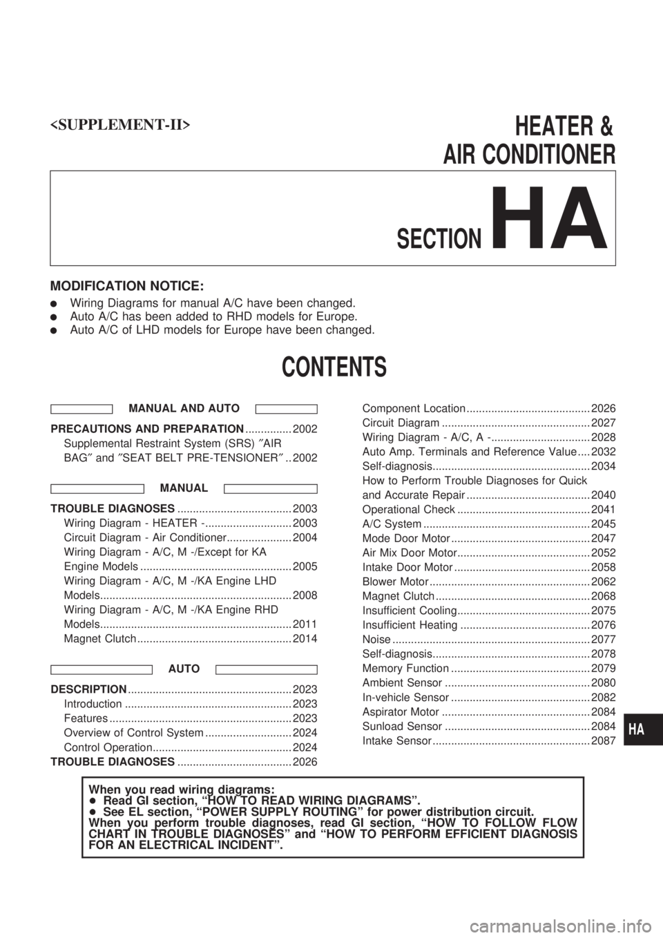
MODIFICATION NOTICE:
lWiring Diagrams for manual A/C have been changed.
lAuto A/C has been added to RHD models for Europe.
lAuto A/C of LHD models for Europe have been changed.
CONTENTS
MANUAL AND AUTO
PRECAUTIONS AND PREPARATION ............... 2002
Supplemental Restraint System (SRS) ²AIR
BAG ²and ²SEAT BELT PRE-TENSIONER ².. 2002
MANUAL
TROUBLE DIAGNOSES ..................................... 2003
Wiring Diagram - HEATER -............................ 2003
Circuit Diagram - Air Conditioner..................... 2004
Wiring Diagram - A/C, M -/Except for KA
Engine Models ................................................. 2005
Wiring Diagram - A/C, M -/KA Engine LHD
Models.............................................................. 2008
Wiring Diagram - A/C, M -/KA Engine RHD
Models.............................................................. 2011
Magnet Clutch .................................................. 2014
AUTO
DESCRIPTION..................................................... 2023
Introduction ...................................................... 2023
Features ........................................................... 2023
Overview of Control System ............................ 2024
Control Operation............................................. 2024
TROUBLE DIAGNOSES ..................................... 2026 Component Location ........................................ 2026
Circuit Diagram ................................................ 2027
Wiring Diagram - A/C, A -................................ 2028
Auto Amp. Terminals and Reference Value .... 2032
Self-diagnosis................................................... 2034
How to Perform Trouble Diagnoses for Quick
and Accurate Repair ........................................ 2040
Operational Check ........................................... 2041
A/C System ...................................................... 2045
Mode Door Motor ............................................. 2047
Air Mix Door Motor........................................... 2052
Intake Door Motor ............................................ 2058
Blower Motor .................................................... 2062
Magnet Clutch .................................................. 2068
Insufficient Cooling........................................... 2075
Insufficient Heating .......................................... 2076
Noise ................................................................ 2077
Self-diagnosis................................................... 2078
Memory Function ............................................. 2079
Ambient Sensor ............................................... 2080
In-vehicle Sensor ............................................. 2082
Aspirator Motor ................................................ 2084
Sunload Sensor ............................................... 2084
Intake Sensor ................................................... 2087
When you read wiring diagrams:
+
Read GI section, ªHOW TO READ WIRING DIAGRAMSº.
+ See EL section, ªPOWER SUPPLY ROUTINGº for power distribution circuit.
When you perform trouble diagnoses, read GI section, ªHOW TO FOLLOW FLOW
CHART IN TROUBLE DIAGNOSESº and ªHOW TO PERFORM EFFICIENT DIAGNOSIS
FOR AN ELECTRICAL INCIDENTº.
HA
Page 514 of 666
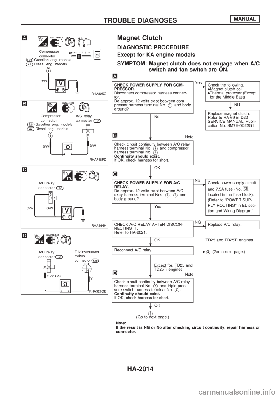
Magnet Clutch
DIAGNOSTIC PROCEDURE
Except for KA engine models
SYMPTOM: Magnet clutch does not engage when A/C
switch and fan switch are ON.
CHECK POWER SUPPLY FOR COM-
PRESSOR.
Disconnect compressor harness connec-
tor.
Do approx. 12 volts exist between com-
pressor harness terminal No.
V1and body
ground?
No
cYes
Check the following.
lMagnet clutch coillThermal protector (Except
for the Middle East)
NG
Replace magnet clutch.
Refer to HA-69 in D22
SERVICE MANUAL, Publi-
cation No. SM7E-0D22G1.
Note
Check circuit continuity between A/C relay
harness terminal No.
V5and compressor
harness terminal No.
V1.
Continuity should exist.
If OK, check harness for short.
OK
CHECK POWER SUPPLY FOR A/C
RELAY.
Do approx. 12 volts exist between A/C
relay harness terminal Nos.
V1,V3and
body ground?
Yes
cNo
Check power supply circuit
and 7.5A fuse (No.
23,
located in the fuse block).
(Refer to ªPOWER SUP-
PLY ROUTINGº in EL sec-
tion and Wiring Diagram.)
CHECK A/C RELAY AFTER DISCON-
NECTING IT.
Refer to HA-2021.
OK
cNG
Replace A/C relay.
TD25 and TD25Ti engines
Reconnect A/C relay.
cVA(Go to next page.)
Except for, TD25 and
TD25Ti engines
Note
Check circuit continuity between A/C relay
harness terminal No.
V2and triple-pres-
sure switch harness terminal No.
V4.
Continuity should exist.
If OK, check harness for short.
OK
VB(Go to next page.)
Note:
If the result is NG or No after checking circuit continuity, repair harness or
connector.
RHA325G
RHA748FD
RHA464H
RHA327GB
.
.
.
.
.
.
.
TROUBLE DIAGNOSESMANUAL
HA-2014
Page 515 of 666
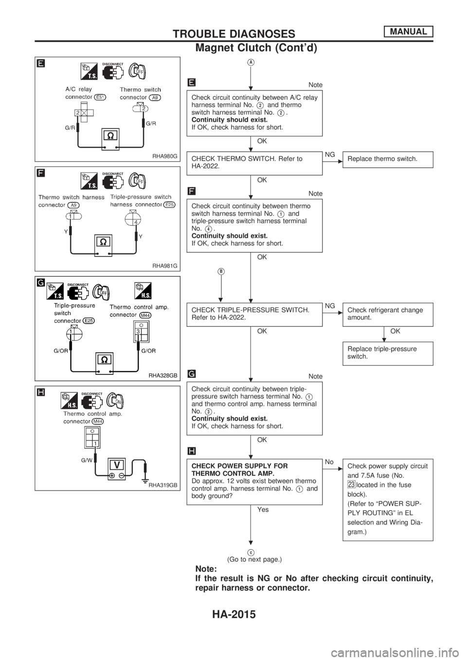
VA
Note
Check circuit continuity between A/C relay
harness terminal No.
V2and thermo
switch harness terminal No.
V2.
Continuity should exist.
If OK, check harness for short.
OK
CHECK THERMO SWITCH. Refer to
HA-2022.
OK
cNG
Replace thermo switch.
Note
Check circuit continuity between thermo
switch harness terminal No.
V1and
triple-pressure switch harness terminal
No.
V4.
Continuity should exist.
If OK, check harness for short.
OK
VB
.
CHECK TRIPLE-PRESSURE SWITCH.
Refer to HA-2022.
OK
cNG
Check refrigerant change
amount.
OK
Replace triple-pressure
switch.
Note
Check circuit continuity between triple-
pressure switch harness terminal No.
V1and thermo control amp. harness terminal
No.
V3.
Continuity should exist.
If OK, check harness for short.
OK
CHECK POWER SUPPLY FOR
THERMO CONTROL AMP.
Do approx. 12 volts exist between thermo
control amp. harness terminal No.
V1and
body ground?
Yes
cNo
Check power supply circuit
and 7.5A fuse (No.
23located in the fuse
block).
(Refer to ªPOWER SUP-
PLY ROUTINGº in EL
selection and Wiring Dia-
gram.)
Vc(Go to next page.)
Note:
If the result is NG or No after checking circuit continuity,
repair harness or connector.
RHA980G
RHA981G
RHA328GB
RHA319GB
.
.
.
.
.
.
.
.
TROUBLE DIAGNOSESMANUAL
Magnet Clutch (Cont'd)
HA-2015
Page 516 of 666
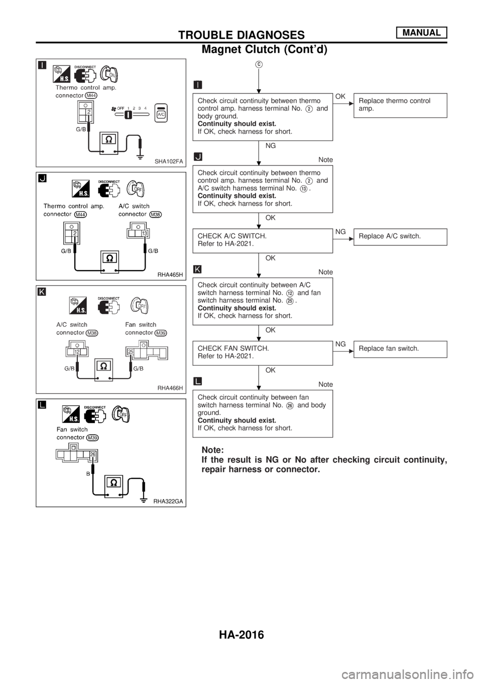
VC
Check circuit continuity between thermo
control amp. harness terminal No.
V2and
body ground.
Continuity should exist.
If OK, check harness for short.
NG
cOK
Replace thermo control
amp.
Note
Check circuit continuity between thermo
control amp. harness terminal No.
V2and
A/C switch harness terminal No.
V13.
Continuity should exist.
If OK, check harness for short.
OK
CHECK A/C SWITCH.
Refer to HA-2021.
OK
cNG
Replace A/C switch.
Note
Check circuit continuity between A/C
switch harness terminal No.
V12and fan
switch harness terminal No.
V25.
Continuity should exist.
If OK, check harness for short.
OK
CHECK FAN SWITCH.
Refer to HA-2021.
OK
cNG
Replace fan switch.
Note
Check circuit continuity between fan
switch harness terminal No.
V26and body
ground.
Continuity should exist.
If OK, check harness for short.
Note:
If the result is NG or No after checking circuit continuity,
repair harness or connector.
SHA102FA
RHA465H
RHA466H
RHA322GA
.
.
.
.
.
.
TROUBLE DIAGNOSESMANUAL
Magnet Clutch (Cont'd)
HA-2016
Page 517 of 666
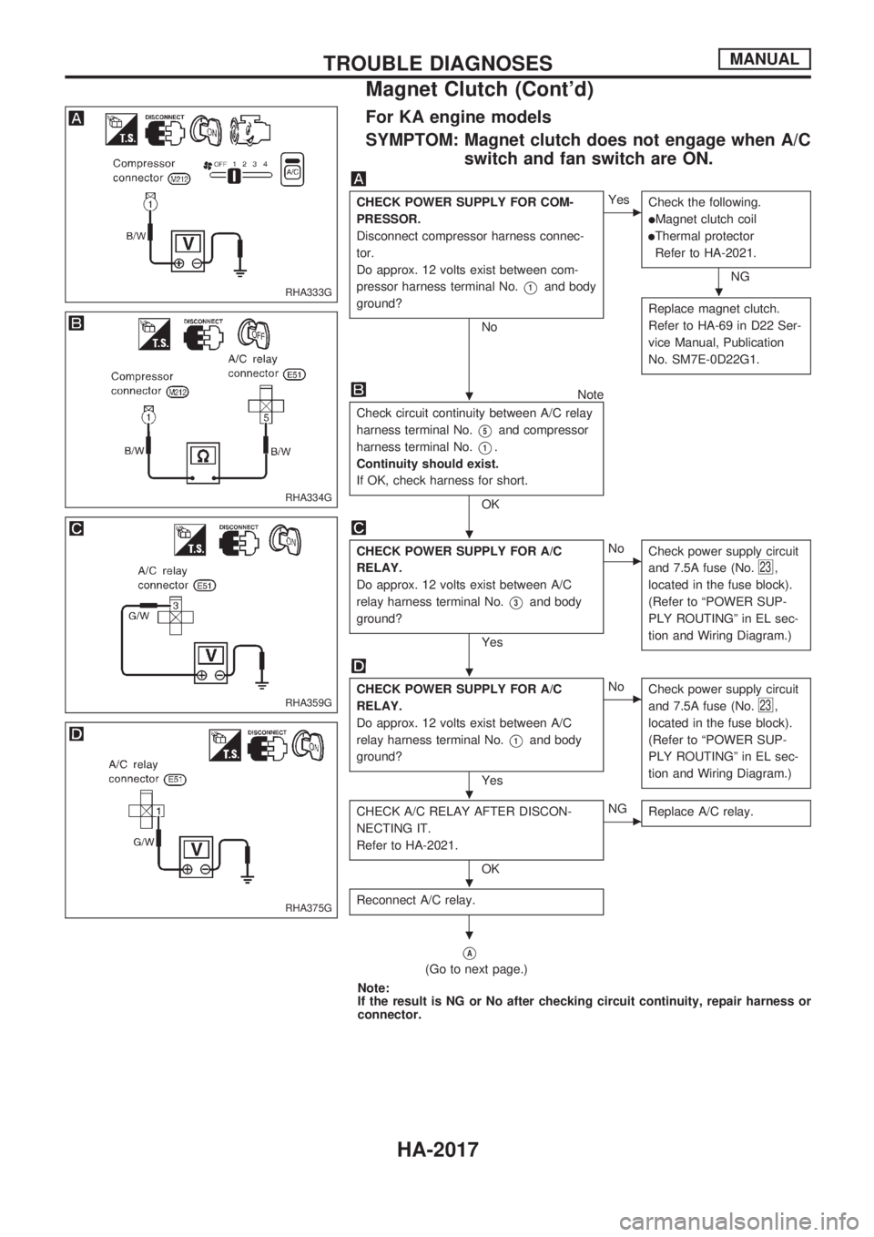
For KA engine models
SYMPTOM: Magnet clutch does not engage when A/C
switch and fan switch are ON.
CHECK POWER SUPPLY FOR COM-
PRESSOR.
Disconnect compressor harness connec-
tor.
Do approx. 12 volts exist between com-
pressor harness terminal No.
V1and body
ground?
No
cYes
Check the following.
lMagnet clutch coil
lThermal protector
Refer to HA-2021.
NG
Replace magnet clutch.
Refer to HA-69 in D22 Ser-
vice Manual, Publication
No. SM7E-0D22G1.
Note
Check circuit continuity between A/C relay
harness terminal No.
V5and compressor
harness terminal No.
V1.
Continuity should exist.
If OK, check harness for short.
OK
CHECK POWER SUPPLY FOR A/C
RELAY.
Do approx. 12 volts exist between A/C
relay harness terminal No.
V3and body
ground?
Yes
cNo
Check power supply circuit
and 7.5A fuse (No.
23,
located in the fuse block).
(Refer to ªPOWER SUP-
PLY ROUTINGº in EL sec-
tion and Wiring Diagram.)
CHECK POWER SUPPLY FOR A/C
RELAY.
Do approx. 12 volts exist between A/C
relay harness terminal No.
V1and body
ground?
Yes
cNo
Check power supply circuit
and 7.5A fuse (No.
23,
located in the fuse block).
(Refer to ªPOWER SUP-
PLY ROUTINGº in EL sec-
tion and Wiring Diagram.)
CHECK A/C RELAY AFTER DISCON-
NECTING IT.
Refer to HA-2021.
OK
cNG
Replace A/C relay.
Reconnect A/C relay.
VA
(Go to next page.)
Note:
If the result is NG or No after checking circuit continuity, repair harness or
connector.
RHA333G
RHA334G
RHA359G
RHA375G
.
.
.
.
.
.
.
TROUBLE DIAGNOSESMANUAL
Magnet Clutch (Cont'd)
HA-2017