1999 NISSAN PICK-UP relay
[x] Cancel search: relayPage 3 of 666
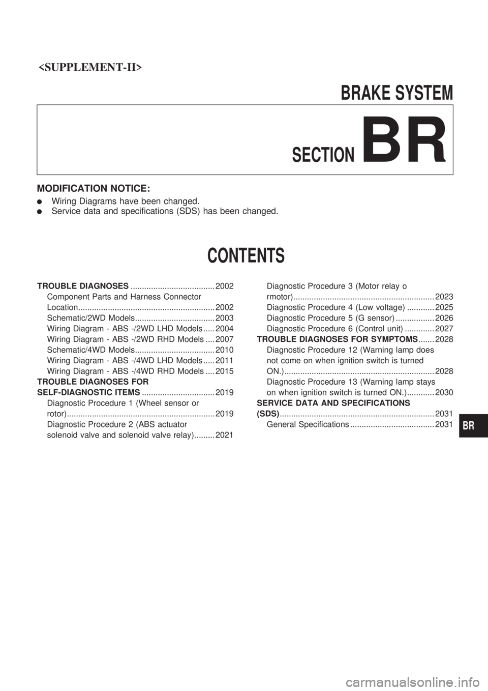
BRAKESYSTEM
SECTION
BR
MODIFICATION NOTICE:
lWiring Diagrams have been changed.
lService data and specifications (SDS) has been changed.
CONTENTS
TROUBLE DIAGNOSES ..................................... 2002
Component Parts and Harness Connector
Location............................................................ 2002
Schematic/2WD Models................................... 2003
Wiring Diagram - ABS -/2WD LHD Models ..... 2004
Wiring Diagram - ABS -/2WD RHD Models .... 2007
Schematic/4WD Models................................... 2010
Wiring Diagram - ABS -/4WD LHD Models ..... 2011
Wiring Diagram - ABS -/4WD RHD Models .... 2015
TROUBLE DIAGNOSES FOR
SELF-DIAGNOSTIC ITEMS ................................ 2019
Diagnostic Procedure 1 (Wheel sensor or
rotor)................................................................. 2019
Diagnostic Procedure 2 (ABS actuator
solenoid valve and solenoid valve relay)......... 2021 Diagnostic Procedure 3 (Motor relay o
rmotor).............................................................. 2023
Diagnostic Procedure 4 (Low voltage) ............ 2025
Diagnostic Procedure 5 (G sensor) ................. 2026
Diagnostic Procedure 6 (Control unit) ............. 2027
TROUBLE DIAGNOSES FOR SYMPTOMS ....... 2028
Diagnostic Procedure 12 (Warning lamp does
not come on when ignition switch is turned
ON.).................................................................. 2028
Diagnostic Procedure 13 (Warning lamp stays
on when ignition switch is turned ON.)............ 2030
SERVICE DATA AND SPECIFICATIONS
(SDS) .................................................................... 2031
General Specifications ..................................... 2031
BR
Page 23 of 666

Diagnostic Procedure 2 (ABS actuator
solenoid valve and solenoid valve relay)
Malfunction code No. 41, 45, 55, 42, 46, 56, 63
CHECK FUSIBLE LINK.
-------------------------------------------------------------------------------------------------------------------------------------------------------------------------------------------------------------------------------------------------------------------------------------------------------------
Check 30A fusible link
e
. For fusible link
layout, refer to POWER SUPPLY ROUT-
ING in EL section.
OK
cNG
VA(Go to next page.)
CHECK FUSE.
-------------------------------------------------------------------------------------------------------------------------------------------------------------------------------------------------------------------------------------------------------------------------------------------------------------
Check 10A fuse
18. For fuse layout, refer
to POWER SUPPLY ROUTING in EL
section.
OK
cNG
VB(Go to next page.)
CHECK CONNECTOR.
-------------------------------------------------------------------------------------------------------------------------------------------------------------------------------------------------------------------------------------------------------------------------------------------------------------
1. Disconnect ABS actuator and electric
unit connector. Check terminals for
damage or loose connection. Then
reconnect connector.
2. Carry out self-diagnosis again.
Does warning lamp activate again?
Yes
cNo
Inspection end
CHECK ABS ACTUATOR AND ELEC-
TRIC UNIT GROUND CIRCUIT.
-------------------------------------------------------------------------------------------------------------------------------------------------------------------------------------------------------------------------------------------------------------------------------------------------------------
Refer to ABS ACTUATOR AND ELEC-
TRIC UNIT GROUND in Ground Circuit
Check. Refer to original Service Manual.
OK
cNG
Repair harness and con-
nector.
CHECK SOLENOID VALVE RELAY
POWER SUPPLY CIRCUIT.
-------------------------------------------------------------------------------------------------------------------------------------------------------------------------------------------------------------------------------------------------------------------------------------------------------------
1. Disconnect ABS actuator and electric
unit connector.
2. Check voltage between ABS actuator
and electric unit connector
E4(body
side) terminal
V18and ground.
Battery voltage should exist.
OK
cNG
Check the following.
lHarness connectorE4
lHarness for open or
short between ABS
actuator and electric unit
and fusible link
If NG, repair harness or
connector.
REPLACE.
-------------------------------------------------------------------------------------------------------------------------------------------------------------------------------------------------------------------------------------------------------------------------------------------------------------
Replace ABS actuator and electric unit.
SBR050EA
SBR052E
.
.
.
.
.
TROUBLE DIAGNOSES FOR SELF-DIAGNOSTIC ITEMS
BR-2021
Page 24 of 666

VA
REPLACE.
-------------------------------------------------------------------------------------------------------------------------------------------------------------------------------------------------------------------------------------------------------------------------------------------------------------
Replace fusible link.
Does the fusible link blow out when
ignition switch is turned ªONº?
Yes
cNo
Inspection end
CHECK SOLENOID VALVE RELAY
POWER SUPPLY CIRCUIT.
-------------------------------------------------------------------------------------------------------------------------------------------------------------------------------------------------------------------------------------------------------------------------------------------------------------
1. Disconnect ABS actuator and electric
unit connector.
2. Check continuity between ABS actuator
and electric unit connector
E4(body
side) terminal
V18and ground.
Continuity should not exit.
OK
cNG
Check the following.
lHarness connectorE4
lHarness for open or short
between ABS actuator
and electric unit and
fusible link
If NG, repair harness or
connector.
REPLACE.
-------------------------------------------------------------------------------------------------------------------------------------------------------------------------------------------------------------------------------------------------------------------------------------------------------------
Replace ABS actuator and electric unit.
VB
REPLACE.
-------------------------------------------------------------------------------------------------------------------------------------------------------------------------------------------------------------------------------------------------------------------------------------------------------------
Replace fuse.
Does the fuse blow out when ignition
switch is turned ªONº?
No
cYes
Check the following.
lHarness connectorE4
lHarness for open or
short between ABS
actuator and electric unit
and fuse
If NG, repair harness or
connector.
END
-------------------------------------------------------------------------------------------------------------------------------------------------------------------------------------------------------------------------------------------------------------------------------------------------------------
INSPECTION END
SBR053E
.
.
.
.
.
TROUBLE DIAGNOSES FOR SELF-DIAGNOSTIC ITEMS
Diagnostic Procedure 2 (ABS actuator
solenoid valve and solenoid valve relay)
(Cont'd)
BR-2022
Page 25 of 666
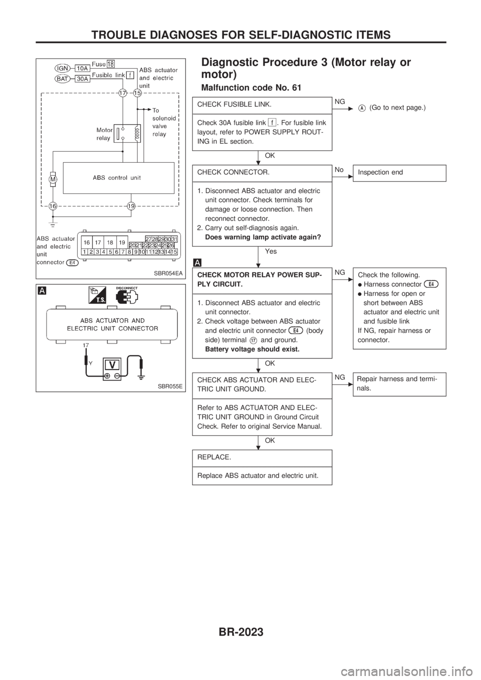
Diagnostic Procedure 3 (Motor relay or
motor)
Malfunction code No. 61
CHECK FUSIBLE LINK.
-------------------------------------------------------------------------------------------------------------------------------------------------------------------------------------------------------------------------------------------------------------------------------------------------------------
Check 30A fusible link
f . For fusible link
layout, refer to POWER SUPPLY ROUT-
ING in EL section.
OK
cNGVA(Go to next page.)
CHECK CONNECTOR.
-------------------------------------------------------------------------------------------------------------------------------------------------------------------------------------------------------------------------------------------------------------------------------------------------------------
1. Disconnect ABS actuator and electric
unit connector. Check terminals for
damage or loose connection. Then
reconnect connector.
2. Carry out self-diagnosis again.
Does warning lamp activate again?
Yes
cNo
Inspection end
CHECK MOTOR RELAY POWER SUP-
PLY CIRCUIT.
-------------------------------------------------------------------------------------------------------------------------------------------------------------------------------------------------------------------------------------------------------------------------------------------------------------
1. Disconnect ABS actuator and electric
unit connector.
2. Check voltage between ABS actuator
and electric unit connector
E4(body
side) terminal
V17and ground.
Battery voltage should exist.
OK
cNG
Check the following.
lHarness connectorE4
lHarness for open or
short between ABS
actuator and electric unit
and fusible link
If NG, repair harness or
connector.
CHECK ABS ACTUATOR AND ELEC-
TRIC UNIT GROUND.
-------------------------------------------------------------------------------------------------------------------------------------------------------------------------------------------------------------------------------------------------------------------------------------------------------------
Refer to ABS ACTUATOR AND ELEC-
TRIC UNIT GROUND in Ground Circuit
Check. Refer to original Service Manual.
OK
cNG
Repair harness and termi-
nals.
REPLACE.
-------------------------------------------------------------------------------------------------------------------------------------------------------------------------------------------------------------------------------------------------------------------------------------------------------------
Replace ABS actuator and electric unit.
SBR054EA
SBR055E
.
.
.
.
TROUBLE DIAGNOSES FOR SELF-DIAGNOSTIC ITEMS
BR-2023
Page 26 of 666
VA
REPLACE.
-------------------------------------------------------------------------------------------------------------------------------------------------------------------------------------------------------------------------------------------------------------------------------------------------------------
Replace fusible link.
Does the fusible link blow out when
ignition switch is turned ªONº?
Yes
cNo
Inspection end
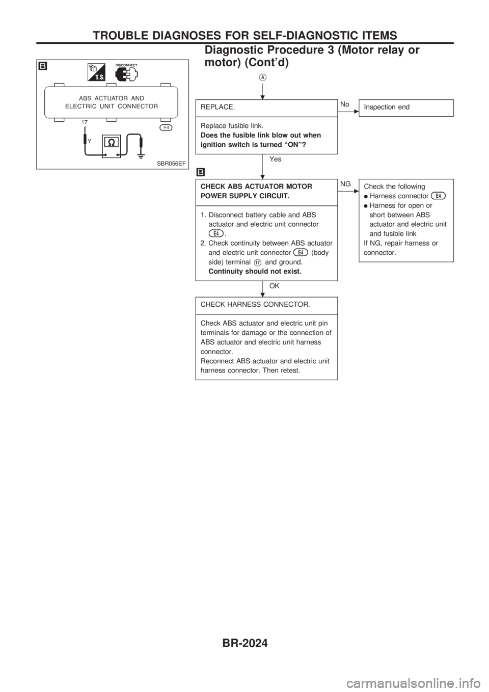
CHECK ABS ACTUATOR MOTOR
POWER SUPPLY CIRCUIT.
-------------------------------------------------------------------------------------------------------------------------------------------------------------------------------------------------------------------------------------------------------------------------------------------------------------
1. Disconnect battery cable and ABS
actuator and electric unit connector
E4.
2. Check continuity between ABS actuator
and electric unit connector
E4(body
side) terminal
V17and ground.
Continuity should not exist.
OK
cNG
Check the following
lHarness connectorE4
lHarness for open or
short between ABS
actuator and electric unit
and fusible link
If NG, repair harness or
connector.
CHECK HARNESS CONNECTOR.
-------------------------------------------------------------------------------------------------------------------------------------------------------------------------------------------------------------------------------------------------------------------------------------------------------------
Check ABS actuator and electric unit pin
terminals for damage or the connection of
ABS actuator and electric unit harness
connector.
Reconnect ABS actuator and electric unit
harness connector. Then retest.
SBR056EF
.
.
.
TROUBLE DIAGNOSES FOR SELF-DIAGNOSTIC ITEMS
Diagnostic Procedure 3 (Motor relay or
motor) (Cont'd)
BR-2024
Page 192 of 666
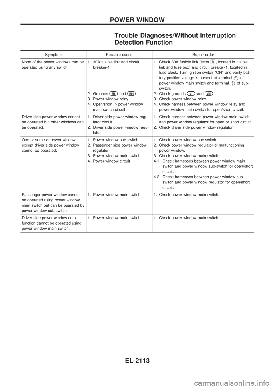
Trouble Diagnoses/Without Interruption
Detection Function
Symptom Possible cause Repair order
None of the power windows can be
operated using any switch.1. 30A fusible link and circuit
breaker-1
2. Grounds
M1andM54
3. Power window relay
4. Open/short in power window
main switch circuit1. Check 30A fusible link (letter
b, located in fusible
link and fuse box) and circuit breaker-1, located in
fuse block. Turn ignition switch ``ON'' and verify bat-
tery positive voltage is present at terminal
V1of
power window main switch and terminal
V5of sub-
switch.
2. Check grounds
M1andM54.
3. Check power window relay.
4. Check harness between power window relay and
power window main switch for open/short circuit.
Driver side power window cannot
be operated but other windows can
be operated.1. Driver side power window regu-
lator circuit
2. Driver side power window regu-
lator1. Check harness between power window main switch
and power window regulator for open or short circuit.
2. Check driver side power window regulator.
One or some of power window
except driver side power window
cannot be operated.1. Power window sub-switch
2. Passenger side power window
regulator
3. Power window main switch
4. Power window circuit1. Check power window sub-switch.
2. Check power window regulator of malfunctioning
power window.
3. Check power window main switch.
4-1. Check harnesses between power window main
switch and power window sub-switch for open/short
circuit.
4-2. Check harnesses between power window sub-
switch and power window regulator for open/short
circuit.
Passenger power window cannot
be operated using power window
main switch but can be operated by
power window sub-switch.1. Power window main switch 1. Check power window main switch.
Driver side power window auto
function cannot be operated using
power window main switch.1. Power window main switch 1. Check power window main switch.
POWER WINDOW
EL-2113
Page 208 of 666
System Description
FUNCTION
Multi-remote control system has the following function.
lDoor lock
lDoor unlock
lHazard reminder
LOCK OPERATION
To lock door by multi-remote controller, the following two signals must be received.
lKey switch OFF (when ignition key is not in ignition key cylinder.)
lAll door switches CLOSED
When the LOCK signal is input to multi-remote control unit (the antenna of the system is combined with
multi-remote control unit), ground is supplied
lthrough multi-remote control unit terminalV10
lto smart entrance control unit terminalV4and
lto door lock relay terminalV6.
Then smart entrance control unit operates to lock doors (except for driver's door) and door lock relay ener-
gized to lock driver's door.
UNLOCK OPERATION
To unlock door by multi-remote controller, the following signal must be received.
lKey switch OFF (when ignition key is not in ignition key cylinder)
When the UNLOCK signal is input to multi-remote control unit (the antenna of the system is combined with
multi-remote control unit), ground is supplied
lthrough multi-remote control unit terminalV11
lto smart entrance control unit terminalV5and
lto door lock relay terminalV5.
Then smart entrance control unit operates to unlock doors (except for driver's door) and door lock relay is
energized to unlock driver's door.
HAZARD REMINDER
When the doors and locked or unlocked by multi-remote controller, ground is supplied
lto terminalV1of multi-remote control relay-1 and 2
lthrough multi-remote control unit terminalV12.
Then the relays are energized and hazard warning lamp flashes as follows
lLock operation: Flash once
lUnlock operation: Flash twice
MULTI-REMOTE CONTROLLER ID CODE ENTRY
A maximum of four remote controllers can be entered. Any attempt to enter a remote controller will erase
all ID codes previously entered. Therefore, be sure to receive all remote controllers from the vehicle owner
when any ID code entry is performed.
To enter ID code entry, the following signals must be input to the multi-remote control unit.
lDriver side LOCKED signal (from driver side door unlock sensor)
lDoor switch CLOSED signal
lKey switch signal (INSERTED/WITHDRAWN)
lAccessory power supply
lSignal from remote controller
For detailed procedure, refer to ``ID Code Entry Procedure'' in EL-2139.
MULTI-REMOTE CONTROL SYSTEM
EL-2129
Page 214 of 666
Trouble Diagnoses
SYMPTOM CHART
Symptom Possible cause Diagnoses/service order
No doors can be locked or un-
locked by remote control opera-
tion. (See NOTE.)1. Remote controller battery
2. Key switch (insert)
3. Door switch
4. Power supply circuit for multi-
remote control unit
5. Ground circuit for multi-remote
control unit
6. Remote controller1. Check remote controller battery. Refer to EL-2136.
2. Check key switch (insert) signal at terminal
V7of
multi-remote control unit.
3. Check door switch signal at terminals
V1andV2
of multi-remote control unit.
4. Make sure battery voltage is present at terminal
V3of multi-remote control unit.
5. Check continuity between terminal
V5of multi-re-
mote control unit and ground.
6. Replace remote controller. Refer to EL-2139.
Driver's door cannot be locked or
unlocked by remote controller
operation.Driver side door lock actuator cir-
cuitCheck driver side door lock actuator circuit. Refer to
EL-2137.
Doors other than driver side cannot
be locked or unlocked by remote
control operation.
(If the power door lock system
does not operate correctly, check
power door lock system. Refer to
EL-2122.)Lock/unlock signal to smart
entrance control unit
lWhen locking is not possible:
Check continuity between terminal
V10of multi-remote
control unit and terminal
V4of smart entrance control
unit.
lWhen unlocking is not possible:
Check continuity between terminal
V11of multi-remote
control unit and terminal
V5of smart entrance control
unit.
Hazard reminder does not operate
properly.1. 10A fuse
2. Multi-remote control relay-1 and
2
3. Hazard reminder circuit1. Check 10A fuse (No.
5, located in the fuse block).
2. Check multi-remote control relay-1 and 2.
3. Check harness for open or short between relays and
multi-remote control unit terminal
V12.
The new ID of remote controller
cannot be entered.1. Remote controller battery
2. Key switch (insert)
3. Door switch
4. Driver's door unlock sensor
5. Accessory power supply circuit
for multi-remote control unit
6. Remote controller1. Check remote controller battery. Refer to EL-2136.
2. Check key switch (insert) signal at terminal
V7of
multi-remote control unit.
3. Check door switch signal at terminals
V1andV2of
multi-remote control unit.
4. Check driver's door unlock sensor signal at terminal
V6of multi-remote control unit.
5. Make sure battery voltage is present at terminal
V8
of multi-remote control unit while ignition switch is in
ACC position.
6. Replace remote controller. Refer to EL-2139.
Refer to ``MULTI-REMOTE CONTROL UNIT INSPECTION TABLE'' on next page to check the control unit
signals.
NOTE:
lAlways check remote controller battery before replacing remote controller.
lThe unlock operation of multi-remote control system does not activate with key inserted in the ignition
key cylinder.
lThe lock operation of multi-remote controller does not activate with the key inserted ignition key cylin-
der or if one of the door is opened.
MULTI-REMOTE CONTROL SYSTEM
EL-2135