Page 389 of 666
DOOR LOCK RELAY CHECK
ConditionContinuity between terminals
123456
Battery voltage not
applied between each
terminal
V3andV5jj
V3andV6jj
Battery voltage
applied between each
terminal
V3andV5jj
V3andV6jj
Alwaysjjj
CAUTION:
While applying battery voltage to relay terminals, insert fuse
into the circuit.
SEL411W
MULTI-REMOTE CONTROL SYSTEM
Trouble Diagnoses (Cont'd)
EL-2138
Page 514 of 666
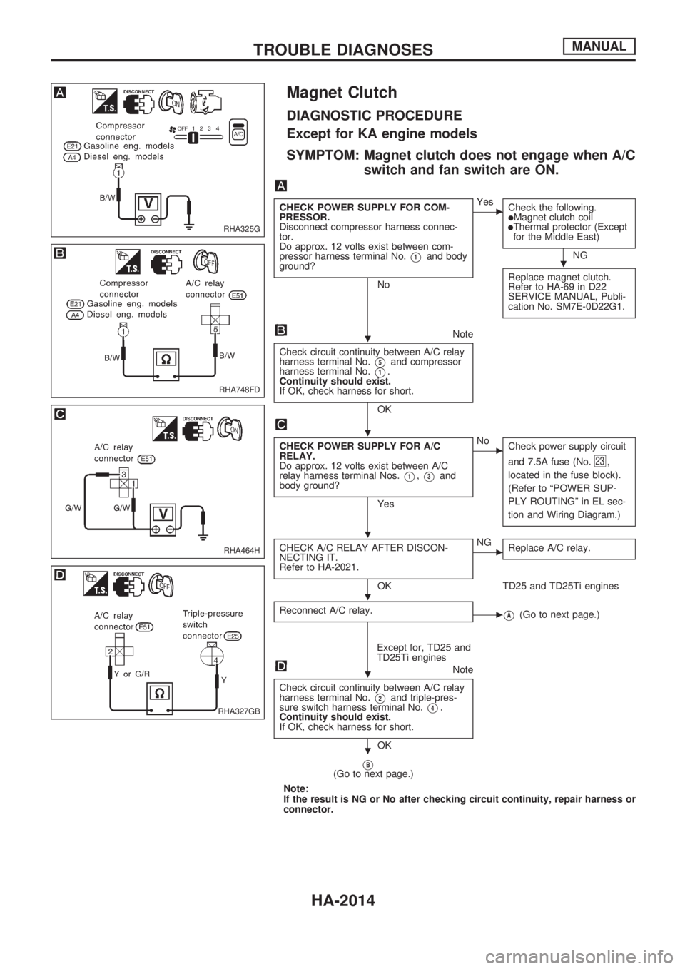
Magnet Clutch
DIAGNOSTIC PROCEDURE
Except for KA engine models
SYMPTOM: Magnet clutch does not engage when A/C
switch and fan switch are ON.
CHECK POWER SUPPLY FOR COM-
PRESSOR.
Disconnect compressor harness connec-
tor.
Do approx. 12 volts exist between com-
pressor harness terminal No.
V1and body
ground?
No
cYes
Check the following.
lMagnet clutch coillThermal protector (Except
for the Middle East)
NG
Replace magnet clutch.
Refer to HA-69 in D22
SERVICE MANUAL, Publi-
cation No. SM7E-0D22G1.
Note
Check circuit continuity between A/C relay
harness terminal No.
V5and compressor
harness terminal No.
V1.
Continuity should exist.
If OK, check harness for short.
OK
CHECK POWER SUPPLY FOR A/C
RELAY.
Do approx. 12 volts exist between A/C
relay harness terminal Nos.
V1,V3and
body ground?
Yes
cNo
Check power supply circuit
and 7.5A fuse (No.
23,
located in the fuse block).
(Refer to ªPOWER SUP-
PLY ROUTINGº in EL sec-
tion and Wiring Diagram.)
CHECK A/C RELAY AFTER DISCON-
NECTING IT.
Refer to HA-2021.
OK
cNG
Replace A/C relay.
TD25 and TD25Ti engines
Reconnect A/C relay.
cVA(Go to next page.)
Except for, TD25 and
TD25Ti engines
Note
Check circuit continuity between A/C relay
harness terminal No.
V2and triple-pres-
sure switch harness terminal No.
V4.
Continuity should exist.
If OK, check harness for short.
OK
VB(Go to next page.)
Note:
If the result is NG or No after checking circuit continuity, repair harness or
connector.
RHA325G
RHA748FD
RHA464H
RHA327GB
.
.
.
.
.
.
.
TROUBLE DIAGNOSESMANUAL
HA-2014
Page 515 of 666
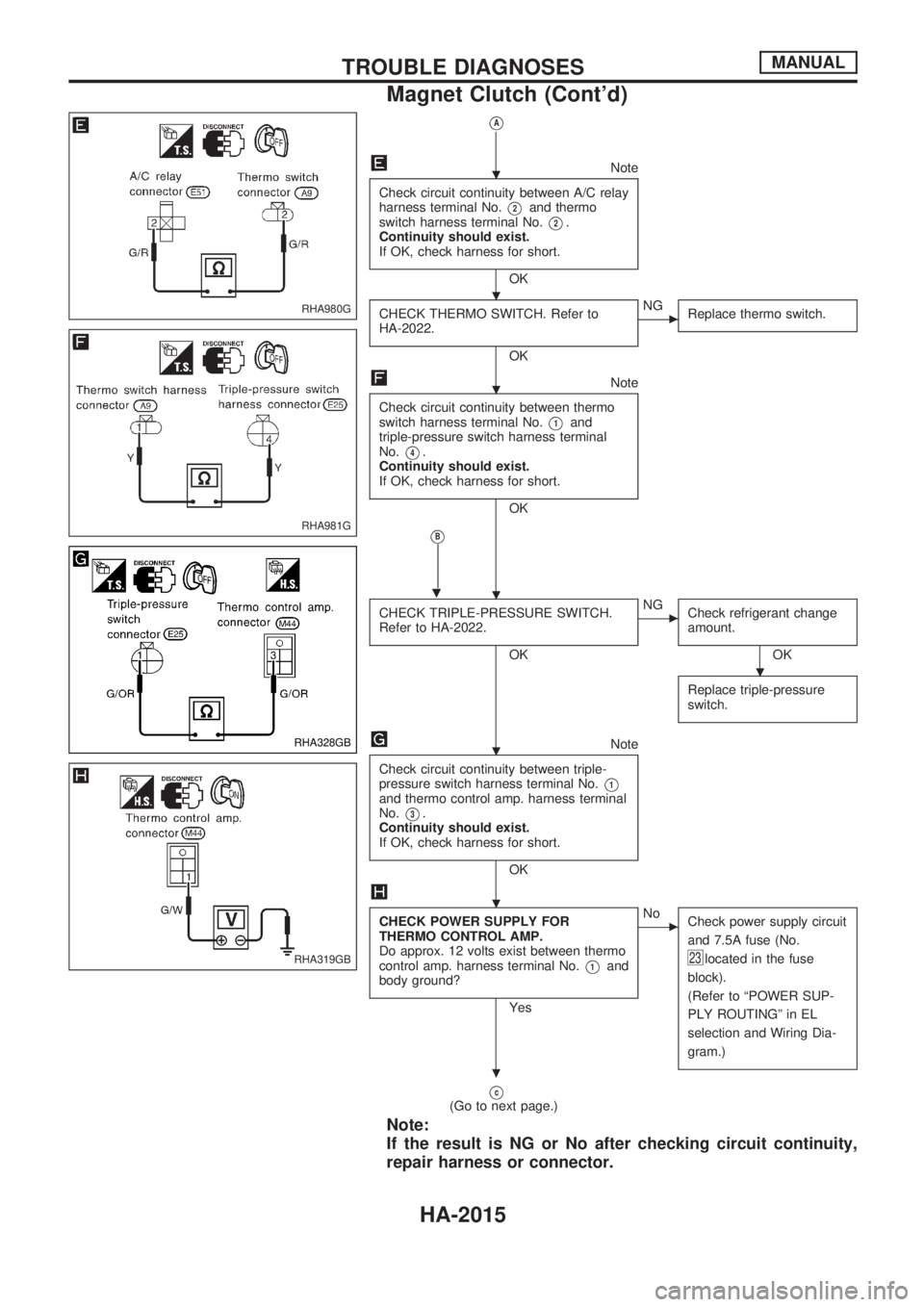
VA
Note
Check circuit continuity between A/C relay
harness terminal No.
V2and thermo
switch harness terminal No.
V2.
Continuity should exist.
If OK, check harness for short.
OK
CHECK THERMO SWITCH. Refer to
HA-2022.
OK
cNG
Replace thermo switch.
Note
Check circuit continuity between thermo
switch harness terminal No.
V1and
triple-pressure switch harness terminal
No.
V4.
Continuity should exist.
If OK, check harness for short.
OK
VB
.
CHECK TRIPLE-PRESSURE SWITCH.
Refer to HA-2022.
OK
cNG
Check refrigerant change
amount.
OK
Replace triple-pressure
switch.
Note
Check circuit continuity between triple-
pressure switch harness terminal No.
V1and thermo control amp. harness terminal
No.
V3.
Continuity should exist.
If OK, check harness for short.
OK
CHECK POWER SUPPLY FOR
THERMO CONTROL AMP.
Do approx. 12 volts exist between thermo
control amp. harness terminal No.
V1and
body ground?
Yes
cNo
Check power supply circuit
and 7.5A fuse (No.
23located in the fuse
block).
(Refer to ªPOWER SUP-
PLY ROUTINGº in EL
selection and Wiring Dia-
gram.)
Vc(Go to next page.)
Note:
If the result is NG or No after checking circuit continuity,
repair harness or connector.
RHA980G
RHA981G
RHA328GB
RHA319GB
.
.
.
.
.
.
.
.
TROUBLE DIAGNOSESMANUAL
Magnet Clutch (Cont'd)
HA-2015
Page 517 of 666
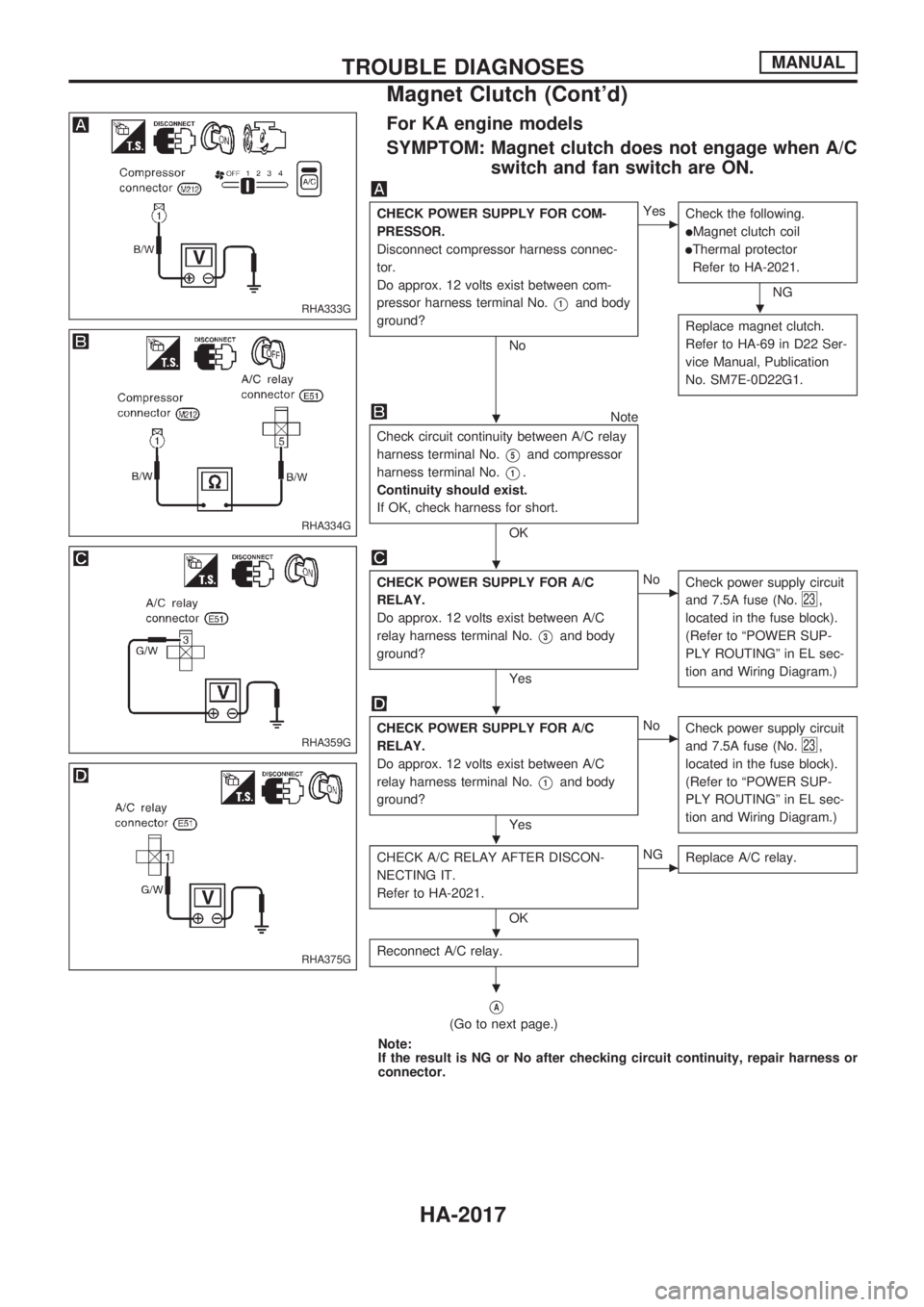
For KA engine models
SYMPTOM: Magnet clutch does not engage when A/C
switch and fan switch are ON.
CHECK POWER SUPPLY FOR COM-
PRESSOR.
Disconnect compressor harness connec-
tor.
Do approx. 12 volts exist between com-
pressor harness terminal No.
V1and body
ground?
No
cYes
Check the following.
lMagnet clutch coil
lThermal protector
Refer to HA-2021.
NG
Replace magnet clutch.
Refer to HA-69 in D22 Ser-
vice Manual, Publication
No. SM7E-0D22G1.
Note
Check circuit continuity between A/C relay
harness terminal No.
V5and compressor
harness terminal No.
V1.
Continuity should exist.
If OK, check harness for short.
OK
CHECK POWER SUPPLY FOR A/C
RELAY.
Do approx. 12 volts exist between A/C
relay harness terminal No.
V3and body
ground?
Yes
cNo
Check power supply circuit
and 7.5A fuse (No.
23,
located in the fuse block).
(Refer to ªPOWER SUP-
PLY ROUTINGº in EL sec-
tion and Wiring Diagram.)
CHECK POWER SUPPLY FOR A/C
RELAY.
Do approx. 12 volts exist between A/C
relay harness terminal No.
V1and body
ground?
Yes
cNo
Check power supply circuit
and 7.5A fuse (No.
23,
located in the fuse block).
(Refer to ªPOWER SUP-
PLY ROUTINGº in EL sec-
tion and Wiring Diagram.)
CHECK A/C RELAY AFTER DISCON-
NECTING IT.
Refer to HA-2021.
OK
cNG
Replace A/C relay.
Reconnect A/C relay.
VA
(Go to next page.)
Note:
If the result is NG or No after checking circuit continuity, repair harness or
connector.
RHA333G
RHA334G
RHA359G
RHA375G
.
.
.
.
.
.
.
TROUBLE DIAGNOSESMANUAL
Magnet Clutch (Cont'd)
HA-2017
Page 518 of 666
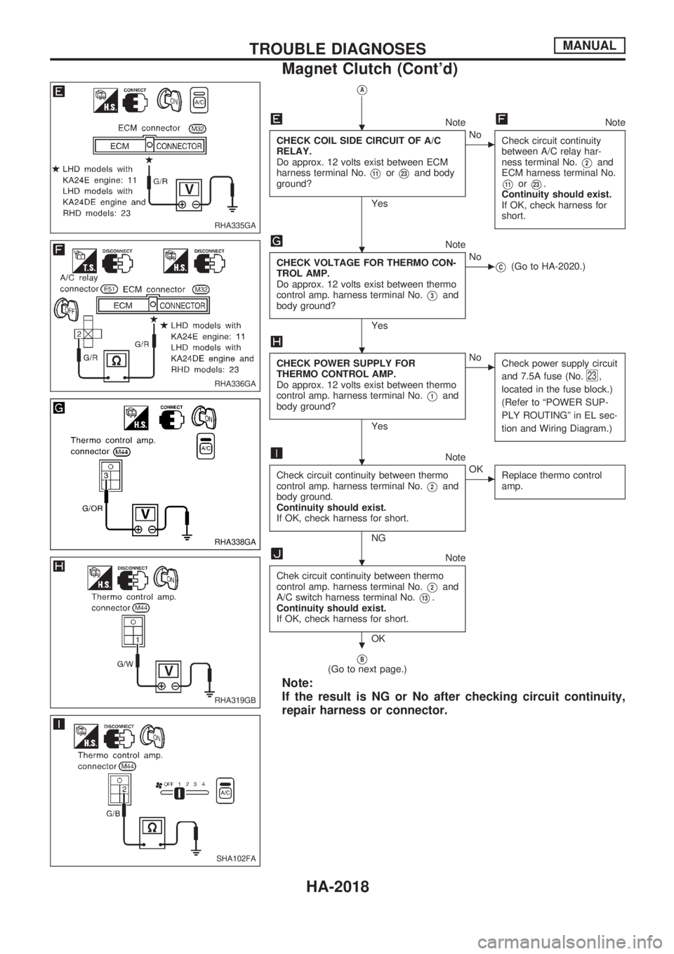
VA
NoteNote
CHECK COIL SIDE CIRCUIT OF A/C
RELAY.
Do approx. 12 volts exist between ECM
harness terminal No.
V11orV23and body
ground?
Yes
cNo
Check circuit continuity
between A/C relay har-
ness terminal No.
V2and
ECM harness terminal No.
V11orV23.
Continuity should exist.
If OK, check harness for
short.
Note
CHECK VOLTAGE FOR THERMO CON-
TROL AMP.
Do approx. 12 volts exist between thermo
control amp. harness terminal No.
V3and
body ground?
Yes
cNo
VC(Go to HA-2020.)
CHECK POWER SUPPLY FOR
THERMO CONTROL AMP.
Do approx. 12 volts exist between thermo
control amp. harness terminal No.
V1and
body ground?
Yes
cNo
Check power supply circuit
and 7.5A fuse (No.
23,
located in the fuse block.)
(Refer to ªPOWER SUP-
PLY ROUTINGº in EL sec-
tion and Wiring Diagram.)
Note
Check circuit continuity between thermo
control amp. harness terminal No.
V2and
body ground.
Continuity should exist.
If OK, check harness for short.
NG
cOK
Replace thermo control
amp.
Note
Chek circuit continuity between thermo
control amp. harness terminal No.
V2and
A/C switch harness terminal No.
V13.
Continuity should exist.
If OK, check harness for short.
OK
VB(Go to next page.)
Note:
If the result is NG or No after checking circuit continuity,
repair harness or connector.
RHA335GA
RHA336GA
RHA338GA
RHA319GB
SHA102FA
.
.
.
.
.
.
TROUBLE DIAGNOSESMANUAL
Magnet Clutch (Cont'd)
HA-2018
Page 521 of 666
ELECTRICAL COMPONENTS INSPECTION
Fan switch
Check continuity between terminals at each switch position.
Knob position Continuity between terminals
OFF
1
V24V26V25
2V23V26V25
3V22V26V25
4V21V26V25
A/C switch
Check continuity between terminals at each switch position.
Switch condition Terminal No.
Continuity
A/C
Å@
ON
V13V12Yes
OFF No
A/C relay
Check continuity between terminal Nos.V3andV5.
Conditions Continuity
12V direct current supply between terminal Nos.
V1andV2Yes
No current supply No
If NG, replace relay.
Thermal protector (For DKV-14C)
Temperature of compressor
ÉC (ÉF)Operation
Increasing to approx. 145 - 155 (293 - 311) Turn OFF
Decreasing to approx. 130 - 140 (266 - 284) Turn ON
SHA157F
RHA362GA
SEF090M
AHA849
TROUBLE DIAGNOSESMANUAL
Magnet Clutch (Cont'd)
HA-2021
Page 570 of 666
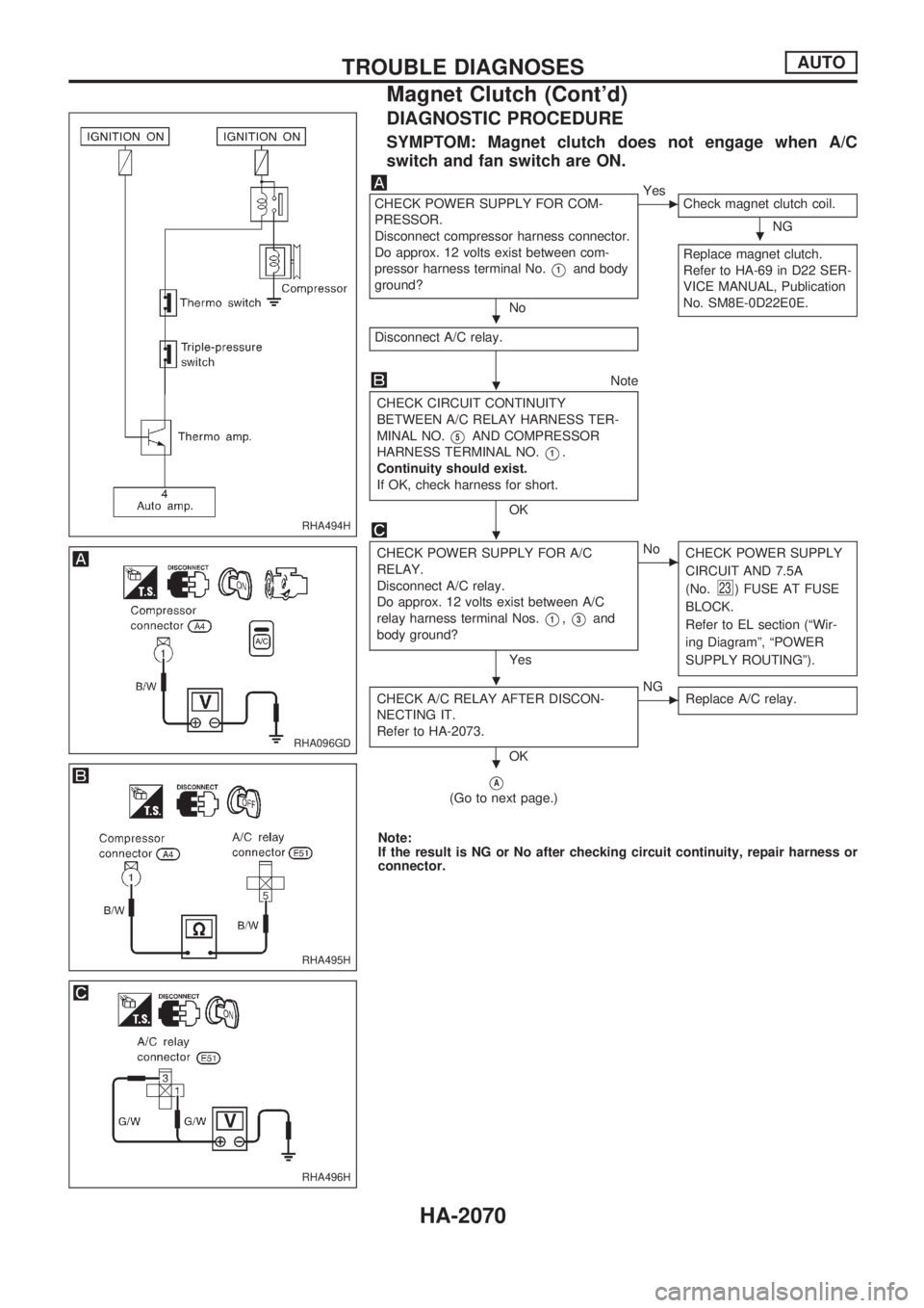
DIAGNOSTIC PROCEDURE
SYMPTOM: Magnet clutch does not engage when A/C
switch and fan switch are ON.
CHECK POWER SUPPLY FOR COM-
PRESSOR.
Disconnect compressor harness connector.
Do approx. 12 volts exist between com-
pressor harness terminal No.
V1and body
ground?
No
cYes
Check magnet clutch coil.
NG
Replace magnet clutch.
Refer to HA-69 in D22 SER-
VICE MANUAL, Publication
No. SM8E-0D22E0E.
Disconnect A/C relay.
Note
CHECK CIRCUIT CONTINUITY
BETWEEN A/C RELAY HARNESS TER-
MINAL NO.
V5AND COMPRESSOR
HARNESS TERMINAL NO.
V1.
Continuity should exist.
If OK, check harness for short.
OK
CHECK POWER SUPPLY FOR A/C
RELAY.
Disconnect A/C relay.
Do approx. 12 volts exist between A/C
relay harness terminal Nos.
V1,V3and
body ground?
Yes
cNo
CHECK POWER SUPPLY
CIRCUIT AND 7.5A
(No.
23) FUSE AT FUSE
BLOCK.
Refer to EL section (ªWir-
ing Diagramº, ªPOWER
SUPPLY ROUTINGº).
CHECK A/C RELAY AFTER DISCON-
NECTING IT.
Refer to HA-2073.
OK
cNG
Replace A/C relay.
VA
(Go to next page.)
Note:
If the result is NG or No after checking circuit continuity, repair harness or
connector.
RHA494H
RHA096GD
RHA495H
RHA496H
.
.
.
.
.
.
TROUBLE DIAGNOSESAUTO
Magnet Clutch (Cont'd)
HA-2070
Page 571 of 666
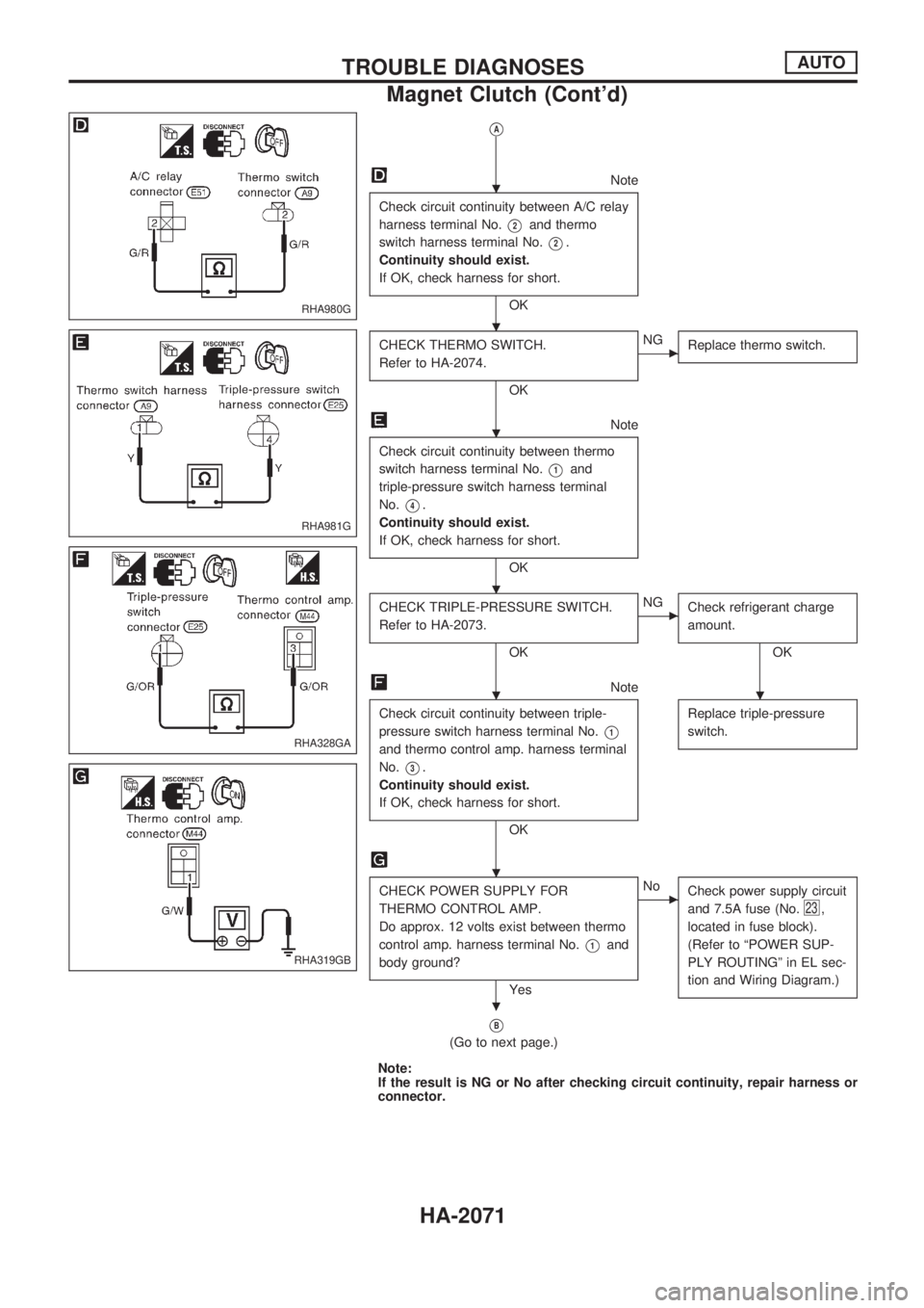
VA
Note
Check circuit continuity between A/C relay
harness terminal No.
V2and thermo
switch harness terminal No.
V2.
Continuity should exist.
If OK, check harness for short.
OK
CHECK THERMO SWITCH.
Refer to HA-2074.
OK
cNG
Replace thermo switch.
Note
Check circuit continuity between thermo
switch harness terminal No.
V1and
triple-pressure switch harness terminal
No.
V4.
Continuity should exist.
If OK, check harness for short.
OK
CHECK TRIPLE-PRESSURE SWITCH.
Refer to HA-2073.
OK
cNG
Check refrigerant charge
amount.
OK
Note
Check circuit continuity between triple-
pressure switch harness terminal No.
V1
and thermo control amp. harness terminal
No.
V3.
Continuity should exist.
If OK, check harness for short.
OKReplace triple-pressure
switch.
CHECK POWER SUPPLY FOR
THERMO CONTROL AMP.
Do approx. 12 volts exist between thermo
control amp. harness terminal No.
V1and
body ground?
Yes
cNo
Check power supply circuit
and 7.5A fuse (No.
23,
located in fuse block).
(Refer to ªPOWER SUP-
PLY ROUTINGº in EL sec-
tion and Wiring Diagram.)
VB
(Go to next page.)
Note:
If the result is NG or No after checking circuit continuity, repair harness or
connector.
RHA980G
RHA981G
RHA328GA
RHA319GB
.
.
.
.
..
.
.
TROUBLE DIAGNOSESAUTO
Magnet Clutch (Cont'd)
HA-2071