1999 NISSAN PICK-UP power steering
[x] Cancel search: power steeringPage 46 of 666
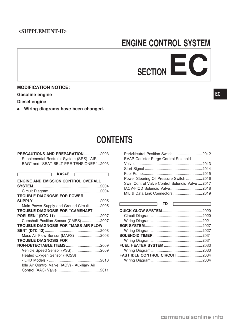
ENGINECONTROLSYSTEM
SECTION
EC
MODIFICATION NOTICE:
Gasoline engine
Diesel engine
lWiring diagrams have been changed.
CONTENTS
PRECAUTIONS AND PREPARATION ............... 2003
Supplemental Restraint System (SRS) ``AIR
BAG'' and ``SEAT BELT PRE-TENSIONER'' .. 2003
KA24E
ENGINE AND EMISSION CONTROL OVERALL
SYSTEM............................................................... 2004
Circuit Diagram ................................................ 2004
TROUBLE DIAGNOSIS FOR POWER
SUPPLY ............................................................... 2005
Main Power Supply and Ground Circuit .......... 2005
TROUBLE DIAGNOSIS FOR ``CAMSHAFT
POSI SEN'' (DTC 11) ........................................... 2007
Camshaft Position Sensor (CMPS) ................. 2007
TROUBLE DIAGNOSIS FOR ``MASS AIR FLOW
SEN'' (DTC 12) .................................................... 2008
Mass Air Flow Sensor (MAFS) ........................ 2008
TROUBLE DIAGNOSIS FOR
NON-DETECTABLE ITEMS ................................ 2009
Vehicle Speed Sensor (VSS) .......................... 2009
Heated Oxygen Sensor (HO2S)
- LHD Models - ................................................ 2010
Idle Air Control Valve (IACV) - Auxiliary Air
Control (AAC) Valve ........................................ 2011 Park/Neutral Position Switch ........................... 2012
EVAP Canister Purge Control Solenoid
Valve ................................................................ 2013
Start Signal ...................................................... 2014
Fuel Pump........................................................ 2015
Power Steering Oil Pressure Switch ............... 2016
Swirl Control Valve Control Solenoid Valve .... 2017
IACV-FICD Solenoid Valve .............................. 2018
MIL & Data Link Connectors ........................... 2019
TD
QUICK-GLOW SYSTEM ...................................... 2020
Circuit Diagram ................................................ 2020
Wiring Diagram ................................................ 2021
EGR SYSTEM ...................................................... 2027
Wiring Diagram ................................................ 2027
SOLENOID TIMER .............................................. 2031
Wiring Diagram ................................................ 2031
FUEL HEATER SYSTEM .................................... 2033
Wiring Diagram ................................................ 2033
FAST IDLE CONTROL CIRCUIT ........................ 2034
Wiring Diagram ................................................ 2034
EC
Page 61 of 666
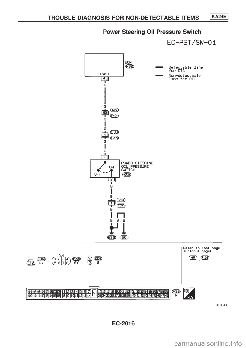
Power Steering Oil Pressure Switch
HEC643
TROUBLE DIAGNOSIS FOR NON-DETECTABLE ITEMSKA24E
EC-2016
Page 95 of 666
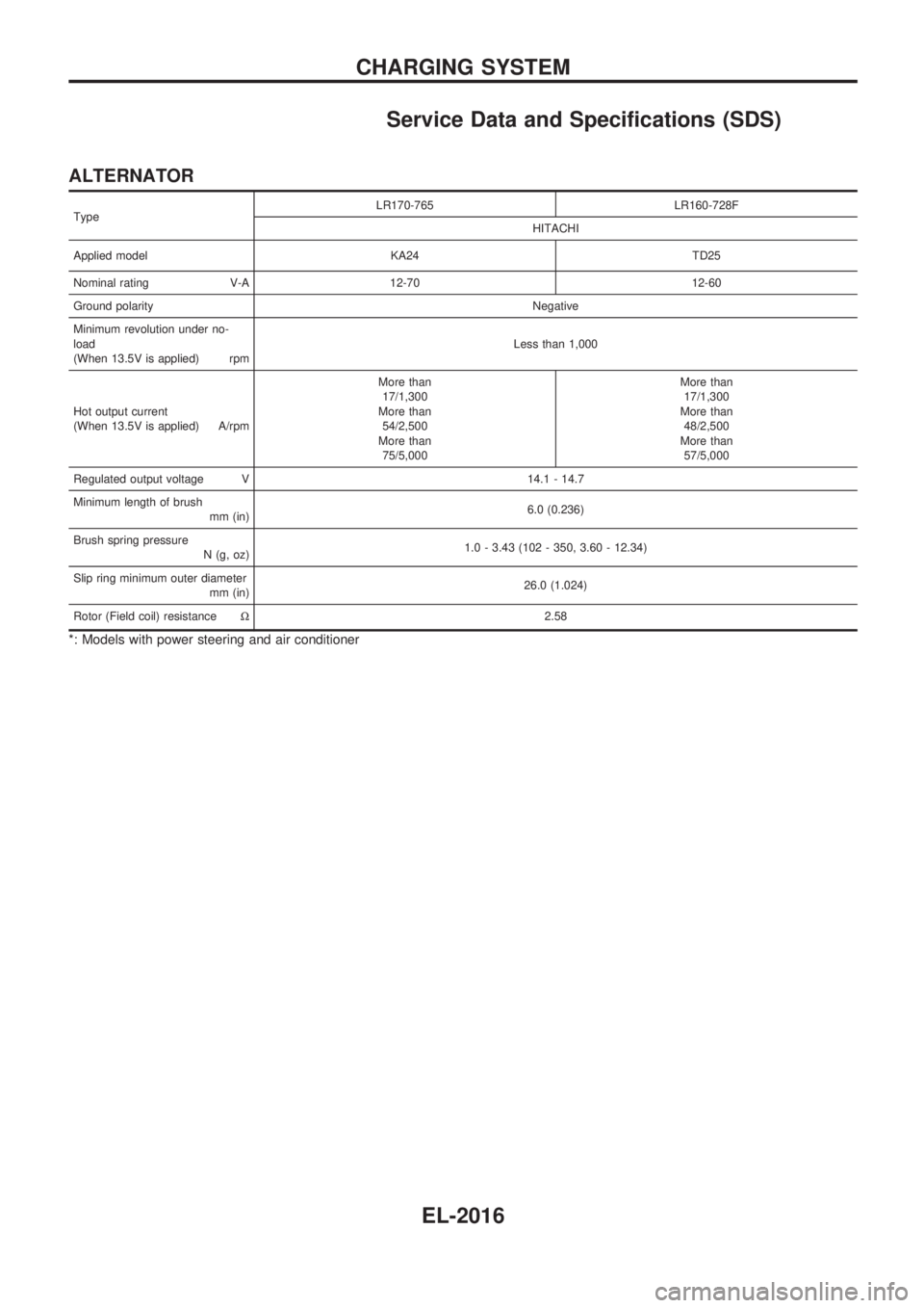
Service Data and Specifications (SDS)
ALTERNATOR
TypeLR170-765 LR160-728F
HITACHI
Applied model KA24 TD25
Nominal rating V-A 12-70 12-60
Ground polarityNegative
Minimum revolution under no-
load
(When 13.5V is applied) rpmLess than 1,000
Hot output current
(When 13.5V is applied) A/rpmMore than
17/1,300
More than
54/2,500
More than
75/5,000More than
17/1,300
More than
48/2,500
More than
57/5,000
Regulated output voltage V 14.1 - 14.7
Minimum length of brush
mm (in)6.0 (0.236)
Brush spring pressure
N (g, oz)1.0 - 3.43 (102 - 350, 3.60 - 12.34)
Slip ring minimum outer diameter
mm (in)26.0 (1.024)
Rotor (Field coil) resistanceW2.58
*: Models with power steering and air conditioner
CHARGING SYSTEM
EL-2016
Page 250 of 666
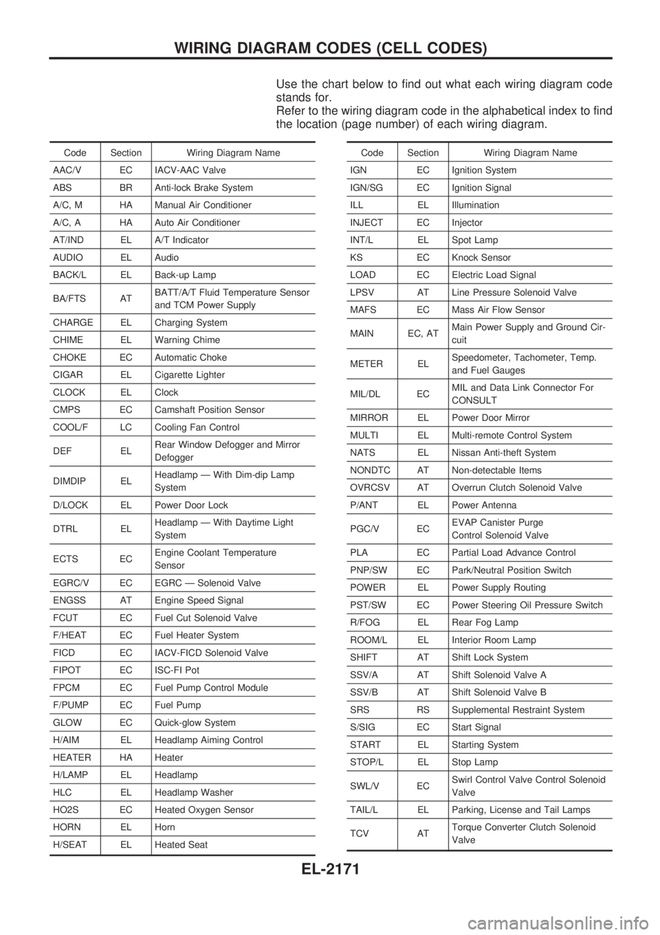
Use the chart below to find out what each wiring diagram code
stands for.
Refer to the wiring diagram code in the alphabetical index to find
the location (page number) of each wiring diagram.
Code Section Wiring Diagram Name
AAC/V EC IACV-AAC Valve
ABS BR Anti-lock Brake System
A/C, M HA Manual Air Conditioner
A/C, A HA Auto Air Conditioner
AT/IND EL A/T Indicator
AUDIO EL Audio
BACK/L EL Back-up Lamp
BA/FTS ATBATT/A/T Fluid Temperature Sensor
and TCM Power Supply
CHARGE EL Charging System
CHIME EL Warning Chime
CHOKE EC Automatic Choke
CIGAR EL Cigarette Lighter
CLOCK EL Clock
CMPS EC Camshaft Position Sensor
COOL/F LC Cooling Fan Control
DEF ELRear Window Defogger and Mirror
Defogger
DIMDIP ELHeadlamp Ð With Dim-dip Lamp
System
D/LOCK EL Power Door Lock
DTRL ELHeadlamp Ð With Daytime Light
System
ECTS ECEngine Coolant Temperature
Sensor
EGRC/V EC EGRC Ð Solenoid Valve
ENGSS AT Engine Speed Signal
FCUT EC Fuel Cut Solenoid Valve
F/HEAT EC Fuel Heater System
FICD EC IACV-FICD Solenoid Valve
FIPOT EC ISC-FI Pot
FPCM EC Fuel Pump Control Module
F/PUMP EC Fuel Pump
GLOW EC Quick-glow System
H/AIM EL Headlamp Aiming Control
HEATER HA Heater
H/LAMP EL Headlamp
HLC EL Headlamp Washer
HO2S EC Heated Oxygen Sensor
HORN EL Horn
H/SEAT EL Heated SeatCode Section Wiring Diagram Name
IGN EC Ignition System
IGN/SG EC Ignition Signal
ILL EL Illumination
INJECT EC Injector
INT/L EL Spot Lamp
KS EC Knock Sensor
LOAD EC Electric Load Signal
LPSV AT Line Pressure Solenoid Valve
MAFS EC Mass Air Flow Sensor
MAIN EC, ATMain Power Supply and Ground Cir-
cuit
METER ELSpeedometer, Tachometer, Temp.
and Fuel Gauges
MIL/DL ECMIL and Data Link Connector For
CONSULT
MIRROR EL Power Door Mirror
MULTI EL Multi-remote Control System
NATS EL Nissan Anti-theft System
NONDTC AT Non-detectable Items
OVRCSV AT Overrun Clutch Solenoid Valve
P/ANT EL Power Antenna
PGC/V ECEVAP Canister Purge
Control Solenoid Valve
PLA EC Partial Load Advance Control
PNP/SW EC Park/Neutral Position Switch
POWER EL Power Supply Routing
PST/SW EC Power Steering Oil Pressure Switch
R/FOG EL Rear Fog Lamp
ROOM/L EL Interior Room Lamp
SHIFT AT Shift Lock System
SSV/A AT Shift Solenoid Valve A
SSV/B AT Shift Solenoid Valve B
SRS RS Supplemental Restraint System
S/SIG EC Start Signal
START EL Starting System
STOP/L EL Stop Lamp
SWL/V ECSwirl Control Valve Control Solenoid
Valve
TAIL/L EL Parking, License and Tail Lamps
TCV ATTorque Converter Clutch Solenoid
Valve
WIRING DIAGRAM CODES (CELL CODES)
EL-2171
Page 267 of 666
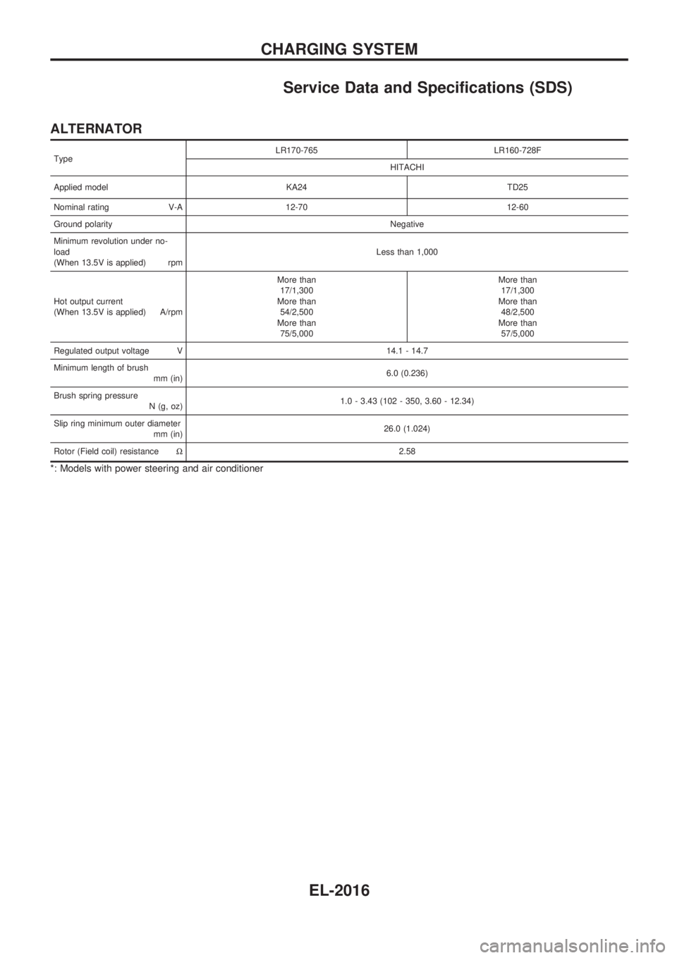
Service Data and Specifications (SDS)
ALTERNATOR
TypeLR170-765 LR160-728F
HITACHI
Applied model KA24 TD25
Nominal rating V-A 12-70 12-60
Ground polarityNegative
Minimum revolution under no-
load
(When 13.5V is applied) rpmLess than 1,000
Hot output current
(When 13.5V is applied) A/rpmMore than
17/1,300
More than
54/2,500
More than
75/5,000More than
17/1,300
More than
48/2,500
More than
57/5,000
Regulated output voltage V 14.1 - 14.7
Minimum length of brush
mm (in)6.0 (0.236)
Brush spring pressure
N (g, oz)1.0 - 3.43 (102 - 350, 3.60 - 12.34)
Slip ring minimum outer diameter
mm (in)26.0 (1.024)
Rotor (Field coil) resistanceW2.58
*: Models with power steering and air conditioner
CHARGING SYSTEM
EL-2016
Page 422 of 666
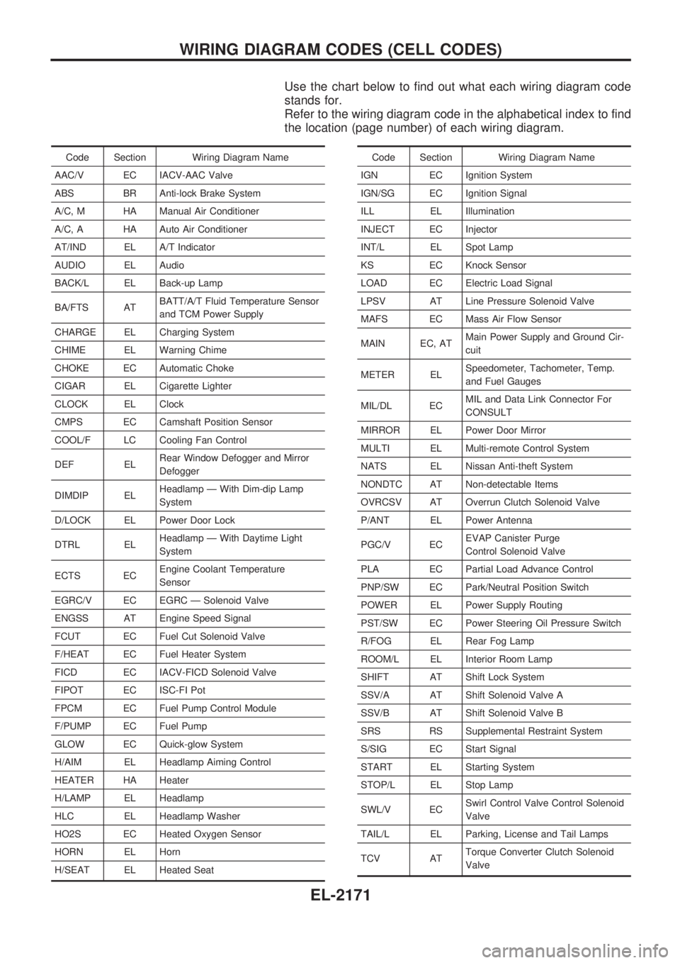
Use the chart below to find out what each wiring diagram code
stands for.
Refer to the wiring diagram code in the alphabetical index to find
the location (page number) of each wiring diagram.
Code Section Wiring Diagram Name
AAC/V EC IACV-AAC Valve
ABS BR Anti-lock Brake System
A/C, M HA Manual Air Conditioner
A/C, A HA Auto Air Conditioner
AT/IND EL A/T Indicator
AUDIO EL Audio
BACK/L EL Back-up Lamp
BA/FTS ATBATT/A/T Fluid Temperature Sensor
and TCM Power Supply
CHARGE EL Charging System
CHIME EL Warning Chime
CHOKE EC Automatic Choke
CIGAR EL Cigarette Lighter
CLOCK EL Clock
CMPS EC Camshaft Position Sensor
COOL/F LC Cooling Fan Control
DEF ELRear Window Defogger and Mirror
Defogger
DIMDIP ELHeadlamp Ð With Dim-dip Lamp
System
D/LOCK EL Power Door Lock
DTRL ELHeadlamp Ð With Daytime Light
System
ECTS ECEngine Coolant Temperature
Sensor
EGRC/V EC EGRC Ð Solenoid Valve
ENGSS AT Engine Speed Signal
FCUT EC Fuel Cut Solenoid Valve
F/HEAT EC Fuel Heater System
FICD EC IACV-FICD Solenoid Valve
FIPOT EC ISC-FI Pot
FPCM EC Fuel Pump Control Module
F/PUMP EC Fuel Pump
GLOW EC Quick-glow System
H/AIM EL Headlamp Aiming Control
HEATER HA Heater
H/LAMP EL Headlamp
HLC EL Headlamp Washer
HO2S EC Heated Oxygen Sensor
HORN EL Horn
H/SEAT EL Heated SeatCode Section Wiring Diagram Name
IGN EC Ignition System
IGN/SG EC Ignition Signal
ILL EL Illumination
INJECT EC Injector
INT/L EL Spot Lamp
KS EC Knock Sensor
LOAD EC Electric Load Signal
LPSV AT Line Pressure Solenoid Valve
MAFS EC Mass Air Flow Sensor
MAIN EC, ATMain Power Supply and Ground Cir-
cuit
METER ELSpeedometer, Tachometer, Temp.
and Fuel Gauges
MIL/DL ECMIL and Data Link Connector For
CONSULT
MIRROR EL Power Door Mirror
MULTI EL Multi-remote Control System
NATS EL Nissan Anti-theft System
NONDTC AT Non-detectable Items
OVRCSV AT Overrun Clutch Solenoid Valve
P/ANT EL Power Antenna
PGC/V ECEVAP Canister Purge
Control Solenoid Valve
PLA EC Partial Load Advance Control
PNP/SW EC Park/Neutral Position Switch
POWER EL Power Supply Routing
PST/SW EC Power Steering Oil Pressure Switch
R/FOG EL Rear Fog Lamp
ROOM/L EL Interior Room Lamp
SHIFT AT Shift Lock System
SSV/A AT Shift Solenoid Valve A
SSV/B AT Shift Solenoid Valve B
SRS RS Supplemental Restraint System
S/SIG EC Start Signal
START EL Starting System
STOP/L EL Stop Lamp
SWL/V ECSwirl Control Valve Control Solenoid
Valve
TAIL/L EL Parking, License and Tail Lamps
TCV ATTorque Converter Clutch Solenoid
Valve
WIRING DIAGRAM CODES (CELL CODES)
EL-2171
Page 443 of 666
Removal
CAUTION:
lAfter removing the timing chain, do not turn crankshaft
and camshaft separately, or valves will strike piston
heads.
lWhen installing chain tensioners or other sliding parts,
lubricate contacting surfaces with new engine oil.
lApply new engine oil to bolt threads and seat surfaces
when installing camshaft sprockets and crankshaft pul-
ley.
lDo not spill engine coolant on drive belts.
UPPER TIMING CHAIN
1. Remove air duct assembly.
2. Remove vacuum hoses, electrical harness connectors and
harness clamps.
3. Remove power steering drive belt.
4. Remove power steering pump and position it to one side.
5. Remove power steering pump bracket.
6. Remove idler pulley and bracket as well.
7. Remove ignition wires and spark plugs.
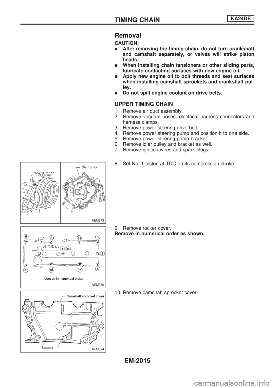
8. Set No. 1 piston at TDC on its compression stroke.
9. Remove rocker cover.
Remove in numerical order as shown.
10. Remove camshaft sprocket cover.
AEM373
AEM356
AEM374
TIMING CHAINKA24DE
EM-2015
Page 464 of 666
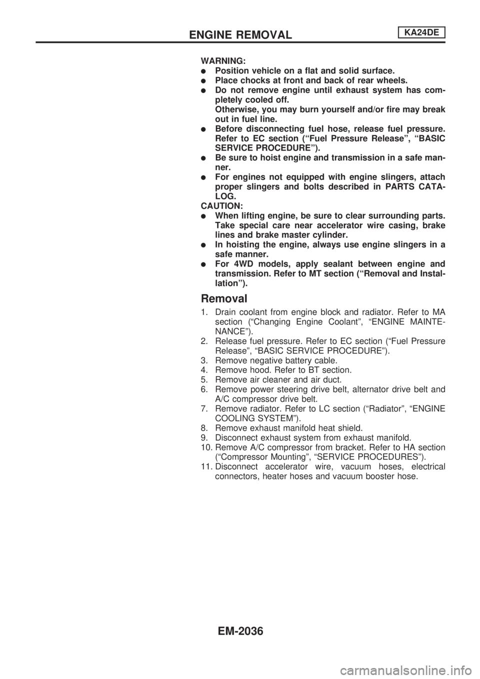
WARNING:
lPosition vehicle on a flat and solid surface.
lPlace chocks at front and back of rear wheels.
lDo not remove engine until exhaust system has com-
pletely cooled off.
Otherwise, you may burn yourself and/or fire may break
out in fuel line.
lBefore disconnecting fuel hose, release fuel pressure.
Refer to EC section (ªFuel Pressure Releaseº, ªBASIC
SERVICE PROCEDUREº).
lBe sure to hoist engine and transmission in a safe man-
ner.
lFor engines not equipped with engine slingers, attach
proper slingers and bolts described in PARTS CATA-
LOG.
CAUTION:
lWhen lifting engine, be sure to clear surrounding parts.
Take special care near accelerator wire casing, brake
lines and brake master cylinder.
lIn hoisting the engine, always use engine slingers in a
safe manner.
lFor 4WD models, apply sealant between engine and
transmission. Refer to MT section (ªRemoval and Instal-
lationº).
Removal
1. Drain coolant from engine block and radiator. Refer to MA
section (ªChanging Engine Coolantº, ªENGINE MAINTE-
NANCEº).
2. Release fuel pressure. Refer to EC section (ªFuel Pressure
Releaseº, ªBASIC SERVICE PROCEDUREº).
3. Remove negative battery cable.
4. Remove hood. Refer to BT section.
5. Remove air cleaner and air duct.
6. Remove power steering drive belt, alternator drive belt and
A/C compressor drive belt.
7. Remove radiator. Refer to LC section (ªRadiatorº, ªENGINE
COOLING SYSTEMº).
8. Remove exhaust manifold heat shield.
9. Disconnect exhaust system from exhaust manifold.
10. Remove A/C compressor from bracket. Refer to HA section
(ªCompressor Mountingº, ªSERVICE PROCEDURESº).
11. Disconnect accelerator wire, vacuum hoses, electrical
connectors, heater hoses and vacuum booster hose.
ENGINE REMOVALKA24DE
EM-2036