1999 NISSAN PICK-UP IGNITION
[x] Cancel search: IGNITIONPage 3 of 666

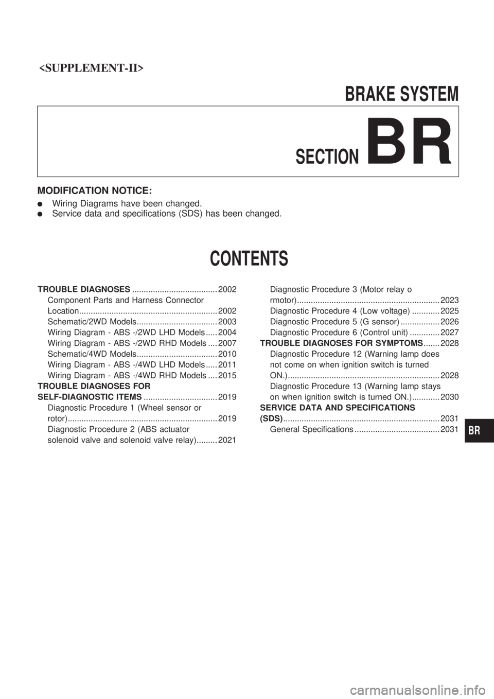
BRAKESYSTEM
SECTION
BR
MODIFICATION NOTICE:
lWiring Diagrams have been changed.
lService data and specifications (SDS) has been changed.
CONTENTS
TROUBLE DIAGNOSES ..................................... 2002
Component Parts and Harness Connector
Location............................................................ 2002
Schematic/2WD Models................................... 2003
Wiring Diagram - ABS -/2WD LHD Models ..... 2004
Wiring Diagram - ABS -/2WD RHD Models .... 2007
Schematic/4WD Models................................... 2010
Wiring Diagram - ABS -/4WD LHD Models ..... 2011
Wiring Diagram - ABS -/4WD RHD Models .... 2015
TROUBLE DIAGNOSES FOR
SELF-DIAGNOSTIC ITEMS ................................ 2019
Diagnostic Procedure 1 (Wheel sensor or
rotor)................................................................. 2019
Diagnostic Procedure 2 (ABS actuator
solenoid valve and solenoid valve relay)......... 2021 Diagnostic Procedure 3 (Motor relay o
rmotor).............................................................. 2023
Diagnostic Procedure 4 (Low voltage) ............ 2025
Diagnostic Procedure 5 (G sensor) ................. 2026
Diagnostic Procedure 6 (Control unit) ............. 2027
TROUBLE DIAGNOSES FOR SYMPTOMS ....... 2028
Diagnostic Procedure 12 (Warning lamp does
not come on when ignition switch is turned
ON.).................................................................. 2028
Diagnostic Procedure 13 (Warning lamp stays
on when ignition switch is turned ON.)............ 2030
SERVICE DATA AND SPECIFICATIONS
(SDS) .................................................................... 2031
General Specifications ..................................... 2031
BR
Page 24 of 666

VA
REPLACE.
-------------------------------------------------------------------------------------------------------------------------------------------------------------------------------------------------------------------------------------------------------------------------------------------------------------
Replace fusible link.
Does the fusible link blow out when
ignition switch is turned ªONº?
Yes
cNo
Inspection end
CHECK SOLENOID VALVE RELAY
POWER SUPPLY CIRCUIT.
-------------------------------------------------------------------------------------------------------------------------------------------------------------------------------------------------------------------------------------------------------------------------------------------------------------
1. Disconnect ABS actuator and electric
unit connector.
2. Check continuity between ABS actuator
and electric unit connector
E4(body
side) terminal
V18and ground.
Continuity should not exit.
OK
cNG
Check the following.
lHarness connectorE4
lHarness for open or short
between ABS actuator
and electric unit and
fusible link
If NG, repair harness or
connector.
REPLACE.
-------------------------------------------------------------------------------------------------------------------------------------------------------------------------------------------------------------------------------------------------------------------------------------------------------------
Replace ABS actuator and electric unit.
VB
REPLACE.
-------------------------------------------------------------------------------------------------------------------------------------------------------------------------------------------------------------------------------------------------------------------------------------------------------------
Replace fuse.
Does the fuse blow out when ignition
switch is turned ªONº?
No
cYes
Check the following.
lHarness connectorE4
lHarness for open or
short between ABS
actuator and electric unit
and fuse
If NG, repair harness or
connector.
END
-------------------------------------------------------------------------------------------------------------------------------------------------------------------------------------------------------------------------------------------------------------------------------------------------------------
INSPECTION END
SBR053E
.
.
.
.
.
TROUBLE DIAGNOSES FOR SELF-DIAGNOSTIC ITEMS
Diagnostic Procedure 2 (ABS actuator
solenoid valve and solenoid valve relay)
(Cont'd)
BR-2022
Page 26 of 666

VA
REPLACE.
-------------------------------------------------------------------------------------------------------------------------------------------------------------------------------------------------------------------------------------------------------------------------------------------------------------
Replace fusible link.
Does the fusible link blow out when
ignition switch is turned ªONº?
Yes
cNo
Inspection end
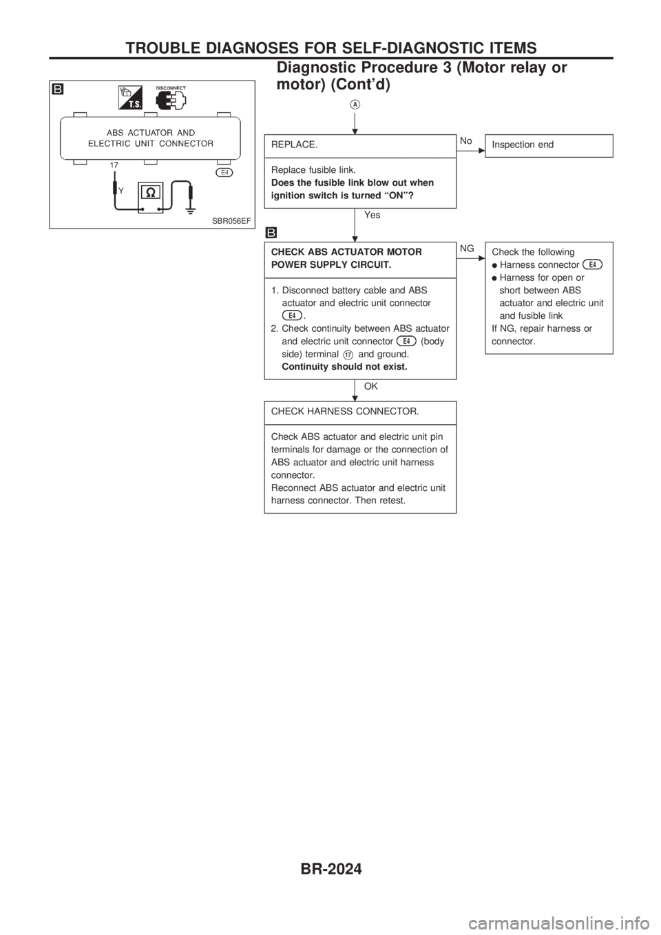
CHECK ABS ACTUATOR MOTOR
POWER SUPPLY CIRCUIT.
-------------------------------------------------------------------------------------------------------------------------------------------------------------------------------------------------------------------------------------------------------------------------------------------------------------
1. Disconnect battery cable and ABS
actuator and electric unit connector
E4.
2. Check continuity between ABS actuator
and electric unit connector
E4(body
side) terminal
V17and ground.
Continuity should not exist.
OK
cNG
Check the following
lHarness connectorE4
lHarness for open or
short between ABS
actuator and electric unit
and fusible link
If NG, repair harness or
connector.
CHECK HARNESS CONNECTOR.
-------------------------------------------------------------------------------------------------------------------------------------------------------------------------------------------------------------------------------------------------------------------------------------------------------------
Check ABS actuator and electric unit pin
terminals for damage or the connection of
ABS actuator and electric unit harness
connector.
Reconnect ABS actuator and electric unit
harness connector. Then retest.
SBR056EF
.
.
.
TROUBLE DIAGNOSES FOR SELF-DIAGNOSTIC ITEMS
Diagnostic Procedure 3 (Motor relay or
motor) (Cont'd)
BR-2024
Page 27 of 666

Diagnostic Procedure 4 (Low voltage)
Malfunction code No. 57
CHECK CONNECTOR.
-------------------------------------------------------------------------------------------------------------------------------------------------------------------------------------------------------------------------------------------------------------------------------------------------------------
1. Disconnect ABS actuator and electric
unit connector. Check terminals for
damage or loose connection. Then
reconnect connector.
2. Carry out self-diagnosis again.
Does warning lamp activate again?
Yes
cNo
Inspection end
CHECK ABS CONTROL UNIT POWER
SUPPLY CIRCUIT.
-------------------------------------------------------------------------------------------------------------------------------------------------------------------------------------------------------------------------------------------------------------------------------------------------------------
1. Disconnect ABS actuator and electric
unit connector.
2. Check voltage between ABS actuator
and electric unit connector
E4(body
side) terminal
V15and ground.
Battery voltage should exist when
ignition switch is turned ON.
OK
cNGVA(See below.)
CHECK ABS CONTROL UNIT GROUND.
-------------------------------------------------------------------------------------------------------------------------------------------------------------------------------------------------------------------------------------------------------------------------------------------------------------
Refer to ABS ACTUATOR AND ELEC-
TRIC UNIT GROUND in Ground Circuit
Check. Refer to original Service Manual.
OK
cNG
Repair harness and con-
nector.
CHECK HARNESS CONNECTOR.
-------------------------------------------------------------------------------------------------------------------------------------------------------------------------------------------------------------------------------------------------------------------------------------------------------------
Check ABS actuator and electric unit pin
terminals for damage or the connection of
ABS actuator and electric unit harness
connector. Reconnect ABS actuator and
electric unit harness connector. Then
retest.
VA
CHECK FUSE.
-------------------------------------------------------------------------------------------------------------------------------------------------------------------------------------------------------------------------------------------------------------------------------------------------------------
Check 10A fuse
18. For fuse layout, refer
to POWER SUPPLY ROUTING in EL
section.
OK
cNG
Replace fuse.
CHECK ABS CONTROL UNIT POWER
SUPPLY CIRCUIT.
-------------------------------------------------------------------------------------------------------------------------------------------------------------------------------------------------------------------------------------------------------------------------------------------------------------
Check continuity between battery and
ABS actuator and electric unit connector
E4(body side) terminalV15.
OK
cNG
Check the following.
lHarness connectorE4lHarness for open or
short between ABS
actuator and electric unit
and fuse
If NG, repair harness or
connector.
CHECK BATTERY.
-------------------------------------------------------------------------------------------------------------------------------------------------------------------------------------------------------------------------------------------------------------------------------------------------------------
Check battery. Refer to BATTERY in EL
section.
SBR057EA
SBR058EF
.
.
.
.
.
.
TROUBLE DIAGNOSES FOR SELF-DIAGNOSTIC ITEMS
BR-2025
Page 30 of 666

Diagnostic Procedure 12 (Warning lamp does
not come on when ignition switch is turned
ON.)
CHECK FUSE.
-------------------------------------------------------------------------------------------------------------------------------------------------------------------------------------------------------------------------------------------------------------------------------------------------------------
Check 10A fuse
20. For fuse layout, refer
to POWER SUPPLY ROUTING in EL
section.
OK
cNG
Replace fuse.
CHECK WARNING LAMP ACTIVATE.
-------------------------------------------------------------------------------------------------------------------------------------------------------------------------------------------------------------------------------------------------------------------------------------------------------------
Disconnect ABS actuator and electric unit
connector.
Does the warning lamp activate?
No
cYesVA(Go to next page.)
CHECK HARNESS FOR SHORT.
-------------------------------------------------------------------------------------------------------------------------------------------------------------------------------------------------------------------------------------------------------------------------------------------------------------
1. Disconnect ABS actuator and electric
unit connector.
2. Check voltage between ABS actuator
and electric unit connector
E4(body
side) terminal
V10(2WD) orV21(4WD)
and ground.
Battery voltage should not exist.
OK
cNG
Repair harness or connec-
tor.
CHECK COMBINATION METER.
-------------------------------------------------------------------------------------------------------------------------------------------------------------------------------------------------------------------------------------------------------------------------------------------------------------
Check combination meter. Refer to
WARNING LAMPS in EL section.
SBR063EA
SBR069E
SBR144E
.
.
.
TROUBLE DIAGNOSES FOR SYMPTOMS
BR-2028
Page 31 of 666

VA
CHECK HARNESS CONNECTOR.
-------------------------------------------------------------------------------------------------------------------------------------------------------------------------------------------------------------------------------------------------------------------------------------------------------------
Check ABS actuator and electric unit pin
terminals for damage or connection of
ABS actuator and electric unit harness
connector. Reconnect ABS actuator and
electric unit harness connector. Then
retest.
NG
cOK
Inspection end
REPLACE.
-------------------------------------------------------------------------------------------------------------------------------------------------------------------------------------------------------------------------------------------------------------------------------------------------------------
Replace ABS actuator and electric unit.
.
.
TROUBLE DIAGNOSES FOR SYMPTOMS
Diagnostic Procedure 12 (Warning lamp
does not come on when ignition switch is
turned ON.) (Cont'd)
BR-2029
Page 32 of 666

Diagnostic Procedure 13 (Warning lamp
stays on when ignition switch is turned ON.)
CHECK WARNING LAMP.
-------------------------------------------------------------------------------------------------------------------------------------------------------------------------------------------------------------------------------------------------------------------------------------------------------------
1. Disconnect ABS actuator and electric
unit connector.
2. Connect suitable wire between ABS
actuator and electric unit connector
E4(body side) terminalV10(2WD) or
V21(4WD) and ground.
Warning lamp should not activate.
OK
cNG
Repair combination meter.
Check the following.
lHarness connectorE4
lHarness for open or
short between ABS
actuator and electric unit
and fuse
If NG, repair harness or
connector.
CHECK HARNESS CONNECTOR.
-------------------------------------------------------------------------------------------------------------------------------------------------------------------------------------------------------------------------------------------------------------------------------------------------------------
Check ABS actuator and electric unit pin
terminals for damage or the connection of
ABS actuator and electric unit harness
connector. Reconnect ABS actuator and
electric unit harness connector. Then
retest.
NG
cOK
Inspection end
CHECK ABS MOTOR GROUND.
-------------------------------------------------------------------------------------------------------------------------------------------------------------------------------------------------------------------------------------------------------------------------------------------------------------
1. Turn ignition switch ªOFFº.
2. Disconnect ABS actuator and electric
unit connector.
3. Check continuity between ABS actuator
and electric unit connector
E4(body
side)
V16and ground.
Continuity should exist.
OK
cNG
Check the following.
lHarness connectorE4
lHarness for open or
short between ABS
actuator and electric unit
and ground
If NG, repair harness or
connector.
REPLACE.
-------------------------------------------------------------------------------------------------------------------------------------------------------------------------------------------------------------------------------------------------------------------------------------------------------------
Replace ABS actuator and electric unit.
SBR145EA
SBR146E
SBR147E
.
.
.
TROUBLE DIAGNOSES FOR SYMPTOMS
BR-2030
Page 81 of 666

WARNING LAMPS.............................................. 2072
Schematic ........................................................ 2072
Wiring Diagram - WARN -/Gasoline Engine.... 2073
Wiring Diagram - WARN -/Diesel Engine ........ 2078
Electrical Components Inspection ................... 2083
Wiring Diagram - CHIME -/LHD Models.......... 2084
Wiring Diagram - CHIME -/RHD Models ......... 2085
FRONT WIPER AND WASHER.......................... 2086
Wiring Diagram - WIPER -/LHD Models with
Intermittent ....................................................... 2086
Wiring Diagram - WIPER -/LHD Models
without Intermittent........................................... 2087
Wiring Diagram - WIPER -/RHD M/T Models
with Intermittent................................................ 2088
Wiring Diagram - WIPER -/RHD Models
without Intermittent........................................... 2090
HEADLAMP WASHER........................................ 2092
Wiring Diagram - HLC - ................................... 2092
HORN................................................................... 2093
Wiring Diagram - HORN -................................ 2093
CIGARETTE LIGHTER........................................ 2094
Wiring Diagram - CIGAR - ............................... 2094
CLOCK................................................................. 2095
Wiring Diagram - CLOCK - .............................. 2095
REAR WINDOW DEFOGGER AND MIRROR
DEFOGGER......................................................... 2096
Wiring Diagram - DEF -/LHD Models .............. 2096
Wiring Diagram - DEF -/RHD Models ............. 2097
Electrical Components Inspection ................... 2098
AUDIO.................................................................. 2099
Wiring Diagram - AUDIO -/LHD Models
Type-2 .............................................................. 2099
Wiring Diagram - AUDIO -/LHD Models
Type-3 .............................................................. 2100
Wiring Diagram - AUDIO -/RHD Models ......... 2102
AUDIO ANTENNA............................................... 2103
Power Antenna/Wiring Diagram - P/ANT - ...... 2103
POWER DOOR MIRROR.................................... 2104
Wiring Diagram - MIRROR -/LHD Models....... 2104
Wiring Diagram - MIRROR -/RHD Models ...... 2105
HEATED SEAT.................................................... 2106
Wiring Diagram - H/SEAT - ............................. 2106
POWER WINDOW............................................... 2108
Schematic/Without Interruption Detection
Function ........................................................... 2108Wiring Diagram - WINDOW -/Without
Interruption Detection Function........................ 2109
Trouble Diagnoses/Without Interruption
Detection Function ........................................... 2113
System Description/With Interruption Detection
Function ........................................................... 2114
Schematic/With Interruption Detection
Function ........................................................... 2115
Wiring Diagram - WINDOW -/With Interruption
Detection Function ........................................... 2116
Trouble Diagnoses/With Interruption Detection
Function ........................................................... 2120
POWER DOOR LOCK......................................... 2122
System Description .......................................... 2122
Wiring Diagram - D/LOCK - ............................. 2123
Trouble Diagnosis ............................................ 2125
MULTI-REMOTE CONTROL SYSTEM............... 2129
System Description .......................................... 2129
Schematic ........................................................ 2130
Wiring Diagram - MULTI - ............................... 2131
Trouble Diagnoses ........................................... 2135
ID Code Entry Procedure ................................ 2139
NATS (Nissan Anti-Theft System)/Models with
KA24E.................................................................. 2140
Wiring Diagram - NATS -................................. 2140
NATS (Nissan Anti-Theft System)/Diesel
engine.................................................................. 2141
Wiring Diagram - NATS -/LHD Models............ 2141
Wiring Diagram - NATS -/RHD Models ........... 2142
LOCATION OF ELECTRICAL UNITS................. 2143
Engine Compartment ....................................... 2143
Passenger Compartment ................................. 2144
HARNESS LAYOUT............................................ 2146
Main Harness ................................................... 2146
Engine Room Harness..................................... 2152
Engine Control Harness................................... 2160
Alternator Harness ........................................... 2164
Instrument Harness.......................................... 2165
Room Lamp Harness/LHD Models .................. 2166
Room Lamp Harness/RHD Models ................. 2167
Chassis Harness and Tail Harness ................. 2168
Front Door Harness (LH side) ......................... 2169
Front Door Harness (RH side)......................... 2170
WIRING DIAGRAM CODES (CELL CODES)..... 2171
WIRING DIAGRAM REFERENCE CHART
COOLING FAN .......................................................................................................... LC SECTION
ECCS, IGNITION SYSTEM, QUICK-GLOW SYSTEM, FUEL HEATER SYSTEM .. EC SECTION
ANTI-LOCK BRAKE SYSTEM .................................................................................. BR SECTION
SRS ``AIR BAG'' ........................................................................................................ RS SECTION
HEATER AND AIR CONDITIONER .......................................................................... HA SECTION
EL-2002