Page 84 of 666
Wiring Diagram Ð POWER Ð
BATTERY POWER SUPPLY Ð IGNITION SWITCH IN ANY POSITION
HEL670A
POWER SUPPLY ROUTING
EL-2005
Page 87 of 666
ACCESSORY POWER SUPPLY Ð IGNITION SW. IN ``ACC'' OR ``ON''
HEL673A
POWER SUPPLY ROUTING
Wiring Diagram Ð POWER Ð (Cont'd)
EL-2008
Page 88 of 666
IGNITION POWER SUPPLY Ð IGNITION SW. IN ``ON'' AND/OR ``START''
HEL674A
POWER SUPPLY ROUTING
Wiring Diagram Ð POWER Ð (Cont'd)
EL-2009
Page 137 of 666

Unified Control Meter System Description
UNIFIED CONTROL METER
Speedometer, odo/trip meter, tachometer, fuel gauge and water
temperature gauge are controlled totally by unified meter control
unit.
Meter/gauge Operation and Odo/Trip Meter
Segment Check in Diagnosis Mode
DIAGNOSIS FUNCTION
lOdo/trip meter segment can be checked in diagnosis mode.
lMeters/gauges can be checked in diagnosis mode.
HOW TO ALTERNATE DIAGNOSIS MODE
1. Turn ignition switch to ON and change odo/trip meter to
``TRIP A'' or ``TRIP B''.
2. Turn ignition switch to OFF.
3. Turn ignition switch to ON when pushing odo/trip meter
switch.
4. Confirm that trip meter indicates ``000.0''.
5. Push odo/trip meter switch more than three times within 5
seconds.
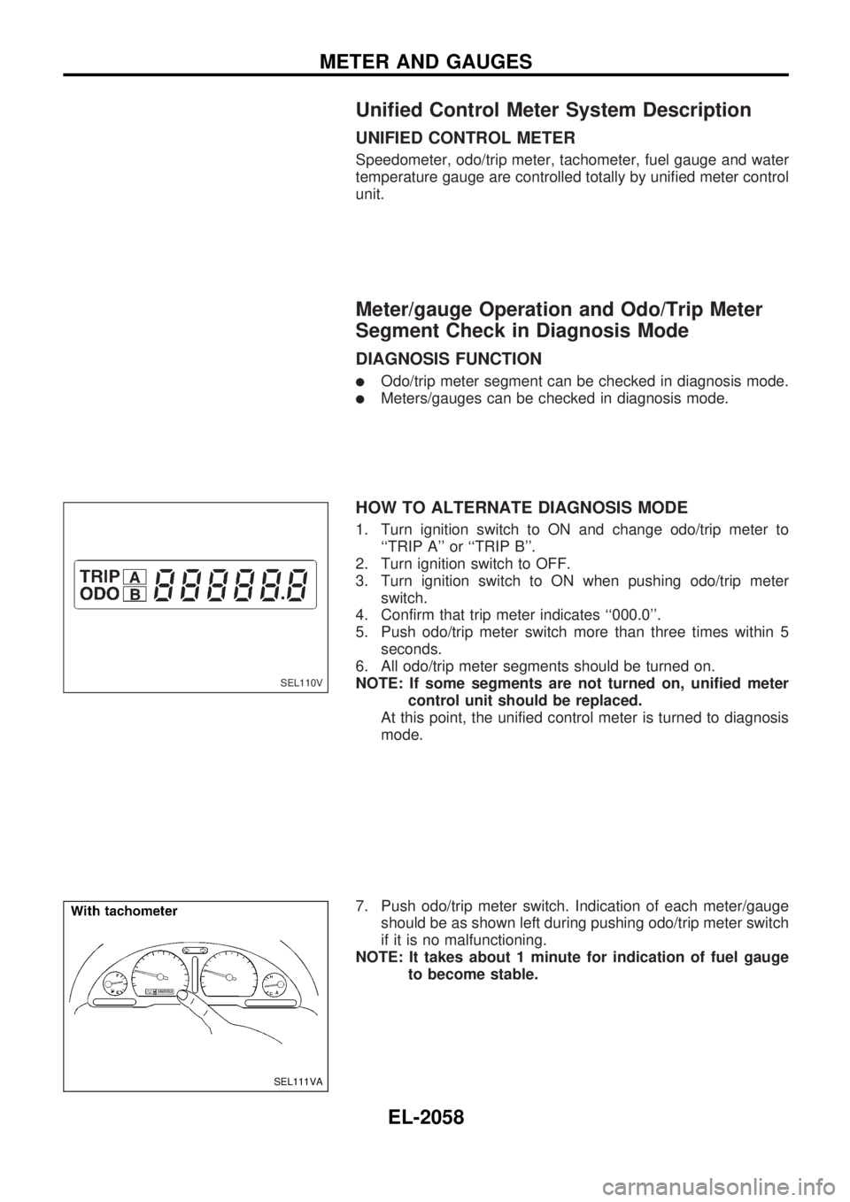
6. All odo/trip meter segments should be turned on.
NOTE: If some segments are not turned on, unified meter
control unit should be replaced.
At this point, the unified control meter is turned to diagnosis
mode.
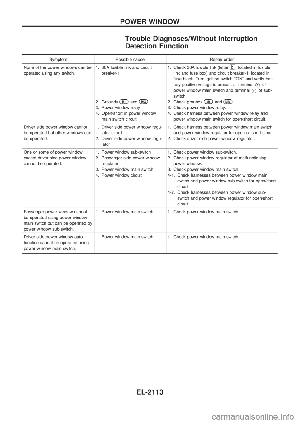
7. Push odo/trip meter switch. Indication of each meter/gauge
should be as shown left during pushing odo/trip meter switch
if it is no malfunctioning.
NOTE: It takes about 1 minute for indication of fuel gauge
to become stable.
SEL110V
SEL111VA
METER AND GAUGES
EL-2058
Page 141 of 666
POWER SUPPLY AND GROUND CIRCUIT CHECK
Power supply circuit check
Terminals Ignition switch position
Å@OFF ACC ON
V2GroundBattery
voltageBattery
voltageBattery
voltage
V37Ground 0V 0VBattery
voltage
If NG, check the following.
l7.5A fuse [No.3, located in fuse block (J/B)]
l10A fuse [No.20 , located in fuse block (J/B)]
lHarness for open or short between fuse and combination
meter
Ground circuit check
Terminals Continuity
V3- Ground Yes
SEL420W
SEL421W
METER AND GAUGES
Trouble Diagnoses/Models with Tachometer
(Cont'd)
EL-2062
Page 146 of 666
POWER SUPPLY AND GROUND CIRCUIT CHECK
Power supply circuit check
Terminals Ignition switch position
Å@OFF ACC ON
V21GroundBattery
voltageBattery
voltageBattery
voltage
V22Ground 0V 0VBattery
voltage
If NG, check the following.
l7.5A fuse [No.3, located in fuse block (J/B)]
l10A fuse [No.20, located in fuse block (J/B)]
lHarness for open or short between fuse and combination
meter
Ground circuit check
Terminals Continuity
V23- Ground Yes
SEL428W
SEL429W
METER AND GAUGES
Trouble Diagnoses/Models without
Tachometer (Cont'd)
EL-2067
Page 192 of 666

Trouble Diagnoses/Without Interruption
Detection Function
Symptom Possible cause Repair order
None of the power windows can be
operated using any switch.1. 30A fusible link and circuit
breaker-1
2. Grounds
M1andM54
3. Power window relay
4. Open/short in power window
main switch circuit1. Check 30A fusible link (letter
b, located in fusible
link and fuse box) and circuit breaker-1, located in
fuse block. Turn ignition switch ``ON'' and verify bat-
tery positive voltage is present at terminal
V1of
power window main switch and terminal
V5of sub-
switch.
2. Check grounds
M1andM54.
3. Check power window relay.
4. Check harness between power window relay and
power window main switch for open/short circuit.
Driver side power window cannot
be operated but other windows can
be operated.1. Driver side power window regu-
lator circuit
2. Driver side power window regu-
lator1. Check harness between power window main switch
and power window regulator for open or short circuit.
2. Check driver side power window regulator.
One or some of power window
except driver side power window
cannot be operated.1. Power window sub-switch
2. Passenger side power window
regulator
3. Power window main switch
4. Power window circuit1. Check power window sub-switch.
2. Check power window regulator of malfunctioning
power window.
3. Check power window main switch.
4-1. Check harnesses between power window main
switch and power window sub-switch for open/short
circuit.
4-2. Check harnesses between power window sub-
switch and power window regulator for open/short
circuit.
Passenger power window cannot
be operated using power window
main switch but can be operated by
power window sub-switch.1. Power window main switch 1. Check power window main switch.
Driver side power window auto
function cannot be operated using
power window main switch.1. Power window main switch 1. Check power window main switch.
POWER WINDOW
EL-2113
Page 193 of 666

System Description/With Interruption
Detection Function
OUTLINE
Power window system consists of
lCPU (combined with power window main switch)
lfour power window regulators
When ignition switch is in the ``ON'' position, power window can be operated depending on power window
sub/main switch condition.
OPERATIVE CONDITION
lPower windows can be raised or lowered with each sub-switch or the power window main switch located
on the driver's door trim when ignition switch is in the ``ON'' position and power window lock switch on
the driver's door trim is unlocked.
lWhen power window lock switch is locked, no windows can be raised or lowered except for driver's side
window.
lWhen ignition switch is in the ``ON'' position, to fully open/close the driver's side window, press down/
pull up completely on the automatic switch (main switch) and release it; it needs not be held. The win-
dow will automatically open/close all the way. To stop the window, pull up/press down then release the
switch.
lAfter turning ignition switch to OFF, the driver's side window can be raised or lowered for 15 minutes.
The timer control for supplying power after turning ignition switch to ``OFF'' will be canceled when the
driver's side door is closed. (Except models for Europe)
INTERRUPTION DETECTION FUNCTION
CPU (combined with power window main switch) monitors the power window regulator motor operation and
the power window position (full closed or other) for driver's power window by the signals from encoder and
limit switch in front power window regulator (driver's side).
When CPU (combined with power window main switch) detects interruption during the following close
operation in the driver's side door,
lautomatic close operation when ignition switch is in the ``ON'' position
lautomatic close operation during power window timer operation
lmanual close operation during power window timer operation
CPU (combined with power window main switch) controls driver's power window regulator motor for open
and the power window will be lowered about 150 mm (5.91 in).
POWER WINDOW
EL-2114