1999 NISSAN PICK-UP remote control
[x] Cancel search: remote controlPage 81 of 666
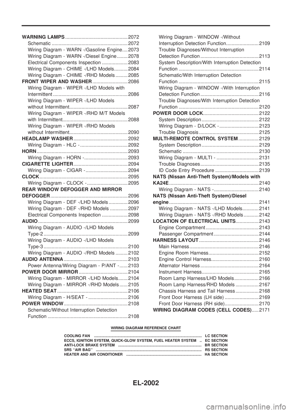
WARNING LAMPS.............................................. 2072
Schematic ........................................................ 2072
Wiring Diagram - WARN -/Gasoline Engine.... 2073
Wiring Diagram - WARN -/Diesel Engine ........ 2078
Electrical Components Inspection ................... 2083
Wiring Diagram - CHIME -/LHD Models.......... 2084
Wiring Diagram - CHIME -/RHD Models ......... 2085
FRONT WIPER AND WASHER.......................... 2086
Wiring Diagram - WIPER -/LHD Models with
Intermittent ....................................................... 2086
Wiring Diagram - WIPER -/LHD Models
without Intermittent........................................... 2087
Wiring Diagram - WIPER -/RHD M/T Models
with Intermittent................................................ 2088
Wiring Diagram - WIPER -/RHD Models
without Intermittent........................................... 2090
HEADLAMP WASHER........................................ 2092
Wiring Diagram - HLC - ................................... 2092
HORN................................................................... 2093
Wiring Diagram - HORN -................................ 2093
CIGARETTE LIGHTER........................................ 2094
Wiring Diagram - CIGAR - ............................... 2094
CLOCK................................................................. 2095
Wiring Diagram - CLOCK - .............................. 2095
REAR WINDOW DEFOGGER AND MIRROR
DEFOGGER......................................................... 2096
Wiring Diagram - DEF -/LHD Models .............. 2096
Wiring Diagram - DEF -/RHD Models ............. 2097
Electrical Components Inspection ................... 2098
AUDIO.................................................................. 2099
Wiring Diagram - AUDIO -/LHD Models
Type-2 .............................................................. 2099
Wiring Diagram - AUDIO -/LHD Models
Type-3 .............................................................. 2100
Wiring Diagram - AUDIO -/RHD Models ......... 2102
AUDIO ANTENNA............................................... 2103
Power Antenna/Wiring Diagram - P/ANT - ...... 2103
POWER DOOR MIRROR.................................... 2104
Wiring Diagram - MIRROR -/LHD Models....... 2104
Wiring Diagram - MIRROR -/RHD Models ...... 2105
HEATED SEAT.................................................... 2106
Wiring Diagram - H/SEAT - ............................. 2106
POWER WINDOW............................................... 2108
Schematic/Without Interruption Detection
Function ........................................................... 2108Wiring Diagram - WINDOW -/Without
Interruption Detection Function........................ 2109
Trouble Diagnoses/Without Interruption
Detection Function ........................................... 2113
System Description/With Interruption Detection
Function ........................................................... 2114
Schematic/With Interruption Detection
Function ........................................................... 2115
Wiring Diagram - WINDOW -/With Interruption
Detection Function ........................................... 2116
Trouble Diagnoses/With Interruption Detection
Function ........................................................... 2120
POWER DOOR LOCK......................................... 2122
System Description .......................................... 2122
Wiring Diagram - D/LOCK - ............................. 2123
Trouble Diagnosis ............................................ 2125
MULTI-REMOTE CONTROL SYSTEM............... 2129
System Description .......................................... 2129
Schematic ........................................................ 2130
Wiring Diagram - MULTI - ............................... 2131
Trouble Diagnoses ........................................... 2135
ID Code Entry Procedure ................................ 2139
NATS (Nissan Anti-Theft System)/Models with
KA24E.................................................................. 2140
Wiring Diagram - NATS -................................. 2140
NATS (Nissan Anti-Theft System)/Diesel
engine.................................................................. 2141
Wiring Diagram - NATS -/LHD Models............ 2141
Wiring Diagram - NATS -/RHD Models ........... 2142
LOCATION OF ELECTRICAL UNITS................. 2143
Engine Compartment ....................................... 2143
Passenger Compartment ................................. 2144
HARNESS LAYOUT............................................ 2146
Main Harness ................................................... 2146
Engine Room Harness..................................... 2152
Engine Control Harness................................... 2160
Alternator Harness ........................................... 2164
Instrument Harness.......................................... 2165
Room Lamp Harness/LHD Models .................. 2166
Room Lamp Harness/RHD Models ................. 2167
Chassis Harness and Tail Harness ................. 2168
Front Door Harness (LH side) ......................... 2169
Front Door Harness (RH side)......................... 2170
WIRING DIAGRAM CODES (CELL CODES)..... 2171
WIRING DIAGRAM REFERENCE CHART
COOLING FAN .......................................................................................................... LC SECTION
ECCS, IGNITION SYSTEM, QUICK-GLOW SYSTEM, FUEL HEATER SYSTEM .. EC SECTION
ANTI-LOCK BRAKE SYSTEM .................................................................................. BR SECTION
SRS ``AIR BAG'' ........................................................................................................ RS SECTION
HEATER AND AIR CONDITIONER .......................................................................... HA SECTION
EL-2002
Page 208 of 666
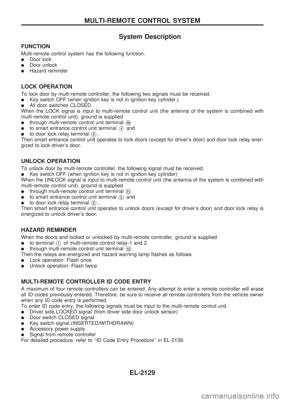
System Description
FUNCTION
Multi-remote control system has the following function.
lDoor lock
lDoor unlock
lHazard reminder
LOCK OPERATION
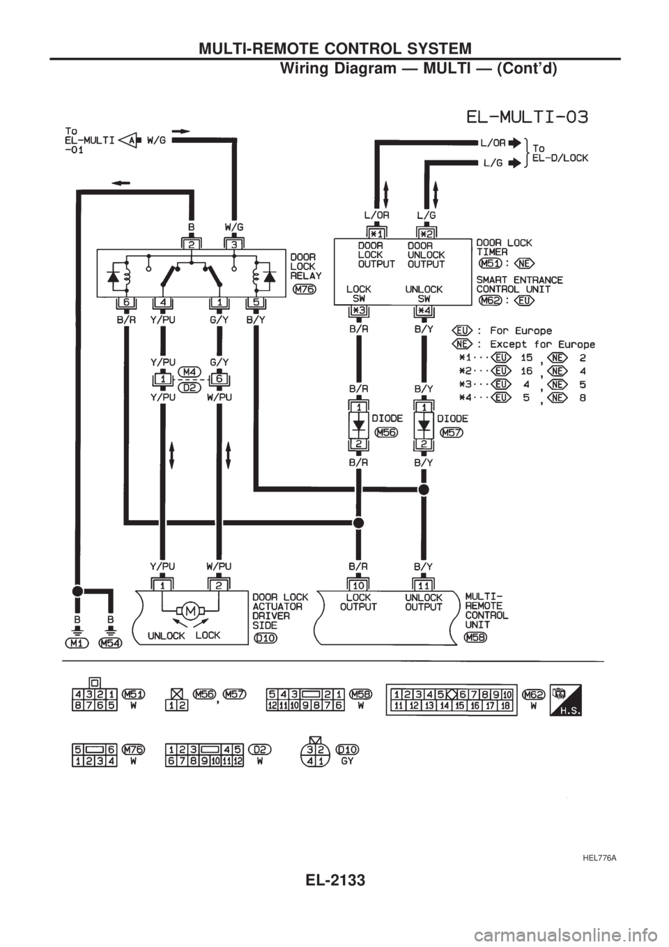
To lock door by multi-remote controller, the following two signals must be received.
lKey switch OFF (when ignition key is not in ignition key cylinder.)
lAll door switches CLOSED
When the LOCK signal is input to multi-remote control unit (the antenna of the system is combined with
multi-remote control unit), ground is supplied
lthrough multi-remote control unit terminalV10
lto smart entrance control unit terminalV4and
lto door lock relay terminalV6.
Then smart entrance control unit operates to lock doors (except for driver's door) and door lock relay ener-
gized to lock driver's door.
UNLOCK OPERATION
To unlock door by multi-remote controller, the following signal must be received.
lKey switch OFF (when ignition key is not in ignition key cylinder)
When the UNLOCK signal is input to multi-remote control unit (the antenna of the system is combined with
multi-remote control unit), ground is supplied
lthrough multi-remote control unit terminalV11
lto smart entrance control unit terminalV5and
lto door lock relay terminalV5.
Then smart entrance control unit operates to unlock doors (except for driver's door) and door lock relay is
energized to unlock driver's door.
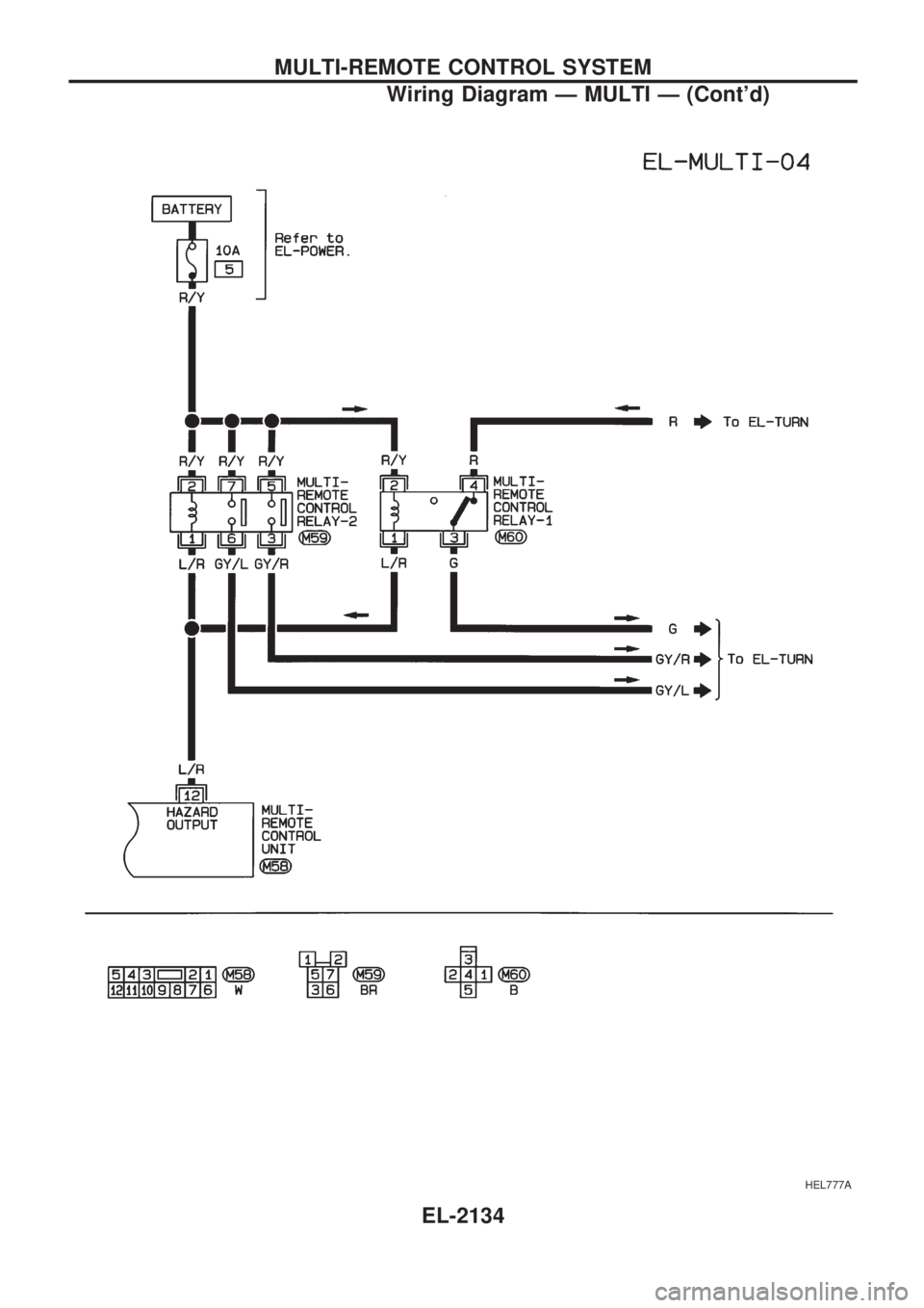
HAZARD REMINDER
When the doors and locked or unlocked by multi-remote controller, ground is supplied
lto terminalV1of multi-remote control relay-1 and 2
lthrough multi-remote control unit terminalV12.
Then the relays are energized and hazard warning lamp flashes as follows
lLock operation: Flash once
lUnlock operation: Flash twice
MULTI-REMOTE CONTROLLER ID CODE ENTRY
A maximum of four remote controllers can be entered. Any attempt to enter a remote controller will erase
all ID codes previously entered. Therefore, be sure to receive all remote controllers from the vehicle owner
when any ID code entry is performed.
To enter ID code entry, the following signals must be input to the multi-remote control unit.
lDriver side LOCKED signal (from driver side door unlock sensor)
lDoor switch CLOSED signal
lKey switch signal (INSERTED/WITHDRAWN)
lAccessory power supply
lSignal from remote controller
For detailed procedure, refer to ``ID Code Entry Procedure'' in EL-2139.
MULTI-REMOTE CONTROL SYSTEM
EL-2129
Page 209 of 666
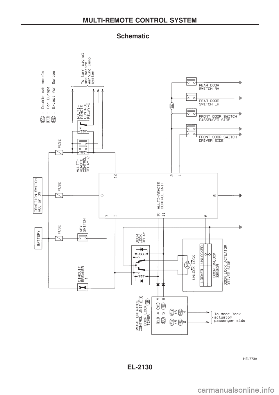
Schematic
HEL773A
MULTI-REMOTE CONTROL SYSTEM
EL-2130
Page 210 of 666
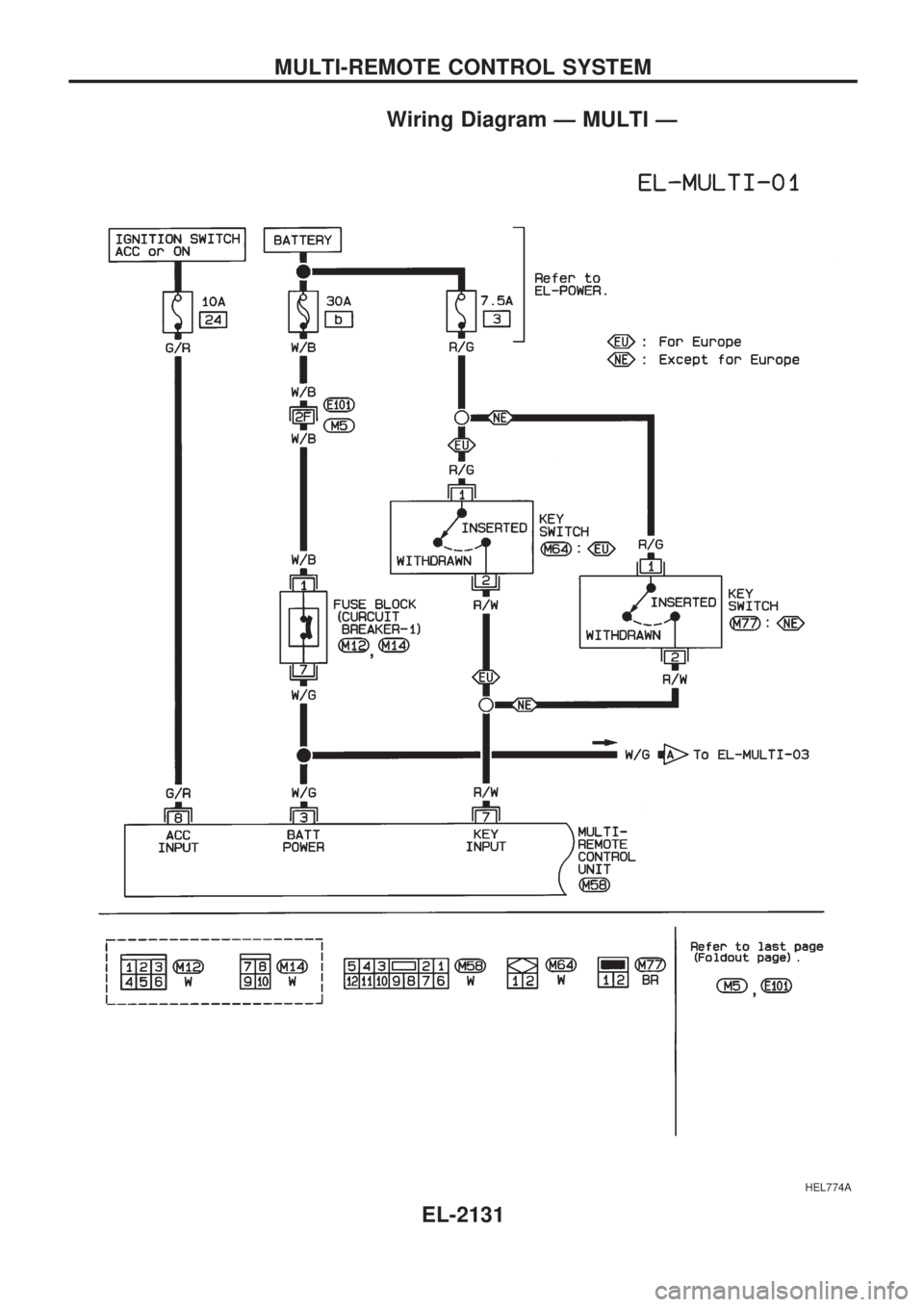
Wiring Diagram Ð MULTI Ð
HEL774A
MULTI-REMOTE CONTROL SYSTEM
EL-2131
Page 211 of 666
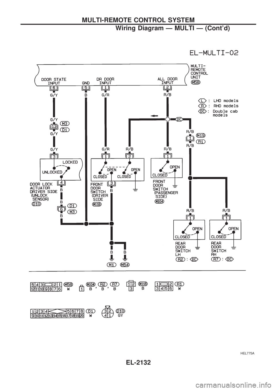
HEL775A
MULTI-REMOTE CONTROL SYSTEM
Wiring Diagram Ð MULTI Ð (Cont'd)
EL-2132
Page 212 of 666
HEL776A
MULTI-REMOTE CONTROL SYSTEM
Wiring Diagram Ð MULTI Ð (Cont'd)
EL-2133
Page 213 of 666
HEL777A
MULTI-REMOTE CONTROL SYSTEM
Wiring Diagram Ð MULTI Ð (Cont'd)
EL-2134
Page 214 of 666
Trouble Diagnoses
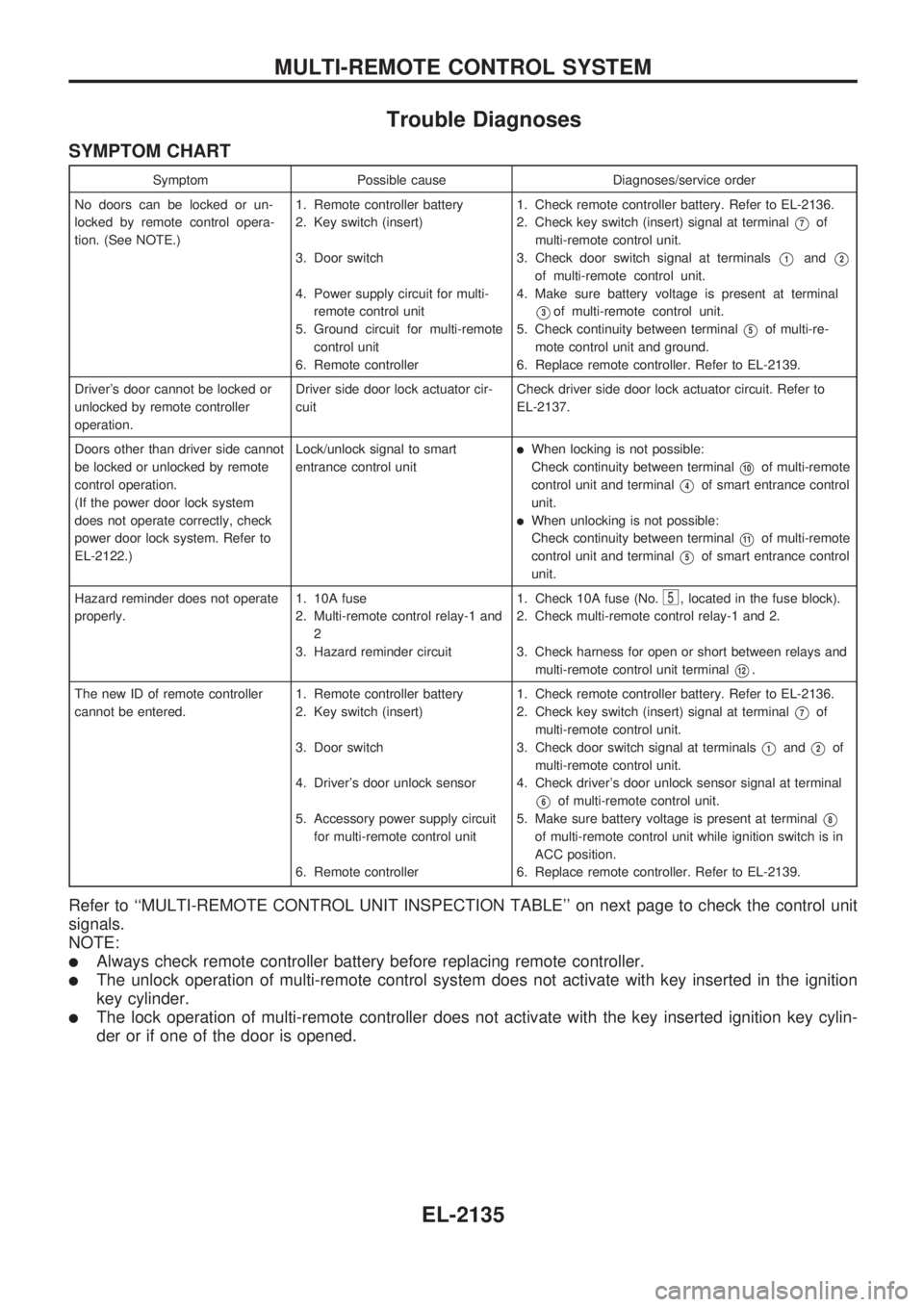
SYMPTOM CHART
Symptom Possible cause Diagnoses/service order
No doors can be locked or un-
locked by remote control opera-
tion. (See NOTE.)1. Remote controller battery
2. Key switch (insert)
3. Door switch
4. Power supply circuit for multi-
remote control unit
5. Ground circuit for multi-remote
control unit
6. Remote controller1. Check remote controller battery. Refer to EL-2136.
2. Check key switch (insert) signal at terminal
V7of
multi-remote control unit.
3. Check door switch signal at terminals
V1andV2
of multi-remote control unit.
4. Make sure battery voltage is present at terminal
V3of multi-remote control unit.
5. Check continuity between terminal
V5of multi-re-
mote control unit and ground.
6. Replace remote controller. Refer to EL-2139.
Driver's door cannot be locked or
unlocked by remote controller
operation.Driver side door lock actuator cir-
cuitCheck driver side door lock actuator circuit. Refer to
EL-2137.
Doors other than driver side cannot
be locked or unlocked by remote
control operation.
(If the power door lock system
does not operate correctly, check
power door lock system. Refer to
EL-2122.)Lock/unlock signal to smart
entrance control unit
lWhen locking is not possible:
Check continuity between terminal
V10of multi-remote
control unit and terminal
V4of smart entrance control
unit.
lWhen unlocking is not possible:
Check continuity between terminal
V11of multi-remote
control unit and terminal
V5of smart entrance control
unit.
Hazard reminder does not operate
properly.1. 10A fuse
2. Multi-remote control relay-1 and
2
3. Hazard reminder circuit1. Check 10A fuse (No.
5, located in the fuse block).
2. Check multi-remote control relay-1 and 2.
3. Check harness for open or short between relays and
multi-remote control unit terminal
V12.
The new ID of remote controller
cannot be entered.1. Remote controller battery
2. Key switch (insert)
3. Door switch
4. Driver's door unlock sensor
5. Accessory power supply circuit
for multi-remote control unit
6. Remote controller1. Check remote controller battery. Refer to EL-2136.
2. Check key switch (insert) signal at terminal
V7of
multi-remote control unit.
3. Check door switch signal at terminals
V1andV2of
multi-remote control unit.
4. Check driver's door unlock sensor signal at terminal
V6of multi-remote control unit.
5. Make sure battery voltage is present at terminal
V8
of multi-remote control unit while ignition switch is in
ACC position.
6. Replace remote controller. Refer to EL-2139.
Refer to ``MULTI-REMOTE CONTROL UNIT INSPECTION TABLE'' on next page to check the control unit
signals.
NOTE:
lAlways check remote controller battery before replacing remote controller.
lThe unlock operation of multi-remote control system does not activate with key inserted in the ignition
key cylinder.
lThe lock operation of multi-remote controller does not activate with the key inserted ignition key cylin-
der or if one of the door is opened.
MULTI-REMOTE CONTROL SYSTEM
EL-2135