1999 NISSAN PICK-UP AUX
[x] Cancel search: AUXPage 46 of 666
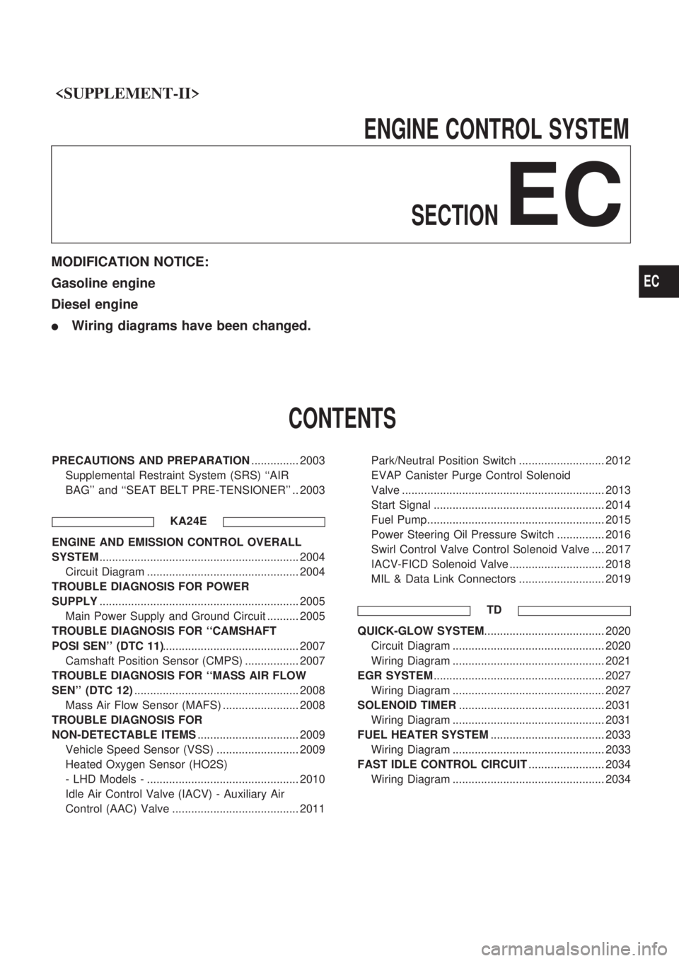
ENGINECONTROLSYSTEM
SECTION
EC
MODIFICATION NOTICE:
Gasoline engine
Diesel engine
lWiring diagrams have been changed.
CONTENTS
PRECAUTIONS AND PREPARATION ............... 2003
Supplemental Restraint System (SRS) ``AIR
BAG'' and ``SEAT BELT PRE-TENSIONER'' .. 2003
KA24E
ENGINE AND EMISSION CONTROL OVERALL
SYSTEM............................................................... 2004
Circuit Diagram ................................................ 2004
TROUBLE DIAGNOSIS FOR POWER
SUPPLY ............................................................... 2005
Main Power Supply and Ground Circuit .......... 2005
TROUBLE DIAGNOSIS FOR ``CAMSHAFT
POSI SEN'' (DTC 11) ........................................... 2007
Camshaft Position Sensor (CMPS) ................. 2007
TROUBLE DIAGNOSIS FOR ``MASS AIR FLOW
SEN'' (DTC 12) .................................................... 2008
Mass Air Flow Sensor (MAFS) ........................ 2008
TROUBLE DIAGNOSIS FOR
NON-DETECTABLE ITEMS ................................ 2009
Vehicle Speed Sensor (VSS) .......................... 2009
Heated Oxygen Sensor (HO2S)
- LHD Models - ................................................ 2010
Idle Air Control Valve (IACV) - Auxiliary Air
Control (AAC) Valve ........................................ 2011 Park/Neutral Position Switch ........................... 2012
EVAP Canister Purge Control Solenoid
Valve ................................................................ 2013
Start Signal ...................................................... 2014
Fuel Pump........................................................ 2015
Power Steering Oil Pressure Switch ............... 2016
Swirl Control Valve Control Solenoid Valve .... 2017
IACV-FICD Solenoid Valve .............................. 2018
MIL & Data Link Connectors ........................... 2019
TD
QUICK-GLOW SYSTEM ...................................... 2020
Circuit Diagram ................................................ 2020
Wiring Diagram ................................................ 2021
EGR SYSTEM ...................................................... 2027
Wiring Diagram ................................................ 2027
SOLENOID TIMER .............................................. 2031
Wiring Diagram ................................................ 2031
FUEL HEATER SYSTEM .................................... 2033
Wiring Diagram ................................................ 2033
FAST IDLE CONTROL CIRCUIT ........................ 2034
Wiring Diagram ................................................ 2034
EC
Page 56 of 666
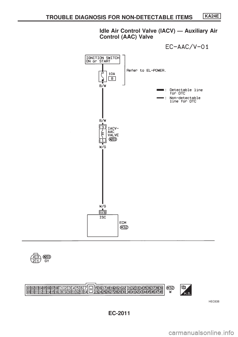
Idle Air Control Valve (IACV) Ð Auxiliary Air
Control (AAC) Valve
HEC638
TROUBLE DIAGNOSIS FOR NON-DETECTABLE ITEMSKA24E
EC-2011
Page 534 of 666
Self-diagnosis
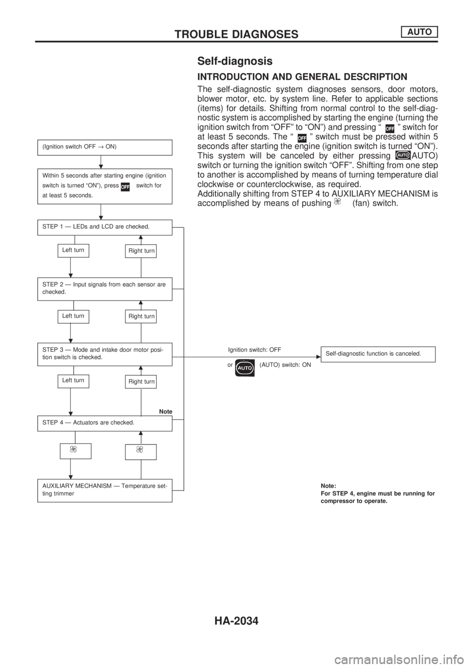
INTRODUCTION AND GENERAL DESCRIPTION
The self-diagnostic system diagnoses sensors, door motors,
blower motor, etc. by system line. Refer to applicable sections
(items) for details. Shifting from normal control to the self-diag-
nostic system is accomplished by starting the engine (turning the
ignition switch from ªOFFº to ªONº) and pressing ª
º switch for
at least 5 seconds. The ª
º switch must be pressed within 5
seconds after starting the engine (ignition switch is turned ªONº).
This system will be canceled by either pressing
(AUTO)
switch or turning the ignition switch ªOFFº. Shifting from one step
to another is accomplished by means of turning temperature dial
clockwise or counterclockwise, as required.
Additionally shifting from STEP 4 to AUXILIARY MECHANISM is
accomplished by means of pushing
(fan) switch.
(Ignition switch OFF®ON)
Within 5 seconds after starting engine (ignition
switch is turned ªONº), press
switch for
at least 5 seconds.
STEP 1 Ð LEDs and LCD are checked.
m
Left turnRight turn
STEP 2 Ð Input signals from each sensor are
checked.
m
Left turnRight turn
STEP 3 Ð Mode and intake door motor posi-
tion switch is checked.Ignition switch: OFFc
or(AUTO) switch: ONSelf-diagnostic function is canceled.m
Left turnRight turn
Note
STEP 4 Ð Actuators are checked.
m
AUXILIARY MECHANISM Ð Temperature set-
ting trimmerNote:
For STEP 4, engine must be running for
compressor to operate.
.
.
.
.
.
.
TROUBLE DIAGNOSESAUTO
HA-2034
Page 539 of 666
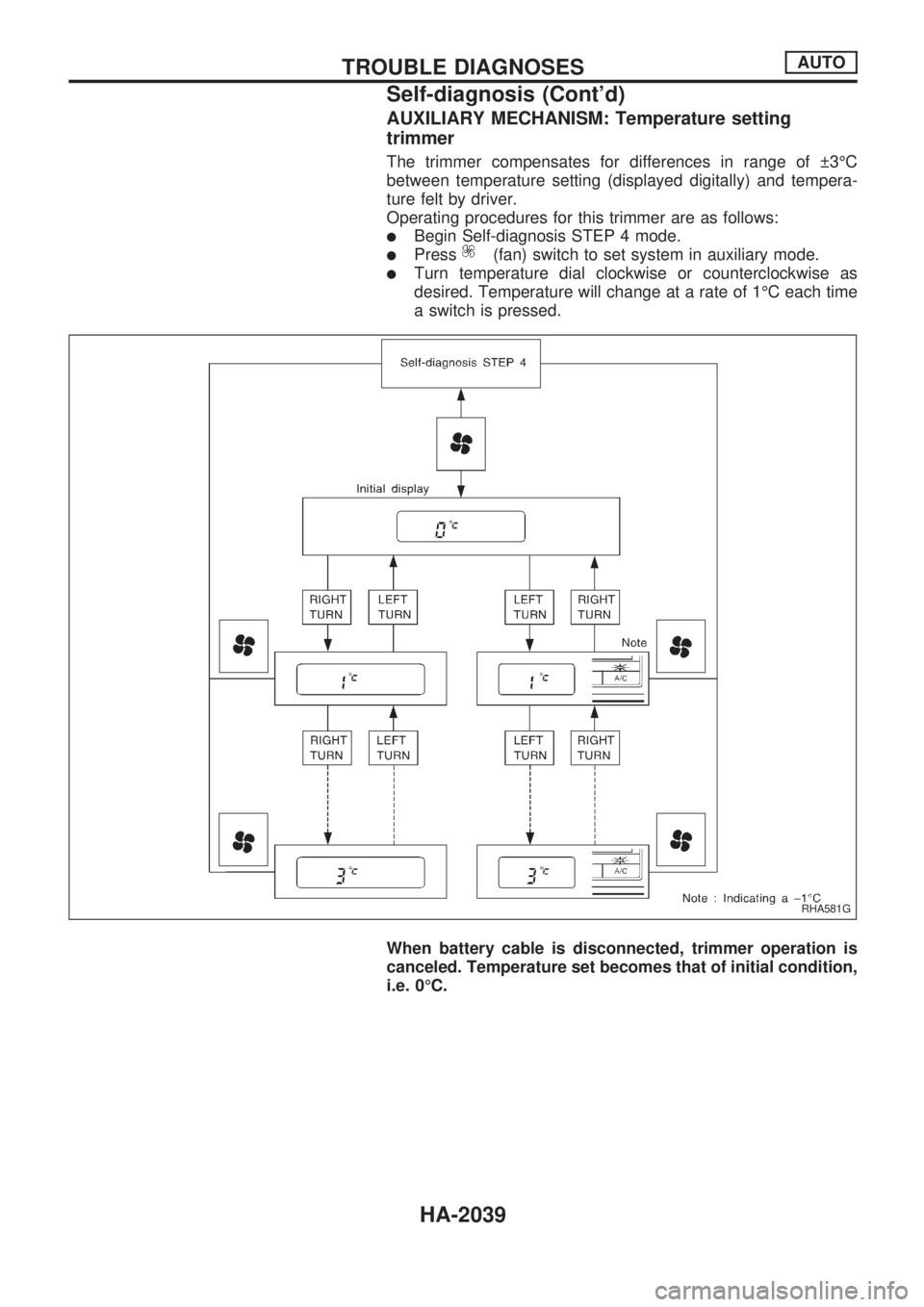
AUXILIARY MECHANISM: Temperature setting
trimmer
The trimmer compensates for differences in range of 3ÉC
between temperature setting (displayed digitally) and tempera-
ture felt by driver.
Operating procedures for this trimmer are as follows:
lBegin Self-diagnosis STEP 4 mode.
lPress(fan) switch to set system in auxiliary mode.
lTurn temperature dial clockwise or counterclockwise as
desired. Temperature will change at a rate of 1ÉC each time
a switch is pressed.
When battery cable is disconnected, trimmer operation is
canceled. Temperature set becomes that of initial condition,
i.e. 0ÉC.
RHA581G
TROUBLE DIAGNOSESAUTO
Self-diagnosis (Cont'd)
HA-2039
Page 590 of 666
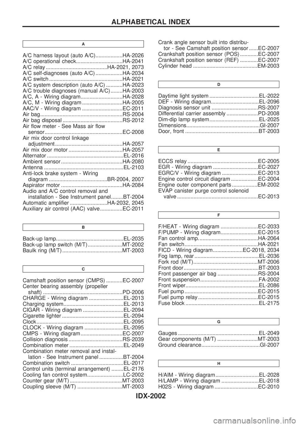
A
A/C harness layout (auto A/C)..................HA-2026
A/C operational check...............................HA-2041
A/C relay .........................................HA-2021, 2073
A/C self-diagnoses (auto A/C) ..................HA-2034
A/C switch .................................................HA-2021
A/C system description (auto A/C) ...........HA-2023
A/C trouble diagnoses (manual A/C) ........HA-2003
A/C, A - Wiring diagram............................HA-2028
A/C, M - Wiring diagram ...........................HA-2005
AAC/V - Wiring diagram ...........................EC-2011
Air bag.......................................................RS-2004
Air bag disposal ........................................RS-2012
Air flow meter - See Mass air flow
sensor....................................................EC-2008
Air mix door control linkage
adjustment .............................................HA-2057
Air mix door motor ....................................HA-2057
Alternator ...................................................EL-2016
Ambient sensor .........................................HA-2080
Antenna .....................................................EL-2103
Anti-lock brake system - Wiring
diagram .......................................BR-2004, 2007
Aspirator motor .........................................HA-2084
Audio and A/C control removal and
installation - See Instrument panel........BT-2004
Automatic amplifier .........................HA-2032, 2045
Auxiliary air control (AAC) valve ...............EC-2011
B
Back-up lamp.............................................EL-2035
Back-up lamp switch (M/T) .......................MT-2002
Baulk ring (M/T) ........................................MT-2003
C
Camshaft position sensor (CMPS) ...........EC-2007
Center bearing assembly (propeller
shaft) .....................................................PD-2006
CHARGE - Wiring diagram .......................EL-2013
Charging system........................................EL-2013
CIGAR - Wiring diagram ...........................EL-2094
Cigarette lighter .........................................EL-2094
Clock ..........................................................EL-2095
CLOCK - Wiring diagram ..........................EL-2095
CMPS - Wiring diagram ............................EC-2007
Collision diagnosis ....................................RS-2039
Combination meter ....................................EL-2049
Combination meter removal and instal-
lation - See Instrument panel ................BT-2004
Combination switch ...................................EL-2017
Control units (terminal arrangement) ........EL-2176
Cooling fan control system........................LC-2002
Counter gear (M/T) ...................................MT-2003
Coupling sleeve (M/T) ..............................MT-2003Crank angle sensor built into distribu-
tor - See Camshaft position sensor ......EC-2007
Crankshaft position sensor (POS) ............EC-2007
Crankshaft position sensor (REF) ............EC-2007
Cylinder head ...........................................EM-2003
D
Daytime light system .................................EL-2022
DEF - Wiring diagram................................EL-2096
Diagnosis sensor unit ...............................RS-2007
Differential carrier assembly .....................PD-2008
Dim-dip lamp system .................................EL-2025
Dimensions.................................................GI-2007
Door, front .................................................BT-2003
E
ECCS relay ...............................................EC-2005
EGR - Wiring diagram ..............................EC-2027
EGRC/V - Wiring diagram ........................EC-2013
Engine control circuit diagram ..................EC-2004
Engine outer component parts .................EM-2002
EVAP canister purge control solenoid
valve ......................................................EC-2013
F
F/HEAT - Wiring diagram .........................EC-2033
F/PUMP - Wiring diagram.........................EC-2015
Fan control amp. .......................................HA-2064
Fan switch .................................................HA-2021
FICD - Wiring diagram....................EC-2018, 2034
Fog lamp, rear ...........................................EL-2036
Fork rod (M/T)...........................................MT-2006
Front door ..................................................BT-2003
Front passenger air bag ...........................RS-2004
Front suspension .......................................FA-2002
Front wiper.................................................EL-2086
Fuel pump .................................................EC-2015
Fuel pump relay ........................................EC-2015
Fuse block .................................................EL-2175
G
Gauges ......................................................EL-2049
Gear components (M/T) ...........................MT-2003
Ground clearance.......................................GI-2007
H
H/AIM - Wiring diagram .............................EL-2028
H/LAMP - Wiring diagram .........................EL-2018
H02S - Wiring diagram .............................EC-2010
ALPHABETICAL INDEX
IDX-2002