1999 NISSAN PICK-UP IGNITION
[x] Cancel search: IGNITIONPage 422 of 666
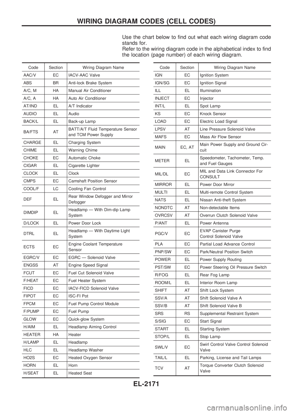
Use the chart below to find out what each wiring diagram code
stands for.
Refer to the wiring diagram code in the alphabetical index to find
the location (page number) of each wiring diagram.
Code Section Wiring Diagram Name
AAC/V EC IACV-AAC Valve
ABS BR Anti-lock Brake System
A/C, M HA Manual Air Conditioner
A/C, A HA Auto Air Conditioner
AT/IND EL A/T Indicator
AUDIO EL Audio
BACK/L EL Back-up Lamp
BA/FTS ATBATT/A/T Fluid Temperature Sensor
and TCM Power Supply
CHARGE EL Charging System
CHIME EL Warning Chime
CHOKE EC Automatic Choke
CIGAR EL Cigarette Lighter
CLOCK EL Clock
CMPS EC Camshaft Position Sensor
COOL/F LC Cooling Fan Control
DEF ELRear Window Defogger and Mirror
Defogger
DIMDIP ELHeadlamp Ð With Dim-dip Lamp
System
D/LOCK EL Power Door Lock
DTRL ELHeadlamp Ð With Daytime Light
System
ECTS ECEngine Coolant Temperature
Sensor
EGRC/V EC EGRC Ð Solenoid Valve
ENGSS AT Engine Speed Signal
FCUT EC Fuel Cut Solenoid Valve
F/HEAT EC Fuel Heater System
FICD EC IACV-FICD Solenoid Valve
FIPOT EC ISC-FI Pot
FPCM EC Fuel Pump Control Module
F/PUMP EC Fuel Pump
GLOW EC Quick-glow System
H/AIM EL Headlamp Aiming Control
HEATER HA Heater
H/LAMP EL Headlamp
HLC EL Headlamp Washer
HO2S EC Heated Oxygen Sensor
HORN EL Horn
H/SEAT EL Heated SeatCode Section Wiring Diagram Name
IGN EC Ignition System
IGN/SG EC Ignition Signal
ILL EL Illumination
INJECT EC Injector
INT/L EL Spot Lamp
KS EC Knock Sensor
LOAD EC Electric Load Signal
LPSV AT Line Pressure Solenoid Valve
MAFS EC Mass Air Flow Sensor
MAIN EC, ATMain Power Supply and Ground Cir-
cuit
METER ELSpeedometer, Tachometer, Temp.
and Fuel Gauges
MIL/DL ECMIL and Data Link Connector For
CONSULT
MIRROR EL Power Door Mirror
MULTI EL Multi-remote Control System
NATS EL Nissan Anti-theft System
NONDTC AT Non-detectable Items
OVRCSV AT Overrun Clutch Solenoid Valve
P/ANT EL Power Antenna
PGC/V ECEVAP Canister Purge
Control Solenoid Valve
PLA EC Partial Load Advance Control
PNP/SW EC Park/Neutral Position Switch
POWER EL Power Supply Routing
PST/SW EC Power Steering Oil Pressure Switch
R/FOG EL Rear Fog Lamp
ROOM/L EL Interior Room Lamp
SHIFT AT Shift Lock System
SSV/A AT Shift Solenoid Valve A
SSV/B AT Shift Solenoid Valve B
SRS RS Supplemental Restraint System
S/SIG EC Start Signal
START EL Starting System
STOP/L EL Stop Lamp
SWL/V ECSwirl Control Valve Control Solenoid
Valve
TAIL/L EL Parking, License and Tail Lamps
TCV ATTorque Converter Clutch Solenoid
Valve
WIRING DIAGRAM CODES (CELL CODES)
EL-2171
Page 436 of 666
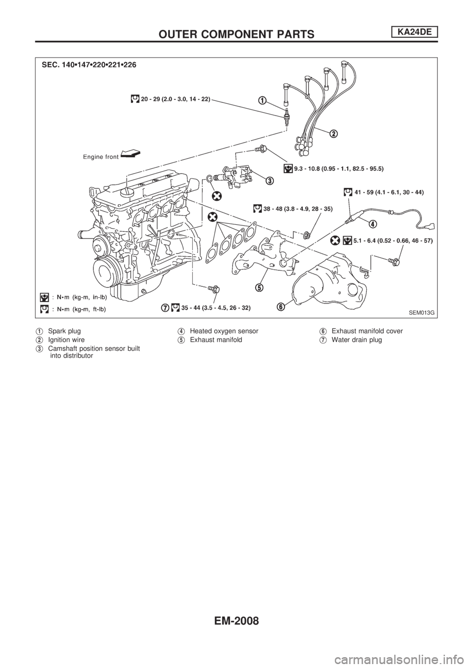
V1Spark plug
V2Ignition wire
V3Camshaft position sensor built
into distributor
V4Heated oxygen sensor
V5Exhaust manifoldV6Exhaust manifold cover
V7Water drain plug
SEM013G
OUTER COMPONENT PARTSKA24DE
EM-2008
Page 438 of 666
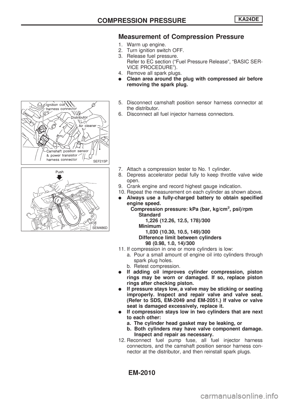
Measurement of Compression Pressure
1. Warm up engine.
2. Turn ignition switch OFF.
3. Release fuel pressure.
Refer to EC section (ªFuel Pressure Releaseº, ªBASIC SER-
VICE PROCEDUREº).
4. Remove all spark plugs.
lClean area around the plug with compressed air before
removing the spark plug.
5. Disconnect camshaft position sensor harness connector at
the distributor.
6. Disconnect all fuel injector harness connectors.
7. Attach a compression tester to No. 1 cylinder.
8. Depress accelerator pedal fully to keep throttle valve wide
open.
9. Crank engine and record highest gauge indication.
10. Repeat the measurement on each cylinder as shown above.
lAlways use a fully-charged battery to obtain specified
engine speed.
Compression pressure: kPa (bar, kg/cm
2, psi)/rpm
Standard
1,226 (12.26, 12.5, 178)/300
Minimum
1,030 (10.30, 10.5, 149)/300
Difference limit between cylinders
98 (0.98, 1.0, 14)/300
11. If compression in one or more cylinders is low:
a. Pour a small amount of engine oil into cylinders through
spark plug holes.
b. Retest compression.
lIf adding oil improves cylinder compression, piston
rings may be worn or damaged. If so, replace piston
rings after checking piston.
lIf pressure stays low, a valve may be sticking or seating
improperly. Inspect and repair valve and valve seat.
(Refer to SDS, EM-2049 and EM-2051.) If valve or valve
seat is damaged excessively, replace it.
lIf compression stays low in two cylinders that are next
to each other:
a. The cylinder head gasket may be leaking, or
b. Both cylinders may have valve component damage.
Inspect and repair as necessary.
12. Reconnect fuel pump fuse, all fuel injector harness
connectors, and the camshaft position sensor harness con-
nector at the distributor, and then reinstall spark plugs.
SEF215P
SEM486D
COMPRESSION PRESSUREKA24DE
EM-2010
Page 443 of 666
Removal
CAUTION:
lAfter removing the timing chain, do not turn crankshaft
and camshaft separately, or valves will strike piston
heads.
lWhen installing chain tensioners or other sliding parts,
lubricate contacting surfaces with new engine oil.
lApply new engine oil to bolt threads and seat surfaces
when installing camshaft sprockets and crankshaft pul-
ley.
lDo not spill engine coolant on drive belts.
UPPER TIMING CHAIN
1. Remove air duct assembly.
2. Remove vacuum hoses, electrical harness connectors and
harness clamps.
3. Remove power steering drive belt.
4. Remove power steering pump and position it to one side.
5. Remove power steering pump bracket.
6. Remove idler pulley and bracket as well.
7. Remove ignition wires and spark plugs.
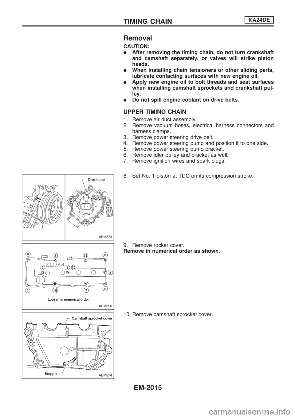
8. Set No. 1 piston at TDC on its compression stroke.
9. Remove rocker cover.
Remove in numerical order as shown.
10. Remove camshaft sprocket cover.
AEM373
AEM356
AEM374
TIMING CHAINKA24DE
EM-2015
Page 496 of 666
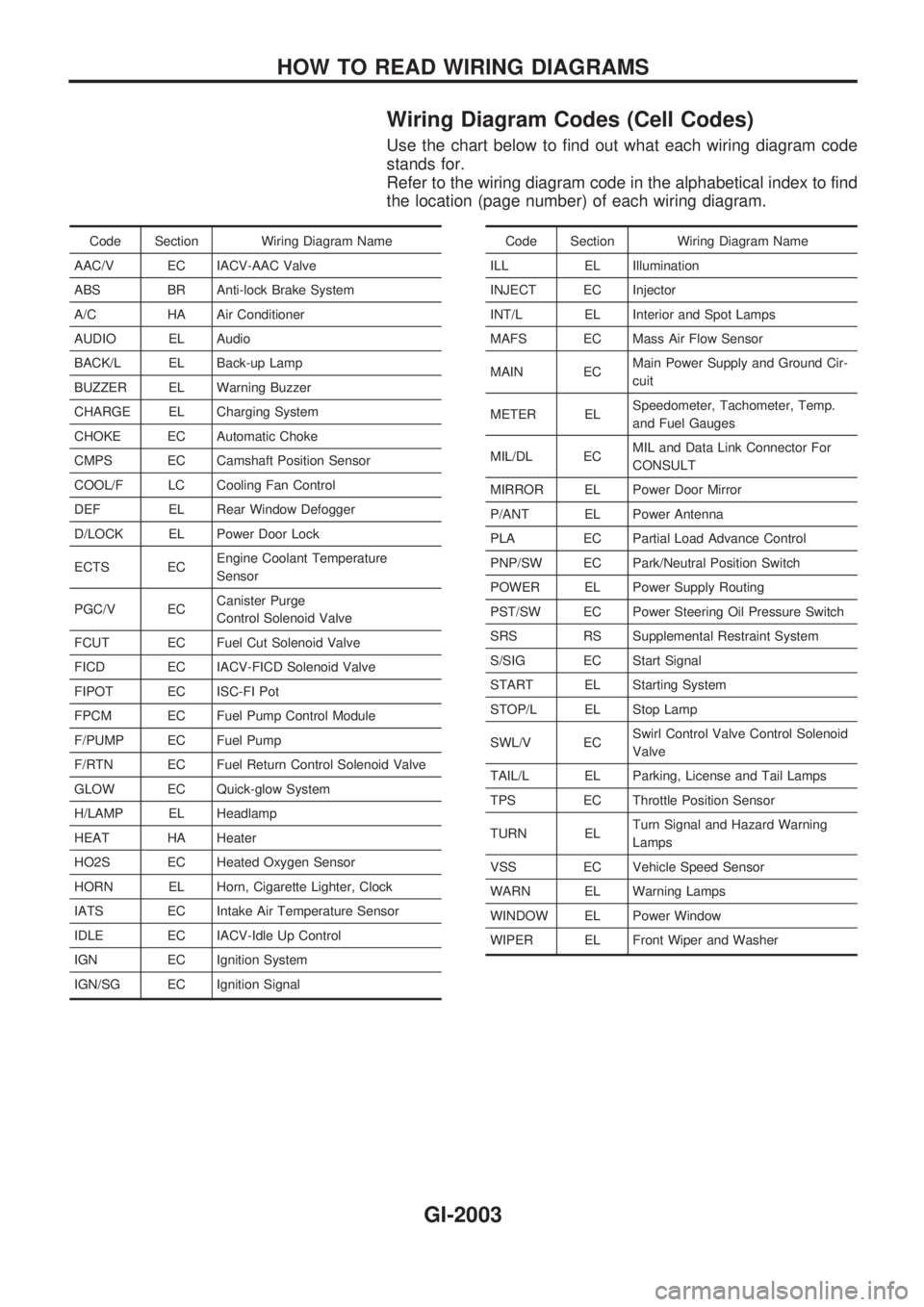
Wiring Diagram Codes (Cell Codes)
Use the chart below to find out what each wiring diagram code
stands for.
Refer to the wiring diagram code in the alphabetical index to find
the location (page number) of each wiring diagram.
Code Section Wiring Diagram Name
AAC/V EC IACV-AAC Valve
ABS BR Anti-lock Brake System
A/C HA Air Conditioner
AUDIO EL Audio
BACK/L EL Back-up Lamp
BUZZER EL Warning Buzzer
CHARGE EL Charging System
CHOKE EC Automatic Choke
CMPS EC Camshaft Position Sensor
COOL/F LC Cooling Fan Control
DEF EL Rear Window Defogger
D/LOCK EL Power Door Lock
ECTS ECEngine Coolant Temperature
Sensor
PGC/V ECCanister Purge
Control Solenoid Valve
FCUT EC Fuel Cut Solenoid Valve
FICD EC IACV-FICD Solenoid Valve
FIPOT EC ISC-FI Pot
FPCM EC Fuel Pump Control Module
F/PUMP EC Fuel Pump
F/RTN EC Fuel Return Control Solenoid Valve
GLOW EC Quick-glow System
H/LAMP EL Headlamp
HEAT HA Heater
HO2S EC Heated Oxygen Sensor
HORN EL Horn, Cigarette Lighter, Clock
IATS EC Intake Air Temperature Sensor
IDLE EC IACV-Idle Up Control
IGN EC Ignition System
IGN/SG EC Ignition SignalCode Section Wiring Diagram Name
ILL EL Illumination
INJECT EC Injector
INT/L EL Interior and Spot Lamps
MAFS EC Mass Air Flow Sensor
MAIN ECMain Power Supply and Ground Cir-
cuit
METER ELSpeedometer, Tachometer, Temp.
and Fuel Gauges
MIL/DL ECMIL and Data Link Connector For
CONSULT
MIRROR EL Power Door Mirror
P/ANT EL Power Antenna
PLA EC Partial Load Advance Control
PNP/SW EC Park/Neutral Position Switch
POWER EL Power Supply Routing
PST/SW EC Power Steering Oil Pressure Switch
SRS RS Supplemental Restraint System
S/SIG EC Start Signal
START EL Starting System
STOP/L EL Stop Lamp
SWL/V ECSwirl Control Valve Control Solenoid
Valve
TAIL/L EL Parking, License and Tail Lamps
TPS EC Throttle Position Sensor
TURN ELTurn Signal and Hazard Warning
Lamps
VSS EC Vehicle Speed Sensor
WARN EL Warning Lamps
WINDOW EL Power Window
WIPER EL Front Wiper and Washer
HOW TO READ WIRING DIAGRAMS
GI-2003
Page 523 of 666
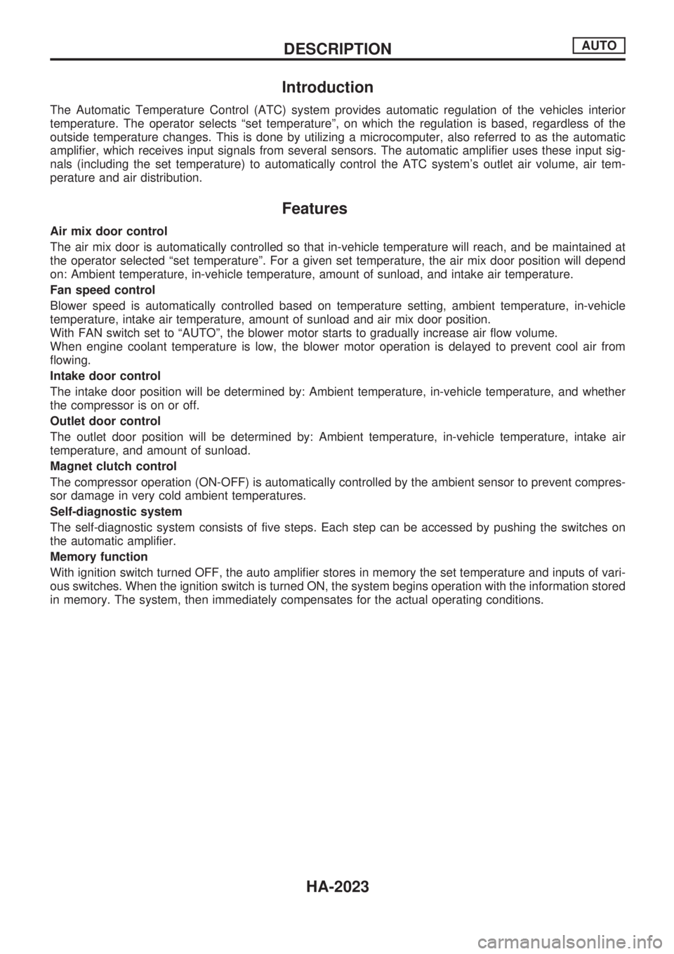
Introduction
The Automatic Temperature Control (ATC) system provides automatic regulation of the vehicles interior
temperature. The operator selects ªset temperatureº, on which the regulation is based, regardless of the
outside temperature changes. This is done by utilizing a microcomputer, also referred to as the automatic
amplifier, which receives input signals from several sensors. The automatic amplifier uses these input sig-
nals (including the set temperature) to automatically control the ATC system's outlet air volume, air tem-
perature and air distribution.
Features
Air mix door control
The air mix door is automatically controlled so that in-vehicle temperature will reach, and be maintained at
the operator selected ªset temperatureº. For a given set temperature, the air mix door position will depend
on: Ambient temperature, in-vehicle temperature, amount of sunload, and intake air temperature.
Fan speed control
Blower speed is automatically controlled based on temperature setting, ambient temperature, in-vehicle
temperature, intake air temperature, amount of sunload and air mix door position.
With FAN switch set to ªAUTOº, the blower motor starts to gradually increase air flow volume.
When engine coolant temperature is low, the blower motor operation is delayed to prevent cool air from
flowing.
Intake door control
The intake door position will be determined by: Ambient temperature, in-vehicle temperature, and whether
the compressor is on or off.
Outlet door control
The outlet door position will be determined by: Ambient temperature, in-vehicle temperature, intake air
temperature, and amount of sunload.
Magnet clutch control
The compressor operation (ON-OFF) is automatically controlled by the ambient sensor to prevent compres-
sor damage in very cold ambient temperatures.
Self-diagnostic system
The self-diagnostic system consists of five steps. Each step can be accessed by pushing the switches on
the automatic amplifier.
Memory function
With ignition switch turned OFF, the auto amplifier stores in memory the set temperature and inputs of vari-
ous switches. When the ignition switch is turned ON, the system begins operation with the information stored
in memory. The system, then immediately compensates for the actual operating conditions.
DESCRIPTIONAUTO
HA-2023
Page 534 of 666
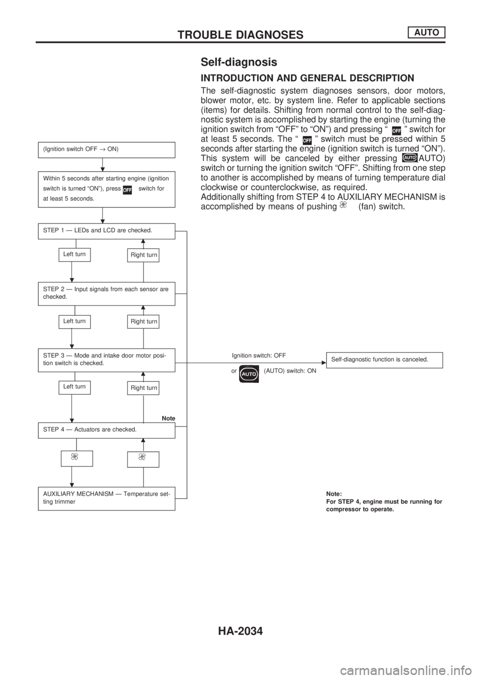
Self-diagnosis
INTRODUCTION AND GENERAL DESCRIPTION
The self-diagnostic system diagnoses sensors, door motors,
blower motor, etc. by system line. Refer to applicable sections
(items) for details. Shifting from normal control to the self-diag-
nostic system is accomplished by starting the engine (turning the
ignition switch from ªOFFº to ªONº) and pressing ª
º switch for
at least 5 seconds. The ª
º switch must be pressed within 5
seconds after starting the engine (ignition switch is turned ªONº).
This system will be canceled by either pressing
(AUTO)
switch or turning the ignition switch ªOFFº. Shifting from one step
to another is accomplished by means of turning temperature dial
clockwise or counterclockwise, as required.
Additionally shifting from STEP 4 to AUXILIARY MECHANISM is
accomplished by means of pushing
(fan) switch.
(Ignition switch OFF®ON)
Within 5 seconds after starting engine (ignition
switch is turned ªONº), press
switch for
at least 5 seconds.
STEP 1 Ð LEDs and LCD are checked.
m
Left turnRight turn
STEP 2 Ð Input signals from each sensor are
checked.
m
Left turnRight turn
STEP 3 Ð Mode and intake door motor posi-
tion switch is checked.Ignition switch: OFFc
or(AUTO) switch: ONSelf-diagnostic function is canceled.m
Left turnRight turn
Note
STEP 4 Ð Actuators are checked.
m
AUXILIARY MECHANISM Ð Temperature set-
ting trimmerNote:
For STEP 4, engine must be running for
compressor to operate.
.
.
.
.
.
.
TROUBLE DIAGNOSESAUTO
HA-2034
Page 535 of 666
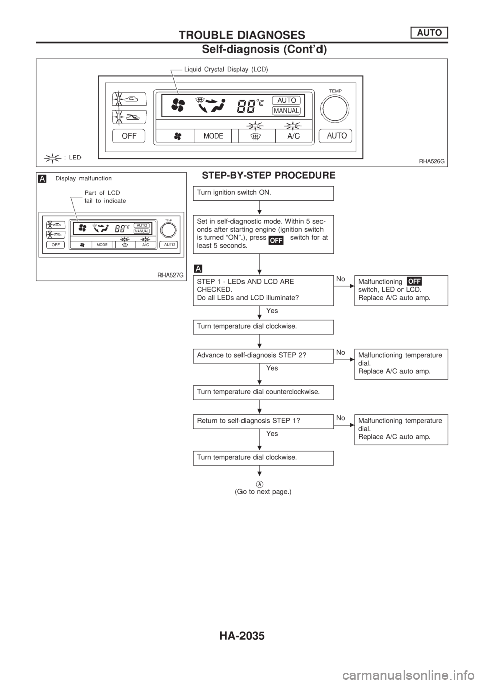
STEP-BY-STEP PROCEDURE
Turn ignition switch ON.
Set in self-diagnostic mode. Within 5 sec-
onds after starting engine (ignition switch
is turned ªONº.), press
switch for at
least 5 seconds.
STEP 1 - LEDs AND LCD ARE
CHECKED.
Do all LEDs and LCD illuminate?
Yes
cNo
Malfunctioning
switch, LED or LCD.
Replace A/C auto amp.
Turn temperature dial clockwise.
Advance to self-diagnosis STEP 2?
Yes
cNo
Malfunctioning temperature
dial.
Replace A/C auto amp.
Turn temperature dial counterclockwise.
Return to self-diagnosis STEP 1?
Yes
cNo
Malfunctioning temperature
dial.
Replace A/C auto amp.
Turn temperature dial clockwise.
VA(Go to next page.)
RHA526G
RHA527G
.
.
.
.
.
.
.
.
TROUBLE DIAGNOSESAUTO
Self-diagnosis (Cont'd)
HA-2035