Page 538 of 666
VC
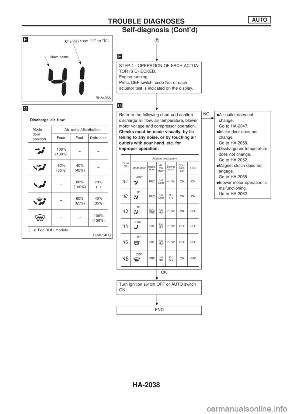
STEP 4 - OPERATION OF EACH ACTUA-
TOR IS CHECKED.
Engine running.
Press DEF switch, code No. of each
actuator test is indicated on the display.
Refer to the following chart and confirm
discharge air flow, air temperature, blower
motor voltage and compressor operation.
Checks must be made visually, by lis-
tening to any noise, or by touching air
outlets with your hand, etc. for
improper operation.
OK
cNGlAir outlet does not
change.
Go to HA-2047.
lIntake door does not
change.
Go to HA-2058.
lDischarge air temperature
does not change.
Go to HA-2052.
lMagnet clutch does not
engage.
Go to HA-2068.
lBlower motor operation is
malfunctioning.
Go to HA-2062.
Turn ignition switch OFF or AUTO switch
ON.
END
Code
No.Actuator test pattern
Mode doorIntake
doorAir
mix
doorBlower
motorCom-
pres-
sorFICD
VENTRECFull
Cold4-5V ON ON
B/LRECFull
Cold9-
11VON ON
B/L20%
FREFull
Hot7-9V ON OFF
FOOTFREFull
Hot7 - 9V OFF OFF
D/F
FREFull
Hot7 - 9V OFF OFF
DEFFREFull
Hot10 -
12VON OFF
RHA495A
RHA654FG
.
.
.
.
TROUBLE DIAGNOSESAUTO
Self-diagnosis (Cont'd)
HA-2038
Page 541 of 666
Operational Check
The purpose of the operational check is to confirm that the sys-
tem operates properly.
CONDITIONS
lEngine running and at normal operating temperature.
PROCEDURE
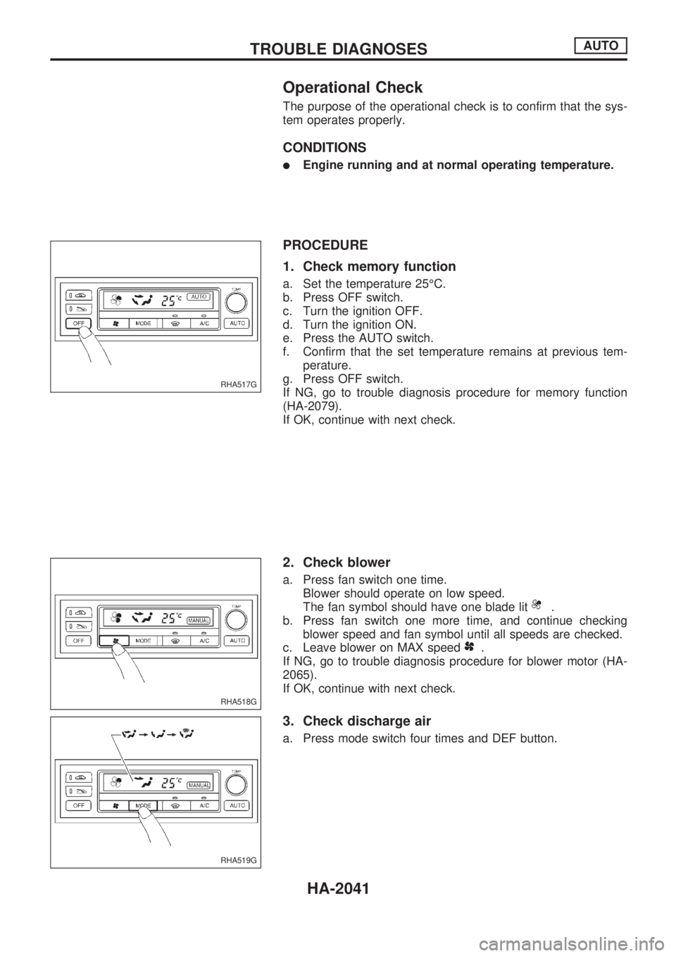
1. Check memory function
a. Set the temperature 25ÉC.
b. Press OFF switch.
c. Turn the ignition OFF.
d. Turn the ignition ON.
e. Press the AUTO switch.
f. Confirm that the set temperature remains at previous tem-
perature.
g. Press OFF switch.
If NG, go to trouble diagnosis procedure for memory function
(HA-2079).
If OK, continue with next check.
2. Check blower
a. Press fan switch one time.
Blower should operate on low speed.
The fan symbol should have one blade lit
.
b. Press fan switch one more time, and continue checking
blower speed and fan symbol until all speeds are checked.
c. Leave blower on MAX speed
.
If NG, go to trouble diagnosis procedure for blower motor (HA-
2065).
If OK, continue with next check.
3. Check discharge air
a. Press mode switch four times and DEF button.
RHA517G
RHA518G
RHA519G
TROUBLE DIAGNOSESAUTO
HA-2041
Page 546 of 666
MAIN POWER SUPPLY AND GROUND CIRCUIT
CHECK
Power Supply Circuit Check
Check power supply circuit for air conditioner system.
Refer to EL section (ªWiring Diagramº, ªPOWER SUPPLY
ROUTINGº).
DIAGNOSTIC PROCEDURE
SYMPTOM: A/C system does not come on.
Auto amp. check
Check power supply circuit for auto amp. with ignition switch ON.
Measure voltage across terminal Nos.
V1,V2,V20and body
ground.
Voltmeter terminal
Voltage
Å@
V1
Body ground Approx. 12VV2
V20
RHA632G
RHA633GA
TROUBLE DIAGNOSESAUTO
A/C System (Cont'd)
HA-2046
Page 549 of 666
DIAGNOSTIC PROCEDURE
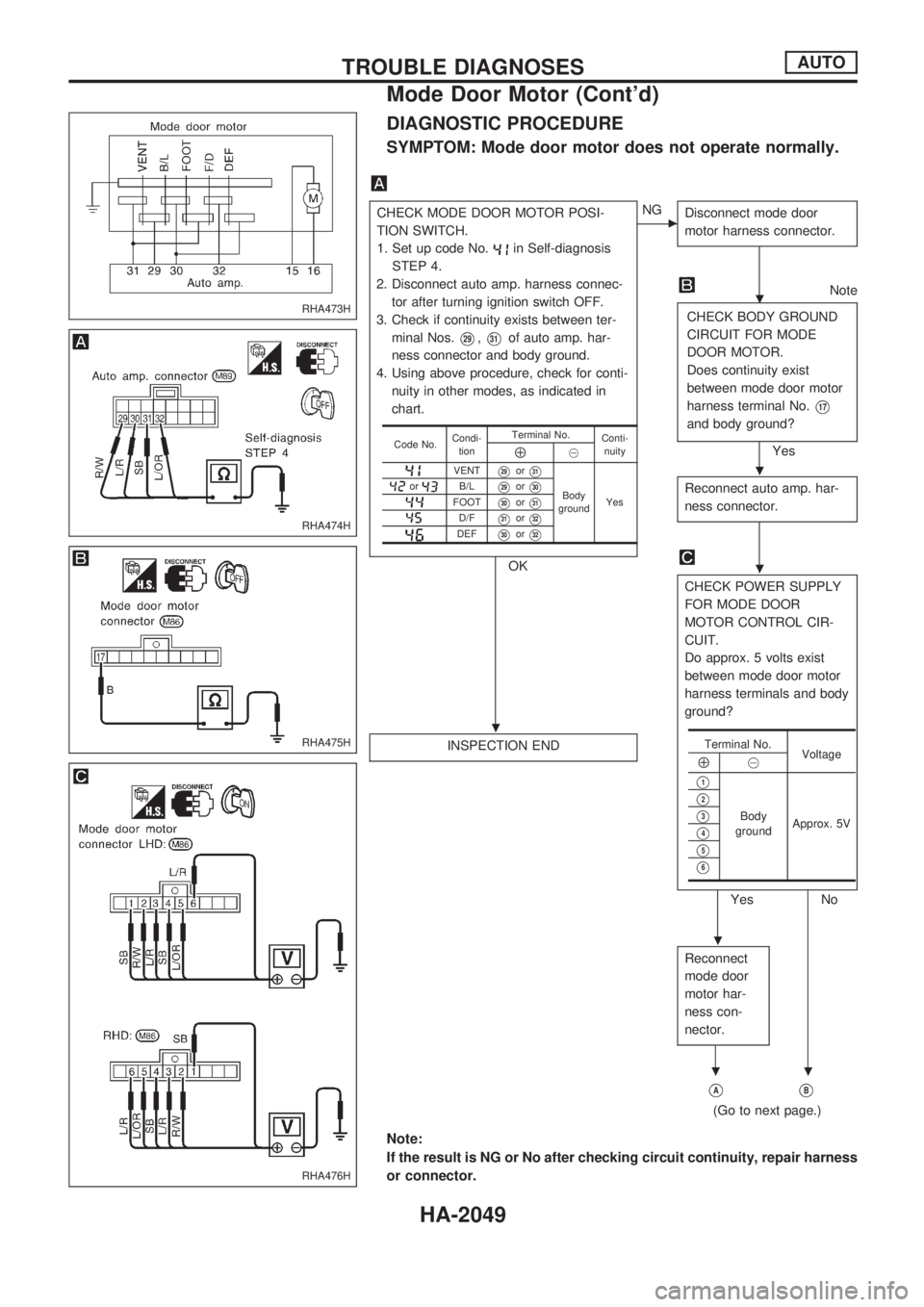
SYMPTOM: Mode door motor does not operate normally.
CHECK MODE DOOR MOTOR POSI-
TION SWITCH.
1. Set up code No.
in Self-diagnosis
STEP 4.
2. Disconnect auto amp. harness connec-
tor after turning ignition switch OFF.
3. Check if continuity exists between ter-
minal Nos.
V29,V31of auto amp. har-
ness connector and body ground.
4. Using above procedure, check for conti-
nuity in other modes, as indicated in
chart.
OK
cNG
Disconnect mode door
motor harness connector.
Note
CHECK BODY GROUND
CIRCUIT FOR MODE
DOOR MOTOR.
Does continuity exist
between mode door motor
harness terminal No.
V17
and body ground?
Yes
Reconnect auto amp. har-
ness connector.
CHECK POWER SUPPLY
FOR MODE DOOR
MOTOR CONTROL CIR-
CUIT.
Do approx. 5 volts exist
between mode door motor
harness terminals and body
ground?
Yes No INSPECTION END
Reconnect
mode door
motor har-
ness con-
nector.
VAVB
(Go to next page.)
Code No.Condi-
tionTerminal No.
Conti-
nuityÅ@
VENTV29orV31
Body
groundYesorB/LV29orV30
FOOTV30orV31
D/FV31orV32
DEFV30orV32
Terminal No.
Voltage
Å@
V1
Body
groundApprox. 5VV2
V3
V4
V5
V6
Note:
If the result is NG or No after checking circuit continuity, repair harness
or connector.
RHA473H
RHA474H
RHA475H
RHA476H
.
.
.
.
.
..
TROUBLE DIAGNOSESAUTO
Mode Door Motor (Cont'd)
HA-2049
Page 584 of 666
COMPONENT INSPECTION
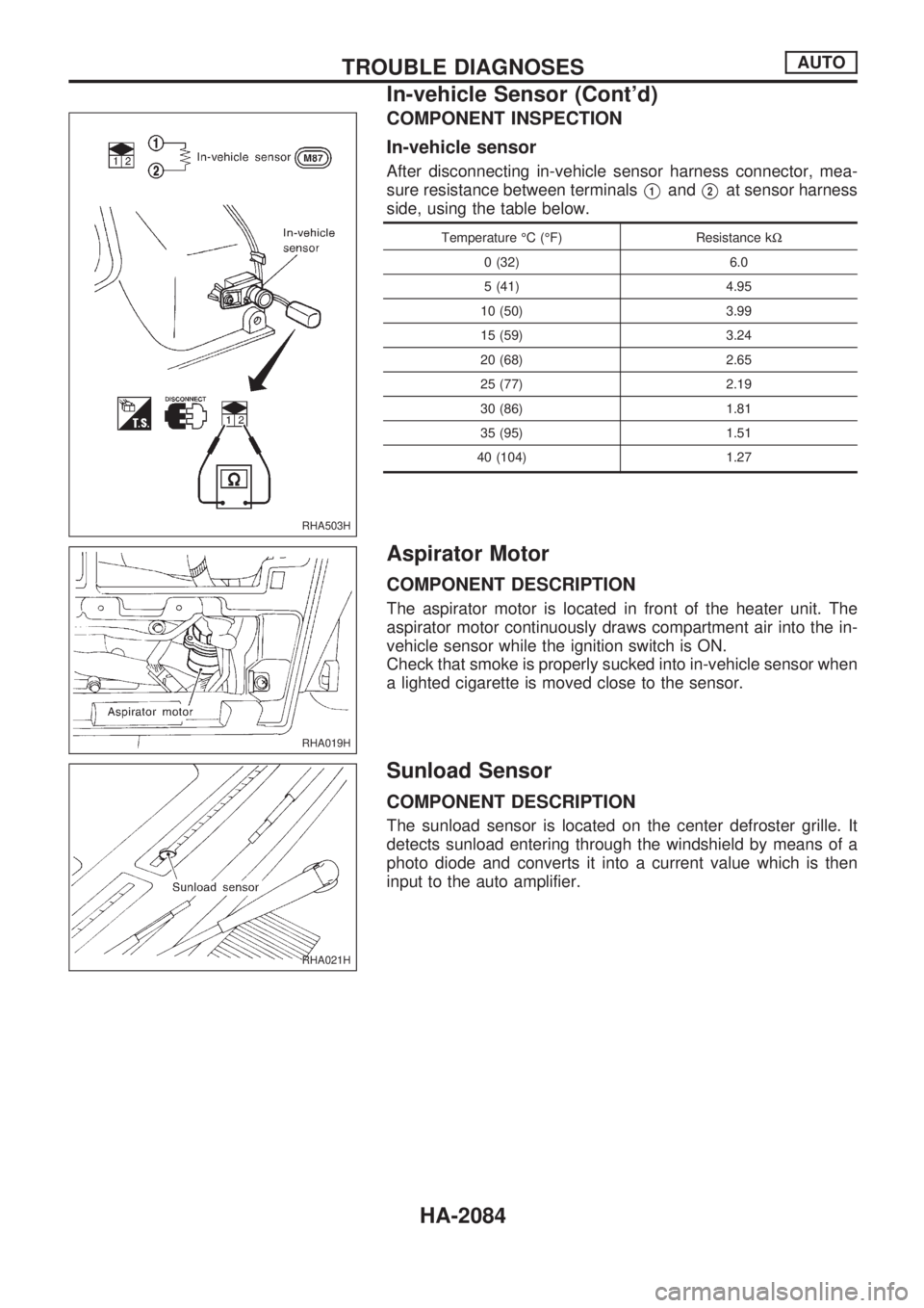
In-vehicle sensor
After disconnecting in-vehicle sensor harness connector, mea-
sure resistance between terminals
V1andV2at sensor harness
side, using the table below.
Temperature ÉC (ÉF) Resistance kW
0 (32) 6.0
5 (41) 4.95
10 (50) 3.99
15 (59) 3.24
20 (68) 2.65
25 (77) 2.19
30 (86) 1.81
35 (95) 1.51
40 (104) 1.27
Aspirator Motor
COMPONENT DESCRIPTION
The aspirator motor is located in front of the heater unit. The
aspirator motor continuously draws compartment air into the in-
vehicle sensor while the ignition switch is ON.
Check that smoke is properly sucked into in-vehicle sensor when
a lighted cigarette is moved close to the sensor.
Sunload Sensor
COMPONENT DESCRIPTION
The sunload sensor is located on the center defroster grille. It
detects sunload entering through the windshield by means of a
photo diode and converts it into a current value which is then
input to the auto amplifier.
RHA503H
RHA019H
RHA021H
TROUBLE DIAGNOSESAUTO
In-vehicle Sensor (Cont'd)
HA-2084
Page 626 of 666
Precautions for SRS ``AIR BAG'' and ``SEAT
BELT PRE-TENSIONER'' Service
lDo not use electrical test equipment to check SRS circuits unless instructed to in this Service Manual.
lBefore servicing the SRS, turn ignition switch ``OFF'', disconnect both battery cables and wait at least
3 minutes.
For approximately 3 minutes after the cables are removed, it is still possible for the air bag to deploy.
Therefore, do not work on any SRS connectors or wires until at least 3 minutes have passed.
lDiagnosis sensor unit must always be installed with their arrow marks ``S'' pointing towards the front of
the vehicle for proper operation. Also check diagnosis sensor unit for cracks, deformities or rust before
installation and replace as required.
lThe spiral cable must be aligned with the neutral position since its rotations are limited. Do not attempt
to turn steering wheel or column after removal of steering gear.
lHandle air bag module carefully. Always place driver and passenger air bag modules with the pad side
facing upward.
lConduct self-diagnosis to check entire SRS for proper function after replacing any components.
lAfter air bag inflates, the front instrument panel assembly should be replaced if damaged.
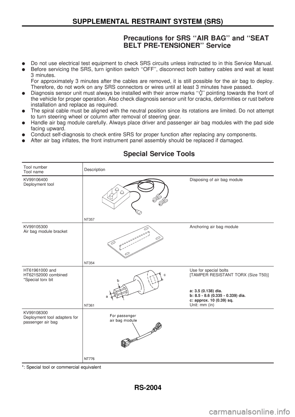
Special Service Tools
Tool number
Tool nameDescription
KV99106400
Deployment tool
NT357
Disposing of air bag module
KV99105300
Air bag module bracket
NT354
Anchoring air bag module
HT61961000 and
HT62152000 combined
*Special torx bit
NT361
Use for special bolts
[TAMPER RESISTANT TORX (Size T50)]
a: 3.5 (0.138) dia.
b: 8.5 - 8.6 (0.335 - 0.339) dia.
c: approx. 10 (0.39) sq.
Unit: mm (in)
KV99108300
Deployment tool adapters for
passenger air bag
NT776
*: Special tool or commercial equivalent
SUPPLEMENTAL RESTRAINT SYSTEM (SRS)
RS-2004
Page 627 of 666
Commercial Service Tool
Tool name Description Specification
Tamper resistant torx
socket
NT757
Size: T30
Description
The air bag deploys if the diagnosis sensor unit activates while the ignition switch is in the ``ON'' or ``START''
position.
NRS087
SUPPLEMENTAL RESTRAINT SYSTEM (SRS)
RS-2005
Page 628 of 666
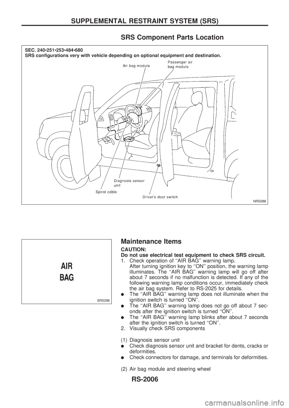
SRS Component Parts Location
Maintenance Items
CAUTION:
Do not use electrical test equipment to check SRS circuit.
1. Check operation of ``AIR BAG'' warning lamp.
After turning ignition key to ``ON'' position, the warning lamp
illuminates. The ``AIR BAG'' warning lamp will go off after
about 7 seconds if no malfunction is detected. If any of the
following warning lamp conditions occur, immediately check
the air bag system. Refer to RS-2025 for details.
lThe ``AIR BAG'' warning lamp does not illuminate when the
ignition switch is turned ``ON''.
lThe ``AIR BAG'' warning lamp does not go off about 7 sec-
onds after the ignition switch is turned ``ON''.
lThe ``AIR BAG'' warning lamp blinks after about 7 seconds
after the ignition switch is turned ``ON''.
2. Visually check SRS components
(1) Diagnosis sensor unit
lCheck diagnosis sensor unit and bracket for dents, cracks or
deformities.
lCheck connectors for damage, and terminals for deformities.
(2) Air bag module and steering wheel
NRS088
SRS296
SUPPLEMENTAL RESTRAINT SYSTEM (SRS)
RS-2006