1999 NISSAN PICK-UP sensor
[x] Cancel search: sensorPage 629 of 666
lRemove air bag module from steering wheel, instrument
panel or seat back. Check harness cover and connectors for
damage, terminals for deformities, and harness for binding.
lInstall driver air bag module to steering wheel to check fit or
alignment with the wheel.
lCheck steering wheel for excessive free play.
lInstall passenger air bag module to instrument panel to
check fit or alignment with the instrument panel.
(3) Spiral cable
lCheck spiral cable for dents, cracks, or deformities.
lCheck connectors and protective tape for damage.
lCheck steering wheel for noise, binding or heavy operation.
(4) Main harness and air bag harness
lCheck connectors for poor connections, damage, and termi-
nals for deformities.
lCheck harnesses for binding, chafing or cut.
CAUTION:
Replace previously used special bolts and ground bolt with
new ones.
Removal and Installation Ð Diagnosis
Sensor Unit
CAUTION:
lBefore servicing SRS, turn the ignition switch off, disconnect both battery cables and wait at least
3 minutes.
lDo not use old special bolts and nuts coated with bonding agent after removal; replace with new
ones.
lCheck diagnosis sensor unit for proper installation.
lCheck diagnosis sensor unit to ensure it is free of deformities, dents, cracks or rust. If it shows
any visible signs of damage, replace it with a new one.
lCheck diagnosis sensor unit brackets to ensure they are free of deformities and rust.
lAfter replacement of diagnosis sensor unit, check SRS function and perform self-diagnosis for
SRS. Refer to ``Self-diagnosis'' for details. (RS-2025)
lDo not attempt to disassemble diagnosis sensor unit.
lReplace diagnosis sensor unit and if it has been dropped or sustained an impact.
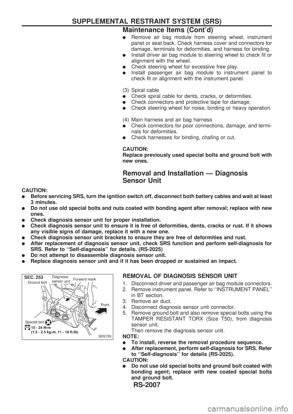
REMOVAL OF DIAGNOSIS SENSOR UNIT
1. Disconnect driver and passenger air bag module connectors.
2. Remove instrument panel. Refer to ``INSTRUMENT PANEL''
in BT section.
3. Remove air duct.
4. Disconnect diagnosis sensor unit connector.
5. Remove ground bolt and also remove special bolts using the
TAMPER RESISTANT TORX (Size T50), from diagnosis
sensor unit.
Then remove the diagnosis sensor unit.
NOTE:
lTo install, reverse the removal procedure sequence.
lAfter replacement, perform self-diagnosis for SRS. Refer
to ``Self-diagnosis'' for details (RS-2025).
CAUTION:
lDo not use old special bolts and ground bolt coated with
bonding agent; replace with new coated special bolts
and ground bolt.
SRS729
SUPPLEMENTAL RESTRAINT SYSTEM (SRS)
Maintenance Items (Cont'd)
RS-2007
Page 637 of 666
Trouble Diagnoses Introduction
CAUTION:
lDo not use electrical test equipment to check SRS harness connectors unless instructed to in
this Service Manual. SRS wiring harnesses can be identified by yellow harness protector or yel-
low insulation tape before the harness connectors.
lDo not attempt to repair, splice or modify the SRS wiring harness. If the harness is damaged,
replace it with a new one.
lKeep ground portion clean.
DIAGNOSIS FUNCTION
The SRS self-diagnosis results can be read by using ``AIR BAG'' warning lamp and/or CONSULT. The
reading of these results is accomplished using one of two modes Ð ``User mode'' and ``Diagnosis mode''.
The User mode is exclusively prepared for the customer (driver). This mode warns the driver of a system
malfunction through the operation of the ``AIR BAG'' warning lamp.
The Diagnosis mode allows the technician to locate and inspect the malfunctioning part.
The mode applications for the ``AIR BAG'' warning lamp and CONSULT are as follows:
User mode Diagnosis mode Display type
``AIR BAG'' warning lamp X X ON-OFF operation
DIAGNOSIS MODE FOR CONSULT
l``SELF-DIAG [CURRENT]''
A current Self-diagnosis result (also indicated by the warning lamp flashes in the Diagnosis mode) is
displayed on the CONSULT screen in real time. This refers to a malfunctioning part requiring repairs.
l``SELF-DIAG [PAST]''
Diagnosis results previously stored in the memory are displayed on the CONSULT screen. The stored
results are not erased until memory erasing is executed.
l``TROUBLE DIAG RECORD''
With TROUBLE DIAG RECORD, diagnosis results previously erased by a reset operation can be dis-
played on the CONSULT screen.
l``ECU DISCRIMINATED NO.''
The diagnosis sensor unit for each vehicle model is assigned with its own, individual classification number.
This number will be displayed on the CONSULT screen, as shown at left. When replacing the diagnosis
sensor unit, refer to the part number for the compatibility. After installation, replacement with a correct unit
can be checked by confirming this classification number on the CONSULT screen. The diagnosis sensor
unit classification number varies depending on SRS configuration.
For NISSAN MODEL D22, the diagnosis sensor unit classification numbers assigned are as follows.
MODEL ECU DISCRIMINATED NO.
Single air bag 5A0B
Dual air bag 5A0A
TROUBLE DIAGNOSES Ð Supplemental Restraint System (SRS)
RS-2015
Page 647 of 666
Self-diagnosis
DIAGNOSTIC PROCEDURE 1 (without CONSULT)
Checking SRS operation by using ``AIR BAG'' warning lamp
Ð User mode
1. After turning ignition switch from ``OFF'' to ``ON'', ``AIR BAG''
warning lamp operates.
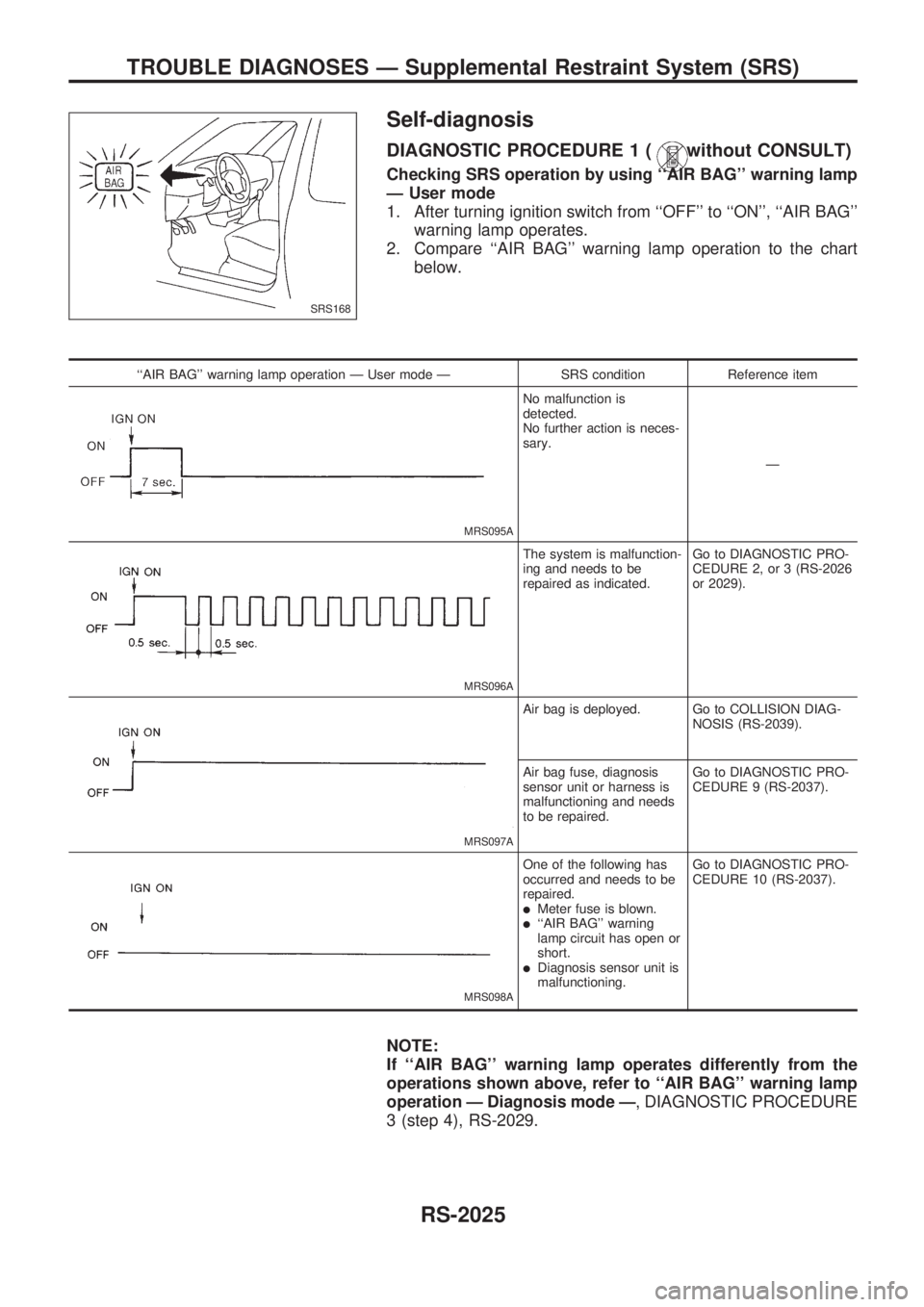
2. Compare ``AIR BAG'' warning lamp operation to the chart
below.
``AIR BAG'' warning lamp operation Ð User mode Ð SRS condition Reference item
MRS095A
No malfunction is
detected.
No further action is neces-
sary.
Ð
MRS096A
The system is malfunction-
ing and needs to be
repaired as indicated.Go to DIAGNOSTIC PRO-
CEDURE 2, or 3 (RS-2026
or 2029).
MRS097A
Air bag is deployed. Go to COLLISION DIAG-
NOSIS (RS-2039).
Air bag fuse, diagnosis
sensor unit or harness is
malfunctioning and needs
to be repaired.Go to DIAGNOSTIC PRO-
CEDURE 9 (RS-2037).
MRS098A
One of the following has
occurred and needs to be
repaired.
lMeter fuse is blown.l``AIR BAG'' warning
lamp circuit has open or
short.
lDiagnosis sensor unit is
malfunctioning.Go to DIAGNOSTIC PRO-
CEDURE 10 (RS-2037).
NOTE:
If ``AIR BAG'' warning lamp operates differently from the
operations shown above, refer to ``AIR BAG'' warning lamp
operation Ð Diagnosis mode Ð, DIAGNOSTIC PROCEDURE
3 (step 4), RS-2029.
SRS168
TROUBLE DIAGNOSES Ð Supplemental Restraint System (SRS)
RS-2025
Page 650 of 666
![NISSAN PICK-UP 1999 Repair Manual CONSULT DIAGNOSTIC CODE CHART (``SELF-DIAG [CURRENT])
Diagnostic item ExplanationRepair order
Recheck SRS at each
replacement.
NO SELF DIAGNOSTIC
FAILURE INDICATEDWhen malfunction is indicated
by th NISSAN PICK-UP 1999 Repair Manual CONSULT DIAGNOSTIC CODE CHART (``SELF-DIAG [CURRENT])
Diagnostic item ExplanationRepair order
Recheck SRS at each
replacement.
NO SELF DIAGNOSTIC
FAILURE INDICATEDWhen malfunction is indicated
by th](/manual-img/5/57373/w960_57373-649.png)
CONSULT DIAGNOSTIC CODE CHART (``SELF-DIAG [CURRENT]'')
Diagnostic item ExplanationRepair order
Recheck SRS at each
replacement.
NO SELF DIAGNOSTIC
FAILURE INDICATEDWhen malfunction is indicated
by the ``AIR BAG'' warning lamp
in User mode
lLow battery voltage (Less
than 9V)lGo to DIAGNOSTIC PROCE-
DURE 4 (RS-2030) after
charging battery.
lSelf-diagnostic result ``SELF-
DIAG [PAST]'' (previously
stored in the memory) might
not be erased after repair.
lIntemittent malfunction has
been detected in the past.
lGo to DIAGNOSTIC PROCE-
DURE 6 (RS-2034).
lNo malfunction is detected.lGo to DIAGNOSTIC PROCE-
DURE 4 (RS-2030).
AIRBAG MODULE
[OPEN]
lDriver's air bag module circuit is open. (including the spiral cable) 1. Visually check the wiring har-
ness connection.
2. Replace the harness if it has
visible damage.
3. Replace the spiral cable.
4. Replace driver's air bag mod-
ule.
(Before disposal of it, it must
be deployed.)
5. Replace the diagnosis sensor
unit.
6. Replace the related harness. AIRBAG MODULE
[VB-SHORT]
lDriver's air bag module circuit is shorted to some power supply
circuit. (including the spiral cable)
AIRBAG MODULE
[GND-SHORT]
lDriver's air bag module circuit is shorted to ground. (including the
spiral cable)
AIRBAG MODULE
[SHORT]
lDriver's air bag module circuits are shorted to each other.
ASSIST A/B MODULE
[VB-SHORT]
lFront passenger air bag module circuit is shorted to some power
supply circuit.1. Visually check the wiring har-
ness connection.
2. Replace the harness if it has
visible damage.
3. Replace front passenger air
bag module.
(Before disposal of it, it must
be deployed.)
4. Replace the diagnosis sensor
unit.
5. Replace the related harness. ASSIST A/B MODULE
[OPEN]
lFront passenger air bag module circuit is open.
ASSIST A/B MODULE
[GND-SHORT]
lFront passenger air bag module circuit is shorted to ground.
ASSIST A/B MODULE
[SHORT]
lFront passenger air bag module circuits are shorted to each
other.
CONTROL UNIT
lDiagnosis sensor unit is malfunctioning. 1. Visually check the wiring har-
ness connections.
2. Replace the harness if it has
visible damage.
3. Replace the diagnosis sensor
unit.
4. Replace the related harness.
* Follow the procedures in numerical order when repairing malfunctioning parts. Confirm whether malfunction is eliminated
using the air bag warning lamp or CONSULT each time repair is finished. If malfunction is still observed, proceed to the
next step. When malfunction is eliminated, further repair work is not required.
TROUBLE DIAGNOSES Ð Supplemental Restraint System (SRS)
Self-diagnosis (Cont'd)
RS-2028
Page 652 of 666
AIR BAG WARNING LAMP FLASH CODE CHART (DIAGNOSIS MODE)
Warning
lampFlash codeV0d
(# of flashes)ExplanationRepair order
``Recheck SRS at each replacement.''
``AIR BAG'' warning lamp
0lDiagnosis results (previously stored in the
memory) might not be erased after repair.
lIntermittent malfunction has been detected in
the past.Go to DIAGNOSTIC PROCEDURE 7 (RS-2034).
2 The driver's air bag module circuit is malfunction-
ing.1. Visually check the wiring harness connections.
2. Replace the harness if it has visible damage.
3. Replace the spiral cable.
4. Replace the driver's air bag module.
(Before disposing of it, it must be deployed.)
5. Replace the diagnosis sensor unit.
6. Replace the related harness.
7 The diagnosis sensor unit is malfunctioning. 1. Visually check the wiring harness connections.
2. Replace the harness if it has visible damage.
3. Replace the diagnosis sensor unit.
4. Replace the related harness.
8 The front passenger air bag module circuit is
malfunctioning.1. Visually check the wiring harness connections.
2. Replace the harness if it has visible damage.
3. Replace the front passenger air bag module.
(Before disposing of it, it must be deployed.)
4. Replace the diagnosis sensor unit.
5. Replace the related harness.
* Follow the procedures in numerical order when repairing malfunctioning parts. Confirm whether malfunction is eliminated
using the air bag warning lamp or CONSULT each time repair is finished. If malfunction is still observed, proceed to the
next step. When malfunction is eliminated, further repair work is not required.
DIAGNOSTIC PROCEDURE 4 (with CONSULT)
Final checking after repairing SRS by using CONSULT Ð
Diagnosis mode
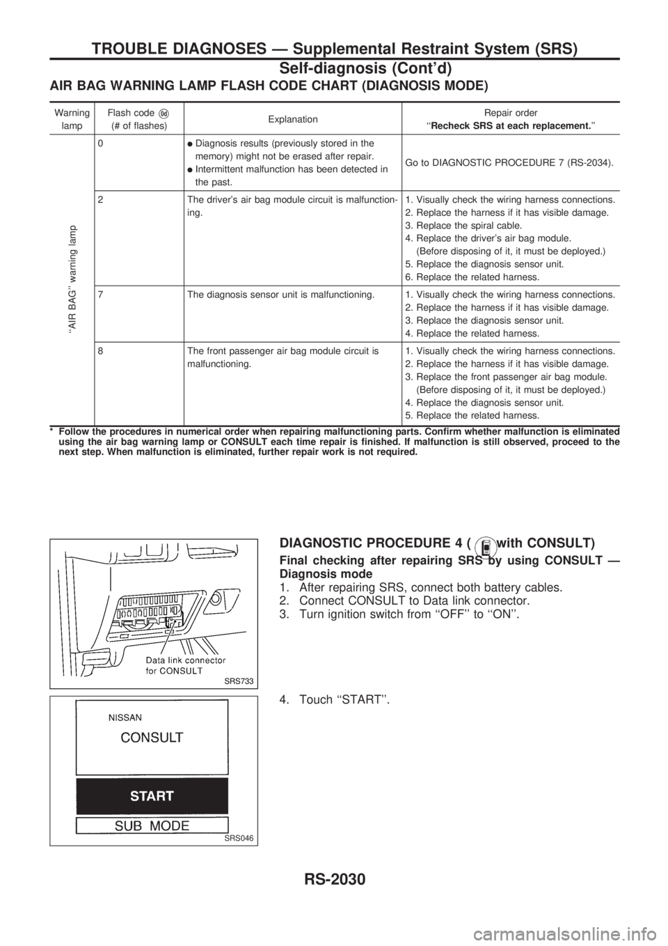
1. After repairing SRS, connect both battery cables.
2. Connect CONSULT to Data link connector.
3. Turn ignition switch from ``OFF'' to ``ON''.
4. Touch ``START''.
SRS733
SRS046
TROUBLE DIAGNOSES Ð Supplemental Restraint System (SRS)
Self-diagnosis (Cont'd)
RS-2030
Page 655 of 666
NOTE:
When diagnosis sensor unit is replaced with new one, ``AIR
BAG'' warning lamp will operate in User mode. Checking
``AIR BAG'' warning lamp operation in Diagnosis mode is
not required. Go to step 6.
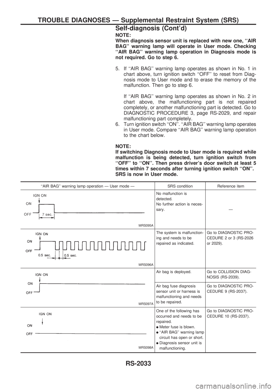
5. If ``AIR BAG'' warning lamp operates as shown in No. 1 in
chart above, turn ignition switch ``OFF'' to reset from Diag-
nosis mode to User mode and to erase the memory of the
malfunction. Then go to step 6.
If ``AIR BAG'' warning lamp operates as shown in No. 2 in
chart above, the malfunctioning part is not repaired
completely, or another malfunctioning part is detected. Go to
DIAGNOSTIC PROCEDURE 3, page RS-2029, and repair
malfunctioning part completely.
6. Turn ignition switch ``ON''. ``AIR BAG'' warning lamp operates
in User mode. Compare ``AIR BAG'' warning lamp operation
to the chart below.
NOTE:
If switching Diagnosis mode to User mode is required while
malfunction is being detected, turn ignition switch from
``OFF'' to ``ON''. Then press driver's door switch at least 5
times within 7 seconds after turning ignition switch ``ON''.
SRS is now in User mode.
``AIR BAG'' warning lamp operation Ð User mode Ð SRS condition Reference item
MRS095A
No malfunction is
detected.
No further action is neces-
sary.Ð
MRS096A
The system is malfunction-
ing and needs to be
repaired as indicated.Go to DIAGNOSTIC PRO-
CEDURE 2 or 3 (RS-2026
or 2029).
MRS097A
Air bag is deployed. Go to COLLISION DIAG-
NOSIS (RS-2039).
Air bag fuse diagnosis
sensor unit or harness is
malfunctioning and needs
to be repaired.Go to DIAGNOSTIC PRO-
CEDURE 9 (RS-2037).
MRS098A
One of the following has
occurred and needs to be
repaired.
lMeter fuse is blown.
l``AIR BAG'' warning lamp
circuit has open or short.
lDiagnosis sensor unit is
malfunctioning.Go to DIAGNOSTIC PRO-
CEDURE 10 (RS-2037).
TROUBLE DIAGNOSES Ð Supplemental Restraint System (SRS)
Self-diagnosis (Cont'd)
RS-2033
Page 658 of 666
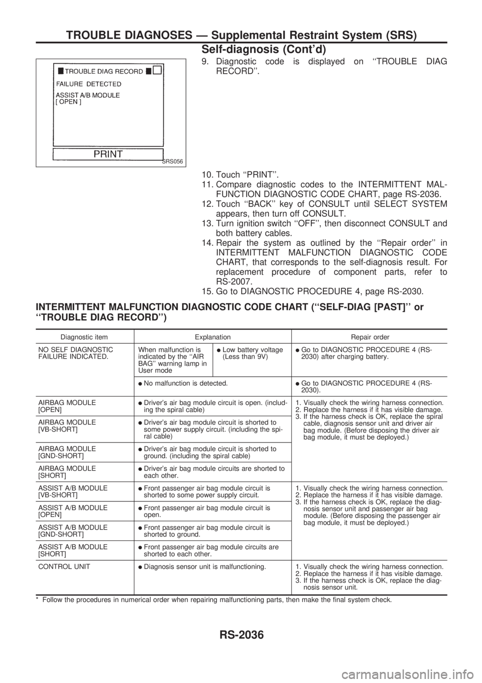
9. Diagnostic code is displayed on ``TROUBLE DIAG
RECORD''.
10. Touch ``PRINT''.
11. Compare diagnostic codes to the INTERMITTENT MAL-
FUNCTION DIAGNOSTIC CODE CHART, page RS-2036.
12. Touch ``BACK'' key of CONSULT until SELECT SYSTEM
appears, then turn off CONSULT.
13. Turn ignition switch ``OFF'', then disconnect CONSULT and
both battery cables.
14. Repair the system as outlined by the ``Repair order'' in
INTERMITTENT MALFUNCTION DIAGNOSTIC CODE
CHART, that corresponds to the self-diagnosis result. For
replacement procedure of component parts, refer to
RS-2007.
15. Go to DIAGNOSTIC PROCEDURE 4, page RS-2030.
INTERMITTENT MALFUNCTION DIAGNOSTIC CODE CHART (``SELF-DIAG [PAST]'' or
``TROUBLE DIAG RECORD'')
Diagnostic item Explanation Repair order
NO SELF DIAGNOSTIC
FAILURE INDICATED.When malfunction is
indicated by the ``AIR
BAG'' warning lamp in
User mode
lLow battery voltage
(Less than 9V)lGo to DIAGNOSTIC PROCEDURE 4 (RS-
2030) after charging battery.
lNo malfunction is detected.lGo to DIAGNOSTIC PROCEDURE 4 (RS-
2030).
AIRBAG MODULE
[OPEN]
lDriver's air bag module circuit is open. (includ-
ing the spiral cable)1. Visually check the wiring harness connection.
2. Replace the harness if it has visible damage.
3. If the harness check is OK, replace the spiral
cable, diagnosis sensor unit and driver air
bag module. (Before disposing the driver air
bag module, it must be deployed.) AIRBAG MODULE
[VB-SHORT]
lDriver's air bag module circuit is shorted to
some power supply circuit. (including the spi-
ral cable)
AIRBAG MODULE
[GND-SHORT]
lDriver's air bag module circuit is shorted to
ground. (including the spiral cable)
AIRBAG MODULE
[SHORT]
lDriver's air bag module circuits are shorted to
each other.
ASSIST A/B MODULE
[VB-SHORT]
lFront passenger air bag module circuit is
shorted to some power supply circuit.1. Visually check the wiring harness connection.
2. Replace the harness if it has visible damage.
3. If the harness check is OK, replace the diag-
nosis sensor unit and passenger air bag
module. (Before disposing the passenger air
bag module, it must be deployed.) ASSIST A/B MODULE
[OPEN]
lFront passenger air bag module circuit is
open.
ASSIST A/B MODULE
[GND-SHORT]
lFront passenger air bag module circuit is
shorted to ground.
ASSIST A/B MODULE
[SHORT]
lFront passenger air bag module circuits are
shorted to each other.
CONTROL UNIT
lDiagnosis sensor unit is malfunctioning. 1. Visually check the wiring harness connection.
2. Replace the harness if it has visible damage.
3. If the harness check is OK, replace the diag-
nosis sensor unit.
* Follow the procedures in numerical order when repairing malfunctioning parts, then make the final system check.
SRS056
TROUBLE DIAGNOSES Ð Supplemental Restraint System (SRS)
Self-diagnosis (Cont'd)
RS-2036
Page 659 of 666
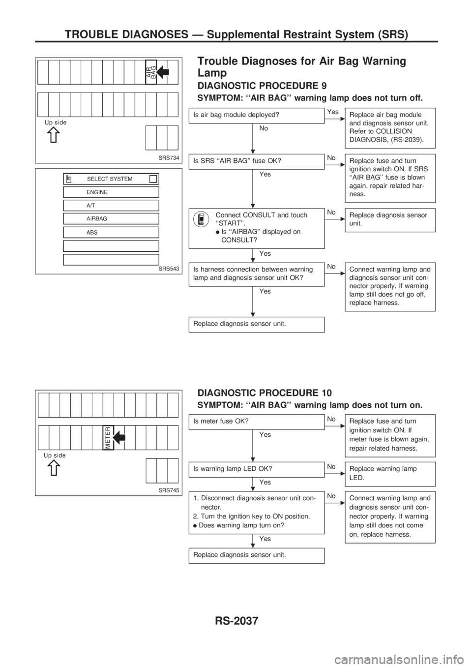
Trouble Diagnoses for Air Bag Warning
Lamp
DIAGNOSTIC PROCEDURE 9
SYMPTOM: ``AIR BAG'' warning lamp does not turn off.
Is air bag module deployed?
No
cYes
Replace air bag module
and diagnosis sensor unit.
Refer to COLLISION
DIAGNOSIS, (RS-2039).
Is SRS ``AIR BAG'' fuse OK?
Yes
cNo
Replace fuse and turn
ignition switch ON. If SRS
``AIR BAG'' fuse is blown
again, repair related har-
ness.
Connect CONSULT and touch
``START''.
lIs ``AIRBAG'' displayed on
CONSULT?
Yes
cNo
Replace diagnosis sensor
unit.
Is harness connection between warning
lamp and diagnosis sensor unit OK?
Yes
cNo
Connect warning lamp and
diagnosis sensor unit con-
nector properly. If warning
lamp still does not go off,
replace harness.
Replace diagnosis sensor unit.
DIAGNOSTIC PROCEDURE 10
SYMPTOM: ``AIR BAG'' warning lamp does not turn on.
Is meter fuse OK?
Yes
cNo
Replace fuse and turn
ignition switch ON. If
meter fuse is blown again,
repair related harness.
Is warning lamp LED OK?
Yes
cNo
Replace warning lamp
LED.
1. Disconnect diagnosis sensor unit con-
nector.
2. Turn the ignition key to ON position.
lDoes warning lamp turn on?
Yes
cNo
Connect warning lamp and
diagnosis sensor unit con-
nector properly. If warning
lamp still does not come
on, replace harness.
Replace diagnosis sensor unit.
SRS734
SRS543
SRS745
.
.
.
.
.
.
.
TROUBLE DIAGNOSES Ð Supplemental Restraint System (SRS)
RS-2037