1999 NISSAN PICK-UP wheel bolts
[x] Cancel search: wheel boltsPage 37 of 666
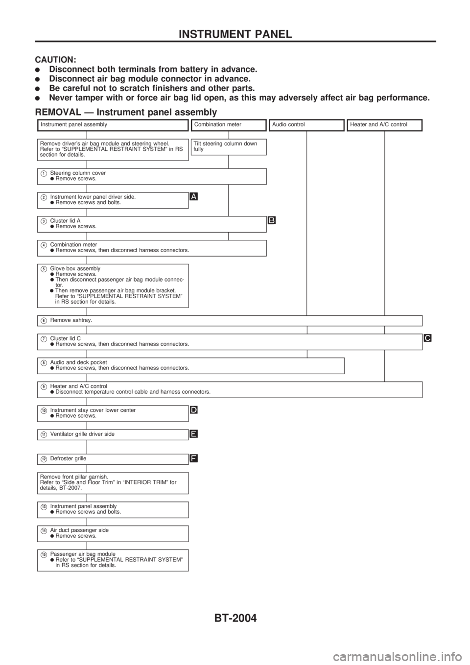
CAUTION:
lDisconnect both terminals from battery in advance.
lDisconnect air bag module connector in advance.
lBe careful not to scratch finishers and other parts.
lNever tamper with or force air bag lid open, as this may adversely affect air bag performance.
REMOVAL Ð Instrument panel assembly
Instrument panel assemblyCombination meterAudio controlHeater and A/C control
Remove driver's air bag module and steering wheel.
Refer to ªSUPPLEMENTAL RESTRAINT SYSTEMº in RS
section for details.Tilt steering column down
fully
V1Steering column coverlRemove screws.
V2Instrument lower panel driver side.lRemove screws and bolts.
V3Cluster lid AlRemove screws.
V4Combination meterlRemove screws, then disconnect harness connectors.
V5Glove box assemblylRemove screws.lThen disconnect passenger air bag module connec-
tor.
lThen remove passenger air bag module bracket.
Refer to ªSUPPLEMENTAL RESTRAINT SYSTEMº
in RS section for details.
V6Remove ashtray.
V7Cluster lid ClRemove screws, then disconnect harness connectors.
V8Audio and deck pocketlRemove screws, then disconnect harness connectors.
V9Heater and A/C controllDisconnect temperature control cable and harness connectors.
V10Instrument stay cover lower centerlRemove screws.
V11Ventilator grille driver side
V12Defroster grille
Remove front pillar garnish.
Refer to ªSide and Floor Trimº in ªINTERIOR TRIMº for
details, BT-2007.
V13Instrument panel assemblylRemove screws and bolts.
V14Air duct passenger sidelRemove screws.
V15Passenger air bag modulelRefer to ªSUPPLEMENTAL RESTRAINT SYSTEMº
in RS section for details.
INSTRUMENT PANEL
BT-2004
Page 425 of 666
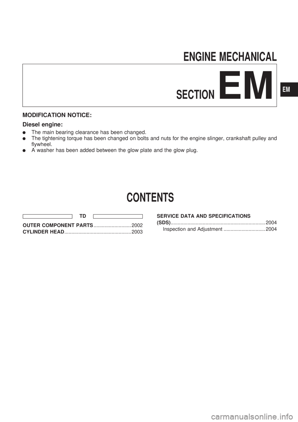
ENGINE MECHANICAL
SECTION
EM
MODIFICATION NOTICE:
Diesel engine:
lThe main bearing clearance has been changed.
lThe tightening torque has been changed on bolts and nuts for the engine slinger, crankshaft pulley and
flywheel.
lA washer has been added between the glow plate and the glow plug.
CONTENTS
TD
OUTER COMPONENT PARTS........................... 2002
CYLINDER HEAD................................................ 2003SERVICE DATA AND SPECIFICATIONS
(SDS).................................................................... 2004
Inspection and Adjustment .............................. 2004
EM
Page 464 of 666
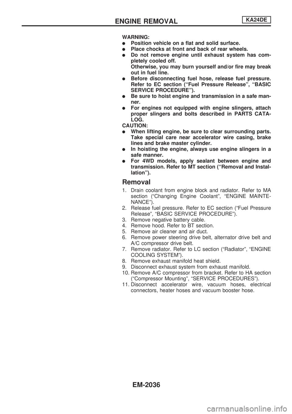
WARNING:
lPosition vehicle on a flat and solid surface.
lPlace chocks at front and back of rear wheels.
lDo not remove engine until exhaust system has com-
pletely cooled off.
Otherwise, you may burn yourself and/or fire may break
out in fuel line.
lBefore disconnecting fuel hose, release fuel pressure.
Refer to EC section (ªFuel Pressure Releaseº, ªBASIC
SERVICE PROCEDUREº).
lBe sure to hoist engine and transmission in a safe man-
ner.
lFor engines not equipped with engine slingers, attach
proper slingers and bolts described in PARTS CATA-
LOG.
CAUTION:
lWhen lifting engine, be sure to clear surrounding parts.
Take special care near accelerator wire casing, brake
lines and brake master cylinder.
lIn hoisting the engine, always use engine slingers in a
safe manner.
lFor 4WD models, apply sealant between engine and
transmission. Refer to MT section (ªRemoval and Instal-
lationº).
Removal
1. Drain coolant from engine block and radiator. Refer to MA
section (ªChanging Engine Coolantº, ªENGINE MAINTE-
NANCEº).
2. Release fuel pressure. Refer to EC section (ªFuel Pressure
Releaseº, ªBASIC SERVICE PROCEDUREº).
3. Remove negative battery cable.
4. Remove hood. Refer to BT section.
5. Remove air cleaner and air duct.
6. Remove power steering drive belt, alternator drive belt and
A/C compressor drive belt.
7. Remove radiator. Refer to LC section (ªRadiatorº, ªENGINE
COOLING SYSTEMº).
8. Remove exhaust manifold heat shield.
9. Disconnect exhaust system from exhaust manifold.
10. Remove A/C compressor from bracket. Refer to HA section
(ªCompressor Mountingº, ªSERVICE PROCEDURESº).
11. Disconnect accelerator wire, vacuum hoses, electrical
connectors, heater hoses and vacuum booster hose.
ENGINE REMOVALKA24DE
EM-2036
Page 467 of 666
CAUTION:
lWhen installing sliding parts (bearings, pistons, etc.),
lubricate contacting surfaces with new engine oil.
lPlace removed parts such as bearings and bearing caps
in their proper order and direction.
lWhen installing connecting rod nuts and main bearing
cap bolts, apply new engine oil to threads and seating
surfaces.
lDo not allow any magnetic materials to contact the ring
gear teeth of flywheel or drive plate.
Disassembly
PISTON AND CRANKSHAFT
1. Place engine on a work stand.
2. Drain coolant and oil.
3. Remove oil pan.
4. Remove timing chain. Refer to ªRemovalº in ªTIMING
CHAINº (EM-2015).
5. Remove water pump.
6. Remove cylinder head.
7. Remove pistons with connecting rods.
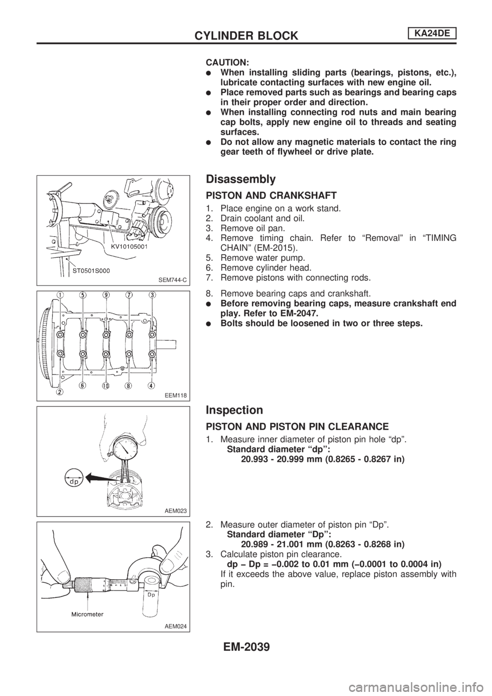
8. Remove bearing caps and crankshaft.
lBefore removing bearing caps, measure crankshaft end
play. Refer to EM-2047.
lBolts should be loosened in two or three steps.
Inspection
PISTON AND PISTON PIN CLEARANCE
1. Measure inner diameter of piston pin hole ªdpº.
Standard diameter ªdpº:
20.993 - 20.999 mm (0.8265 - 0.8267 in)
2. Measure outer diameter of piston pin ªDpº.
Standard diameter ªDpº:
20.989 - 21.001 mm (0.8263 - 0.8268 in)
3. Calculate piston pin clearance.
dp þ Dp = þ0.002 to 0.01 mm (þ0.0001 to 0.0004 in)
If it exceeds the above value, replace piston assembly with
pin.
SEM744-C
EEM118
AEM023
AEM024
CYLINDER BLOCKKA24DE
EM-2039
Page 626 of 666
Precautions for SRS ``AIR BAG'' and ``SEAT
BELT PRE-TENSIONER'' Service
lDo not use electrical test equipment to check SRS circuits unless instructed to in this Service Manual.
lBefore servicing the SRS, turn ignition switch ``OFF'', disconnect both battery cables and wait at least
3 minutes.
For approximately 3 minutes after the cables are removed, it is still possible for the air bag to deploy.
Therefore, do not work on any SRS connectors or wires until at least 3 minutes have passed.
lDiagnosis sensor unit must always be installed with their arrow marks ``S'' pointing towards the front of
the vehicle for proper operation. Also check diagnosis sensor unit for cracks, deformities or rust before
installation and replace as required.
lThe spiral cable must be aligned with the neutral position since its rotations are limited. Do not attempt
to turn steering wheel or column after removal of steering gear.
lHandle air bag module carefully. Always place driver and passenger air bag modules with the pad side
facing upward.
lConduct self-diagnosis to check entire SRS for proper function after replacing any components.
lAfter air bag inflates, the front instrument panel assembly should be replaced if damaged.
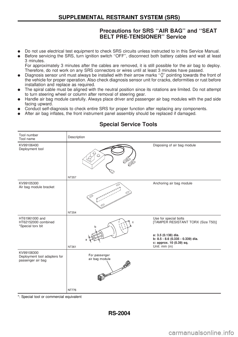
Special Service Tools
Tool number
Tool nameDescription
KV99106400
Deployment tool
NT357
Disposing of air bag module
KV99105300
Air bag module bracket
NT354
Anchoring air bag module
HT61961000 and
HT62152000 combined
*Special torx bit
NT361
Use for special bolts
[TAMPER RESISTANT TORX (Size T50)]
a: 3.5 (0.138) dia.
b: 8.5 - 8.6 (0.335 - 0.339) dia.
c: approx. 10 (0.39) sq.
Unit: mm (in)
KV99108300
Deployment tool adapters for
passenger air bag
NT776
*: Special tool or commercial equivalent
SUPPLEMENTAL RESTRAINT SYSTEM (SRS)
RS-2004
Page 629 of 666
lRemove air bag module from steering wheel, instrument
panel or seat back. Check harness cover and connectors for
damage, terminals for deformities, and harness for binding.
lInstall driver air bag module to steering wheel to check fit or
alignment with the wheel.
lCheck steering wheel for excessive free play.
lInstall passenger air bag module to instrument panel to
check fit or alignment with the instrument panel.
(3) Spiral cable
lCheck spiral cable for dents, cracks, or deformities.
lCheck connectors and protective tape for damage.
lCheck steering wheel for noise, binding or heavy operation.
(4) Main harness and air bag harness
lCheck connectors for poor connections, damage, and termi-
nals for deformities.
lCheck harnesses for binding, chafing or cut.
CAUTION:
Replace previously used special bolts and ground bolt with
new ones.
Removal and Installation Ð Diagnosis
Sensor Unit
CAUTION:
lBefore servicing SRS, turn the ignition switch off, disconnect both battery cables and wait at least
3 minutes.
lDo not use old special bolts and nuts coated with bonding agent after removal; replace with new
ones.
lCheck diagnosis sensor unit for proper installation.
lCheck diagnosis sensor unit to ensure it is free of deformities, dents, cracks or rust. If it shows
any visible signs of damage, replace it with a new one.
lCheck diagnosis sensor unit brackets to ensure they are free of deformities and rust.
lAfter replacement of diagnosis sensor unit, check SRS function and perform self-diagnosis for
SRS. Refer to ``Self-diagnosis'' for details. (RS-2025)
lDo not attempt to disassemble diagnosis sensor unit.
lReplace diagnosis sensor unit and if it has been dropped or sustained an impact.
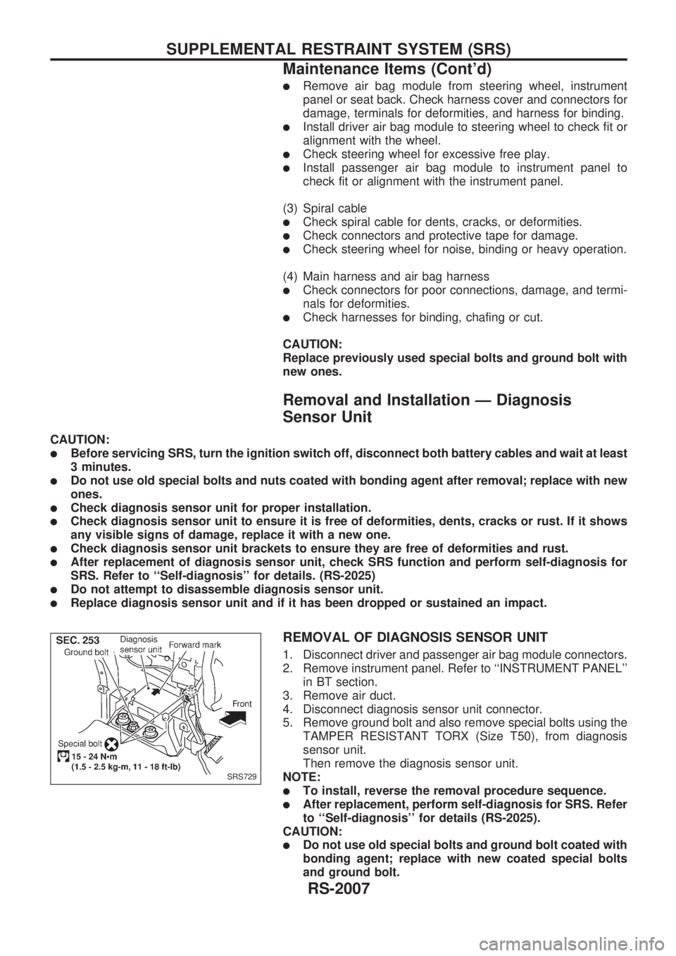
REMOVAL OF DIAGNOSIS SENSOR UNIT
1. Disconnect driver and passenger air bag module connectors.
2. Remove instrument panel. Refer to ``INSTRUMENT PANEL''
in BT section.
3. Remove air duct.
4. Disconnect diagnosis sensor unit connector.
5. Remove ground bolt and also remove special bolts using the
TAMPER RESISTANT TORX (Size T50), from diagnosis
sensor unit.
Then remove the diagnosis sensor unit.
NOTE:
lTo install, reverse the removal procedure sequence.
lAfter replacement, perform self-diagnosis for SRS. Refer
to ``Self-diagnosis'' for details (RS-2025).
CAUTION:
lDo not use old special bolts and ground bolt coated with
bonding agent; replace with new coated special bolts
and ground bolt.
SRS729
SUPPLEMENTAL RESTRAINT SYSTEM (SRS)
Maintenance Items (Cont'd)
RS-2007
Page 630 of 666
Removal Ð Driver Air Bag Module and Spiral
Cable
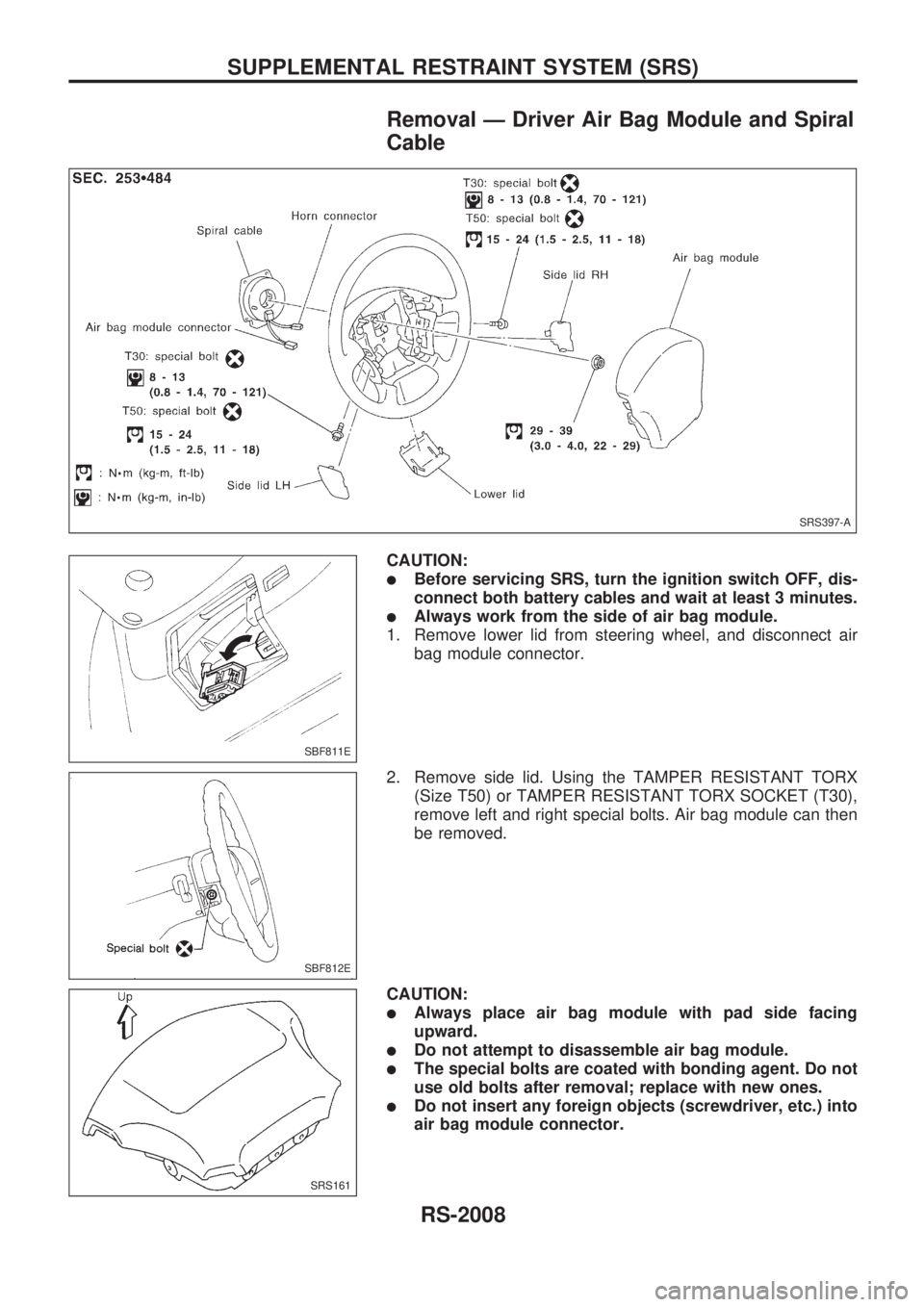
CAUTION:
lBefore servicing SRS, turn the ignition switch OFF, dis-
connect both battery cables and wait at least 3 minutes.
lAlways work from the side of air bag module.
1. Remove lower lid from steering wheel, and disconnect air
bag module connector.
2. Remove side lid. Using the TAMPER RESISTANT TORX
(Size T50) or TAMPER RESISTANT TORX SOCKET (T30),
remove left and right special bolts. Air bag module can then
be removed.
CAUTION:
lAlways place air bag module with pad side facing
upward.
lDo not attempt to disassemble air bag module.
lThe special bolts are coated with bonding agent. Do not
use old bolts after removal; replace with new ones.
lDo not insert any foreign objects (screwdriver, etc.) into
air bag module connector.
SRS397-A
SBF811E
SBF812E
SRS161
SUPPLEMENTAL RESTRAINT SYSTEM (SRS)
RS-2008
Page 632 of 666
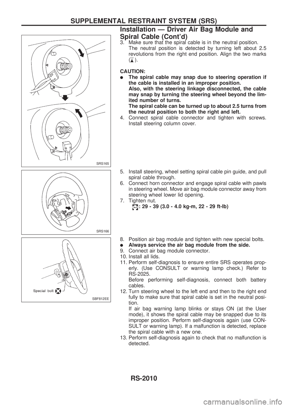
3. Make sure that the spiral cable is in the neutral position.
The neutral position is detected by turning left about 2.5
revolutions from the right end position. Align the two marks
(
,
s).
CAUTION:
lThe spiral cable may snap due to steering operation if
the cable is installed in an improper position.
Also, with the steering linkage disconnected, the cable
may snap by turning the steering wheel beyond the lim-
ited number of turns.
The spiral cable can be turned up to about 2.5 turns from
the neutral position to both the right and left.
4. Connect spiral cable connector and tighten with screws.
Install steering column cover.
5. Install steering, wheel setting spiral cable pin guide, and pull
spiral cable through.
6. Connect horn connector and engage spiral cable with pawls
in steering wheel. Move air bag module connector away from
steering wheel lower lid opening.
7. Tighten nut.
: 29 - 39 (3.0 - 4.0 kg-m, 22 - 29 ft-lb)
8. Position air bag module and tighten with new special bolts.
lAlways service the air bag module from the side.
9. Connect air bag module connector.
10. Install all lids.
11. Perform self-diagnosis to ensure entire SRS operates prop-
erly. (Use CONSULT or warning lamp check.) Refer to
RS-2025.
Before performing self-diagnosis, connect both battery
cables.
12. Turn steering wheel to the left end and then to the right end
fully to make sure that spiral cable is set in the neutral posi-
tion.
If air bag warning lamp blinks or stays ON (at the User
mode), it shows the spiral cable may be snapped due to its
improper position. Perform self-diagnosis again (use CON-
SULT or warning lamp). If a malfunction is detected, replace
the spiral cable with a new one.
13. Perform self-diagnosis again to check that no malfunction is
detected.
SRS165
SRS166
SBF812EE
SUPPLEMENTAL RESTRAINT SYSTEM (SRS)
Installation Ð Driver Air Bag Module and
Spiral Cable (Cont'd)
RS-2010