1999 NISSAN PICK-UP belt
[x] Cancel search: beltPage 34 of 666
BODY&TRIM
SECTION
BT
MODIFICATION NOTICE:
lThe instrument panel has been changed.
lThe body side trim has been changed.
lThe headlining has been changed.
lA jump seat has been added.
lAn auto reverse function has been added to the driver's door window.
CONTENTS
PRECAUTIONS ................................................... 2002
Supplemental Restraint System (SRS) ``AIR
BAG'' and ``SEAT BELT PRE-TENSIONER'' .. 2002
DOOR ................................................................... 2003
Front Door Limit Switch Reset (Driver side
only) ................................................................. 2003 INSTRUMENT PANEL
......................................... 2004
INTERIOR TRIM .................................................. 2007
Side and Floor Trim ......................................... 2007
Roof Trim ......................................................... 2010
SEAT .................................................................... 2012
Jump Seat - King Cab Model .......................... 2012
BT
Page 35 of 666
Supplemental Restraint System (SRS) ``AIR
BAG'' and ``SEAT BELT PRE-TENSIONER''
The Supplemental Restraint System such as ªAIR BAGº and ªSEAT BELT PRE-TENSIONERº used along
with a seat belt, helps to reduce the risk or severity of injury to the driver and front passenger in a frontal
collision. The SRS system composition which is available to NISSAN MODEL D22 is as follows (The com-
position varies according to the destination and optional equipment.):
Driver air bag module (located in the center of the steering wheel), front passenger air bag module (located
on the instrument panel on passenger side), seat belt pre-tensioner, a diagnosis sensor unit, warning lamp,
wiring harness and spiral cable.
Information necessary to service the system safely is included in theRS sectionof this Service Manual.
WARNING:
lTo avoid rendering the SRS inoperative, which could increase the risk of personal injury or death
in the event of a collision which would result in air bag inflation, all maintenance must be per-
formed by an authorized NISSAN dealer.
lImproper maintenance, including incorrect removal and installation of the SRS, can lead to per-
sonal injury caused by unintentional activation of the system. For removal of Spiral Cable and
Air Bag Module, see the RS section.
lDo not use electrical test equipment on any circuit related to the SRS unless instructed to in this
Service Manual. Spiral Cable and wiring harnesses (except ªSEAT BELT PRE-TENSIONERº) cov-
ered with yellow insulation either just before the harness connectors or for the complete harness
are related to the SRS.
PRECAUTIONS
BT-2002
Page 40 of 666
Side and Floor Trim
CAUTION:
Wrap the tip of flat-bladed screwdriver with a cloth when removing metal clips from garnishes.
REMOVAL Ð Body side trim
V1Remove front and rear seats. Refer to ªSEATº for details, in BT section of Service Manual Pub. No.
SM8E-0D22E0E.
V2Remove front and rear seat belts. Refer to ªSEAT BELTSº in RS section details.
V3Remove front and rear kicking plate.
V4Remove dash side lower finishers.
V5Remove front and rear body side welts.
V6Remove front pillar garnishes.
V7Remove center pillar lower garnishes.
V8Remove center pillar upper garnishes.
V9Remove lock pillar garnishes.
INTERIOR TRIM
BT-2007
Page 43 of 666
Roof Trim
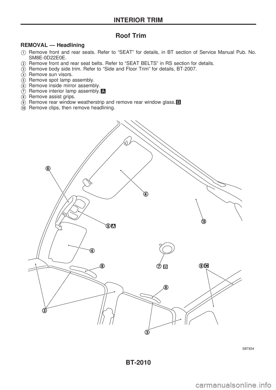
REMOVAL Ð Headlining
V1Remove front and rear seats. Refer to ªSEATº for details, in BT section of Service Manual Pub. No.
SM8E-0D22E0E.
V2Remove front and rear seat belts. Refer to ªSEAT BELTSº in RS section for details.
V3Remove body side trim. Refer to ªSide and Floor Trimº for details, BT-2007.
V4Remove sun visors.
V5Remove spot lamp assembly.
V6Remove inside mirror assembly.
V7Remove interior lamp assembly.
V8Remove assist grips.
V9Remove rear window weatherstrip and remove rear window glass.
V10Remove clips, then remove headlining.
SBT834
INTERIOR TRIM
BT-2010
Page 46 of 666
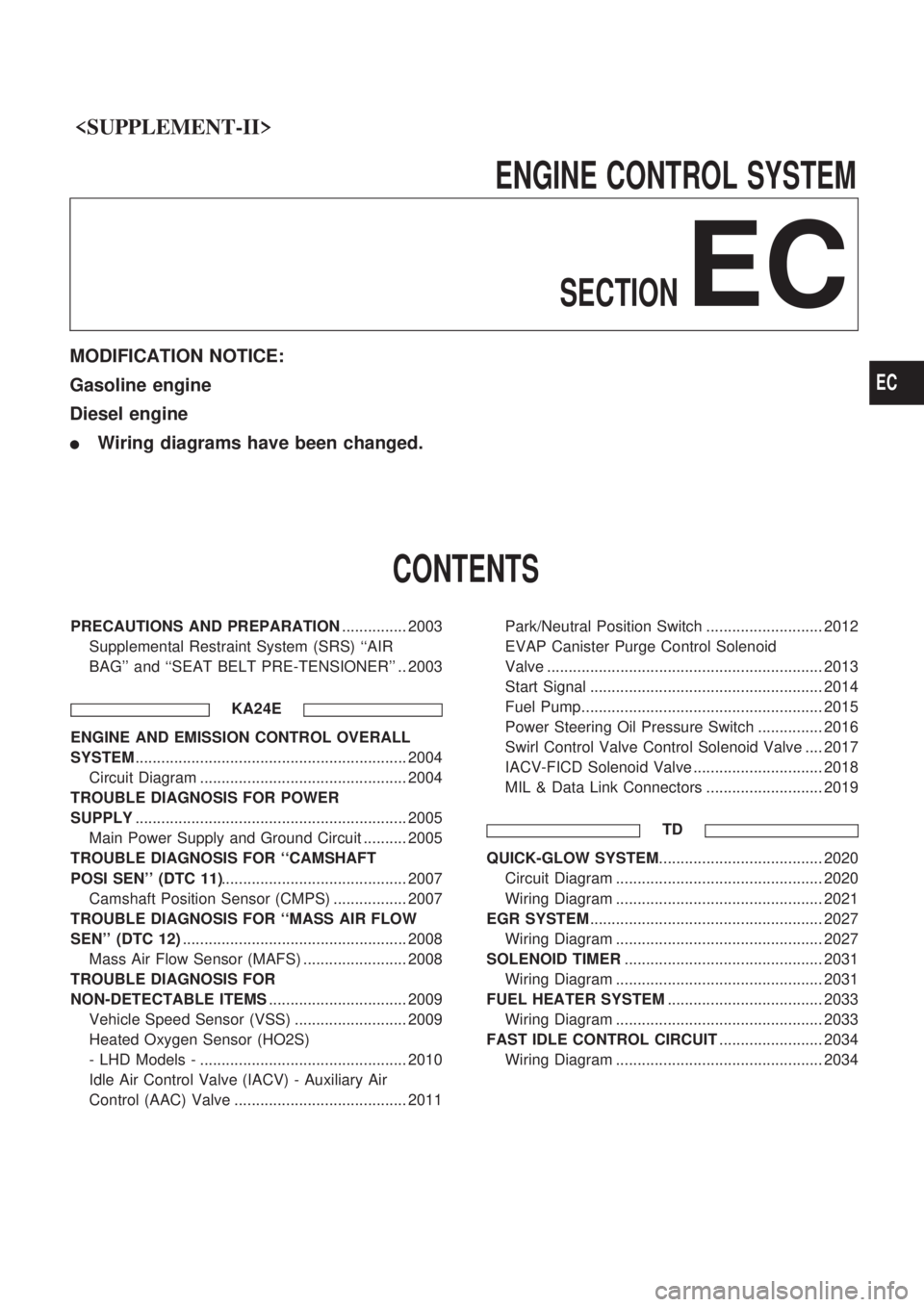
ENGINECONTROLSYSTEM
SECTION
EC
MODIFICATION NOTICE:
Gasoline engine
Diesel engine
lWiring diagrams have been changed.
CONTENTS
PRECAUTIONS AND PREPARATION ............... 2003
Supplemental Restraint System (SRS) ``AIR
BAG'' and ``SEAT BELT PRE-TENSIONER'' .. 2003
KA24E
ENGINE AND EMISSION CONTROL OVERALL
SYSTEM............................................................... 2004
Circuit Diagram ................................................ 2004
TROUBLE DIAGNOSIS FOR POWER
SUPPLY ............................................................... 2005
Main Power Supply and Ground Circuit .......... 2005
TROUBLE DIAGNOSIS FOR ``CAMSHAFT
POSI SEN'' (DTC 11) ........................................... 2007
Camshaft Position Sensor (CMPS) ................. 2007
TROUBLE DIAGNOSIS FOR ``MASS AIR FLOW
SEN'' (DTC 12) .................................................... 2008
Mass Air Flow Sensor (MAFS) ........................ 2008
TROUBLE DIAGNOSIS FOR
NON-DETECTABLE ITEMS ................................ 2009
Vehicle Speed Sensor (VSS) .......................... 2009
Heated Oxygen Sensor (HO2S)
- LHD Models - ................................................ 2010
Idle Air Control Valve (IACV) - Auxiliary Air
Control (AAC) Valve ........................................ 2011 Park/Neutral Position Switch ........................... 2012
EVAP Canister Purge Control Solenoid
Valve ................................................................ 2013
Start Signal ...................................................... 2014
Fuel Pump........................................................ 2015
Power Steering Oil Pressure Switch ............... 2016
Swirl Control Valve Control Solenoid Valve .... 2017
IACV-FICD Solenoid Valve .............................. 2018
MIL & Data Link Connectors ........................... 2019
TD
QUICK-GLOW SYSTEM ...................................... 2020
Circuit Diagram ................................................ 2020
Wiring Diagram ................................................ 2021
EGR SYSTEM ...................................................... 2027
Wiring Diagram ................................................ 2027
SOLENOID TIMER .............................................. 2031
Wiring Diagram ................................................ 2031
FUEL HEATER SYSTEM .................................... 2033
Wiring Diagram ................................................ 2033
FAST IDLE CONTROL CIRCUIT ........................ 2034
Wiring Diagram ................................................ 2034
EC
Page 48 of 666
Supplemental Restraint System (SRS) ªAIR
BAGº and ªSEAT BELT PRE-TENSIONERº
The Supplemental Restraint System such as ªAIR BAGº and ªSEAT BELT PRE-TENSIONERº used along
with a seat belt, helps to reduce the risk or severity of injury to the driver and front passenger in a frontal
collision. The SRS system composition which is available to NISSAN MODEL D22 is as follows (The com-
position varies according to the destination and optional equipment.):
Driver air bag module (located in the center of the steering wheel), front passenger air bag module (located
on the instrument panel on passenger side), seat belt pre-tensioner, a diagnosis sensor unit, warning lamp,
wiring harness and spiral cable.
Information necessary to service the system safely is included in theRS sectionof this Service Manual.
WARNING:
lTo avoid rendering the SRS inoperative, which could increase the risk of personal injury or death
in the event of a collision which would result in air bag inflation, all maintenance must be per-
formed by an authorized NISSAN dealer.
lImproper maintenance, including incorrect removal and installation of the SRS, can lead to per-
sonal injury caused by unintentional activation of the system. For removal of Spiral Cable and
Air Bag Module, see the RS section.
lDo not use electrical test equipment on any circuit related to the SRS unless instructed to in this
Service Manual. Spiral Cable and wiring harnesses (except ªSEAT BELT PRE-TENSIONERº) cov-
ered with yellow insulation either just before the harness connectors or for the complete harness
are related to the SRS.
PRECAUTIONS AND PREPARATION
EC-2003
Page 80 of 666
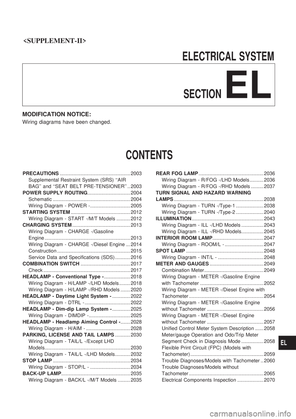
ELECTRICALSYSTEM
SECTION
EL
MODIFICATION NOTICE:
Wiring diagrams have been changed.
CONTENTS
PRECAUTIONS ................................................... 2003
Supplemental Restraint System (SRS) ``AIR
BAG'' and ``SEAT BELT PRE-TENSIONER'' .. 2003
POWER SUPPLY ROUTING ............................... 2004
Schematic ........................................................ 2004
Wiring Diagram - POWER -............................. 2005
STARTING SYSTEM ........................................... 2012
Wiring Diagram - START -/M/T Models .......... 2012
CHARGING SYSTEM .......................................... 2013
Wiring Diagram - CHARGE -/Gasoline
Engine .............................................................. 2013
Wiring Diagram - CHARGE -/Diesel Engine ... 2014
Construction ..................................................... 2015
Service Data and Specifications (SDS) ........... 2016
COMBINATION SWITCH .................................... 2017
Check ............................................................... 2017
HEADLAMP - Conventional Type - ................... 2018
Wiring Diagram - H/LAMP -/LHD Models ........ 2018
Wiring Diagram - H/LAMP -/RHD Models ....... 2020
HEADLAMP - Daytime Light System - ............. 2022
Wiring Diagram - DTRL - ................................. 2022
HEADLAMP - Dim-dip Lamp System - ............. 2025
Wiring Diagram - DIMDIP -.............................. 2025
HEADLAMP - Headlamp Aiming Control - ....... 2028
Wiring Diagram - H/AIM - ................................ 2028
PARKING, LICENSE AND TAIL LAMPS ........... 2030
Wiring Diagram - TAIL/L -/Except LHD
Models.............................................................. 2030
Wiring Diagram - TAIL/L -/LHD Models........... 2032
STOP LAMP ........................................................ 2034
Wiring Diagram - STOP/L - ............................. 2034
BACK-UP LAMP .................................................. 2035
Wiring Diagram - BACK/L -/M/T Models ......... 2035 REAR FOG LAMP
............................................... 2036
Wiring Diagram - R/FOG -/LHD Models .......... 2036
Wiring Diagram - R/FOG -/RHD Models ......... 2037
TURN SIGNAL AND HAZARD WARNING
LAMPS ................................................................. 2038
Wiring Diagram - TURN -/Type-1 .................... 2038
Wiring Diagram - TURN -/Type-2 .................... 2040
ILLUMINATION .................................................... 2043
Wiring Diagram - ILL -/LHD Models ................ 2043
Wiring Diagram - ILL -/RHD Models................ 2045
INTERIOR ROOM LAMP ..................................... 2047
Wiring Diagram - ROOM/L - ............................ 2047
SPOT LAMP ........................................................ 2048
Wiring Diagram - INT/L - ................................. 2048
METER AND GAUGES ....................................... 2049
Combination Meter........................................... 2049
Wiring Diagram - METER -/Gasoline Engine
with Tachometer .............................................. 2052
Wiring Diagram - METER -/Diesel Engine with
Tachometer ...................................................... 2054
Wiring Diagram - METER -/Gasoline Engine
without Tachometer ......................................... 2056
Wiring Diagram - METER -/Diesel Engine
without Tachometer ......................................... 2057
Unified Control Meter System Description ...... 2058
Meter/gauge Operation and Odo/Trip Meter
Segment Check in Diagnosis Mode ................ 2058
Flexible Print Circuit (FPC) (Models with
Tachometer) ..................................................... 2059
Trouble Diagnoses/Models with Tachometer .. 2060
Trouble Diagnoses/Models without
Tachometer ...................................................... 2065
Electrical Components Inspection ................... 2070
EL
Page 82 of 666
Supplemental Restraint System (SRS) ``AIR
BAG'' and ``SEAT BELT PRE-TENSIONER''
The Supplemental Restraint System such as ``AIR BAG'' and ``SEAT BELT PRE-TENSIONER'' used along
with a seat belt, helps to reduce the risk or severity of injury to the driver and front passenger in a frontal
collision. The SRS system composition which is available to NISSAN MODEL D22 is as follows (The com-
position varies according to the destination and optional equipment.):
Driver air bag module (located in the center of the steering wheel), front passenger air bag module (located
on the instrument panel on passenger side), seat belt pre-tensioner, a diagnosis sensor unit, warning lamp,
wiring harness and spiral cable.
Information necessary to service the system safely is included in theRS sectionof this Service Manual.
WARNING:
lTo avoid rendering the SRS inoperative, which could increase the risk of personal injury or death
in the event of a collision which would result in air bag inflation, all maintenance must be per-
formed by an authorized NISSAN dealer.
lImproper maintenance, including incorrect removal and installation of the SRS, can lead to per-
sonal injury caused by unintentional activation of the system. For removal of Spiral Cable and
Air Bag Module, see the RS section.
lDo not use electrical test equipment on any circuit related to the SRS unless instructed to in this
Service Manual. Spiral Cable and wiring harnesses (except ``SEAT BELT PRE-TENSIONER'')
covered with yellow insulation either just before the harness connectors or for the complete har-
ness are related to the SRS.
PRECAUTIONS
EL-2003