1999 NISSAN PICK-UP belt
[x] Cancel search: beltPage 252 of 666
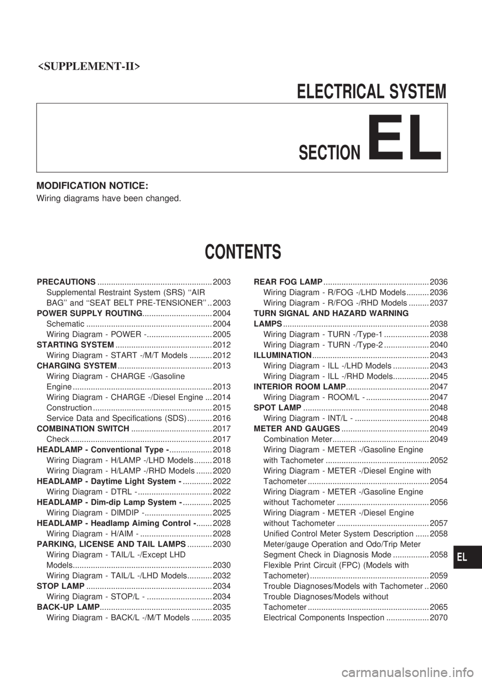
ELECTRICALSYSTEM
SECTION
EL
MODIFICATION NOTICE:
Wiring diagrams have been changed.
CONTENTS
PRECAUTIONS ................................................... 2003
Supplemental Restraint System (SRS) ``AIR
BAG'' and ``SEAT BELT PRE-TENSIONER'' .. 2003
POWER SUPPLY ROUTING ............................... 2004
Schematic ........................................................ 2004
Wiring Diagram - POWER -............................. 2005
STARTING SYSTEM ........................................... 2012
Wiring Diagram - START -/M/T Models .......... 2012
CHARGING SYSTEM .......................................... 2013
Wiring Diagram - CHARGE -/Gasoline
Engine .............................................................. 2013
Wiring Diagram - CHARGE -/Diesel Engine ... 2014
Construction ..................................................... 2015
Service Data and Specifications (SDS) ........... 2016
COMBINATION SWITCH .................................... 2017
Check ............................................................... 2017
HEADLAMP - Conventional Type - ................... 2018
Wiring Diagram - H/LAMP -/LHD Models ........ 2018
Wiring Diagram - H/LAMP -/RHD Models ....... 2020
HEADLAMP - Daytime Light System - ............. 2022
Wiring Diagram - DTRL - ................................. 2022
HEADLAMP - Dim-dip Lamp System - ............. 2025
Wiring Diagram - DIMDIP -.............................. 2025
HEADLAMP - Headlamp Aiming Control - ....... 2028
Wiring Diagram - H/AIM - ................................ 2028
PARKING, LICENSE AND TAIL LAMPS ........... 2030
Wiring Diagram - TAIL/L -/Except LHD
Models.............................................................. 2030
Wiring Diagram - TAIL/L -/LHD Models........... 2032
STOP LAMP ........................................................ 2034
Wiring Diagram - STOP/L - ............................. 2034
BACK-UP LAMP .................................................. 2035
Wiring Diagram - BACK/L -/M/T Models ......... 2035 REAR FOG LAMP
............................................... 2036
Wiring Diagram - R/FOG -/LHD Models .......... 2036
Wiring Diagram - R/FOG -/RHD Models ......... 2037
TURN SIGNAL AND HAZARD WARNING
LAMPS ................................................................. 2038
Wiring Diagram - TURN -/Type-1 .................... 2038
Wiring Diagram - TURN -/Type-2 .................... 2040
ILLUMINATION .................................................... 2043
Wiring Diagram - ILL -/LHD Models ................ 2043
Wiring Diagram - ILL -/RHD Models................ 2045
INTERIOR ROOM LAMP ..................................... 2047
Wiring Diagram - ROOM/L - ............................ 2047
SPOT LAMP ........................................................ 2048
Wiring Diagram - INT/L - ................................. 2048
METER AND GAUGES ....................................... 2049
Combination Meter........................................... 2049
Wiring Diagram - METER -/Gasoline Engine
with Tachometer .............................................. 2052
Wiring Diagram - METER -/Diesel Engine with
Tachometer ...................................................... 2054
Wiring Diagram - METER -/Gasoline Engine
without Tachometer ......................................... 2056
Wiring Diagram - METER -/Diesel Engine
without Tachometer ......................................... 2057
Unified Control Meter System Description ...... 2058
Meter/gauge Operation and Odo/Trip Meter
Segment Check in Diagnosis Mode ................ 2058
Flexible Print Circuit (FPC) (Models with
Tachometer) ..................................................... 2059
Trouble Diagnoses/Models with Tachometer .. 2060
Trouble Diagnoses/Models without
Tachometer ...................................................... 2065
Electrical Components Inspection ................... 2070
EL
Page 254 of 666
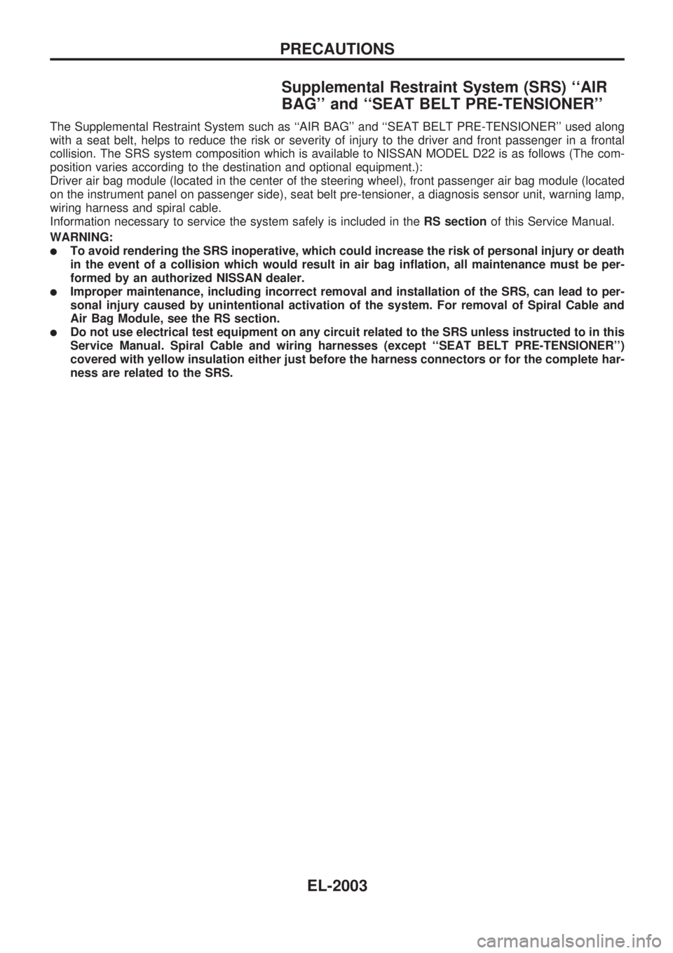
Supplemental Restraint System (SRS) ``AIR
BAG'' and ``SEAT BELT PRE-TENSIONER''
The Supplemental Restraint System such as ``AIR BAG'' and ``SEAT BELT PRE-TENSIONER'' used along
with a seat belt, helps to reduce the risk or severity of injury to the driver and front passenger in a frontal
collision. The SRS system composition which is available to NISSAN MODEL D22 is as follows (The com-
position varies according to the destination and optional equipment.):
Driver air bag module (located in the center of the steering wheel), front passenger air bag module (located
on the instrument panel on passenger side), seat belt pre-tensioner, a diagnosis sensor unit, warning lamp,
wiring harness and spiral cable.
Information necessary to service the system safely is included in theRS sectionof this Service Manual.
WARNING:
lTo avoid rendering the SRS inoperative, which could increase the risk of personal injury or death
in the event of a collision which would result in air bag inflation, all maintenance must be per-
formed by an authorized NISSAN dealer.
lImproper maintenance, including incorrect removal and installation of the SRS, can lead to per-
sonal injury caused by unintentional activation of the system. For removal of Spiral Cable and
Air Bag Module, see the RS section.
lDo not use electrical test equipment on any circuit related to the SRS unless instructed to in this
Service Manual. Spiral Cable and wiring harnesses (except ``SEAT BELT PRE-TENSIONER'')
covered with yellow insulation either just before the harness connectors or for the complete har-
ness are related to the SRS.
PRECAUTIONS
EL-2003
Page 443 of 666
Removal
CAUTION:
lAfter removing the timing chain, do not turn crankshaft
and camshaft separately, or valves will strike piston
heads.
lWhen installing chain tensioners or other sliding parts,
lubricate contacting surfaces with new engine oil.
lApply new engine oil to bolt threads and seat surfaces
when installing camshaft sprockets and crankshaft pul-
ley.
lDo not spill engine coolant on drive belts.
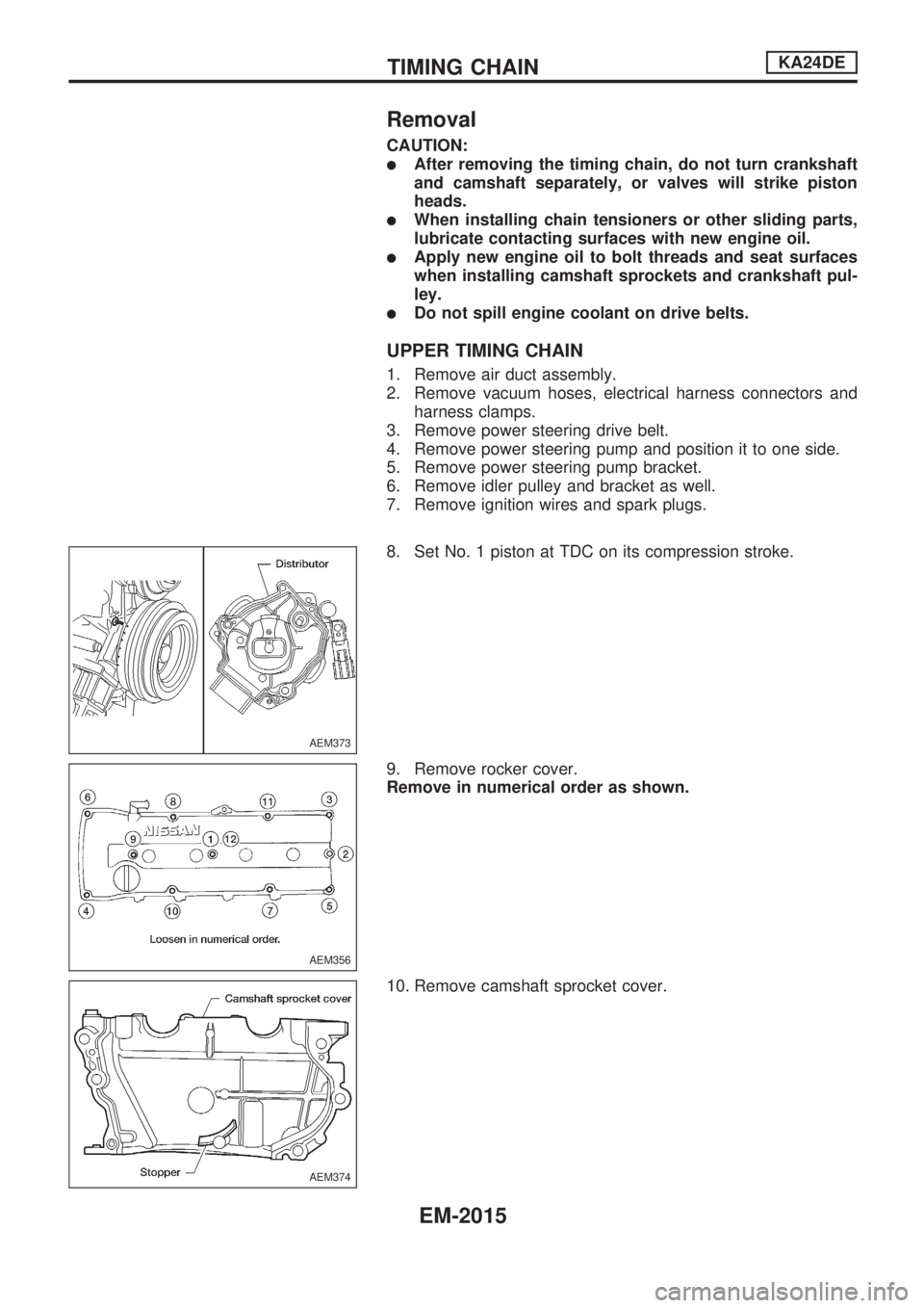
UPPER TIMING CHAIN
1. Remove air duct assembly.
2. Remove vacuum hoses, electrical harness connectors and
harness clamps.
3. Remove power steering drive belt.
4. Remove power steering pump and position it to one side.
5. Remove power steering pump bracket.
6. Remove idler pulley and bracket as well.
7. Remove ignition wires and spark plugs.
8. Set No. 1 piston at TDC on its compression stroke.
9. Remove rocker cover.
Remove in numerical order as shown.
10. Remove camshaft sprocket cover.
AEM373
AEM356
AEM374
TIMING CHAINKA24DE
EM-2015
Page 444 of 666
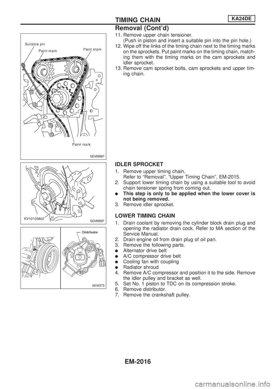
11. Remove upper chain tensioner.
(Push in piston and insert a suitable pin into the pin hole.)
12. Wipe off the links of the timing chain next to the timing marks
on the sprockets. Put paint marks on the timing chain, match-
ing them with the timing marks on the cam sprockets and
idler sprocket.
13. Remove cam sprocket bolts, cam sprockets and upper tim-
ing chain.
IDLER SPROCKET
1. Remove upper timing chain.
Refer to ªRemovalº, ªUpper Timing Chainº, EM-2015.
2. Support lower timing chain by using a suitable tool to avoid
chain tensioner spring from coming out.
lThis step is only to be applied when the lower cover is
not being removed.
3. Remove idler sprocket.
LOWER TIMING CHAIN
1. Drain coolant by removing the cylinder block drain plug and
opening the radiator drain cock. Refer to MA section of the
Service Manual.
2. Drain engine oil from drain plug of oil pan.
3. Remove the following parts.
lAlternator drive belt
lA/C compressor drive belt
lCooling fan with coupling
lRadiator shroud
4. Remove A/C compressor and position it to the side. Remove
the idler pulley and bracket as well.
5. Set No. 1 piston to TDC on its compression stroke.
6. Remove distributor.
7. Remove the crankshaft pulley.
SEM988F
SEM989F
AEM373
TIMING CHAINKA24DE
Removal (Cont'd)
EM-2016
Page 464 of 666
WARNING:
lPosition vehicle on a flat and solid surface.
lPlace chocks at front and back of rear wheels.
lDo not remove engine until exhaust system has com-
pletely cooled off.
Otherwise, you may burn yourself and/or fire may break
out in fuel line.
lBefore disconnecting fuel hose, release fuel pressure.
Refer to EC section (ªFuel Pressure Releaseº, ªBASIC
SERVICE PROCEDUREº).
lBe sure to hoist engine and transmission in a safe man-
ner.
lFor engines not equipped with engine slingers, attach
proper slingers and bolts described in PARTS CATA-
LOG.
CAUTION:
lWhen lifting engine, be sure to clear surrounding parts.
Take special care near accelerator wire casing, brake
lines and brake master cylinder.
lIn hoisting the engine, always use engine slingers in a
safe manner.
lFor 4WD models, apply sealant between engine and
transmission. Refer to MT section (ªRemoval and Instal-
lationº).
Removal
1. Drain coolant from engine block and radiator. Refer to MA
section (ªChanging Engine Coolantº, ªENGINE MAINTE-
NANCEº).
2. Release fuel pressure. Refer to EC section (ªFuel Pressure
Releaseº, ªBASIC SERVICE PROCEDUREº).
3. Remove negative battery cable.
4. Remove hood. Refer to BT section.
5. Remove air cleaner and air duct.
6. Remove power steering drive belt, alternator drive belt and
A/C compressor drive belt.
7. Remove radiator. Refer to LC section (ªRadiatorº, ªENGINE
COOLING SYSTEMº).
8. Remove exhaust manifold heat shield.
9. Disconnect exhaust system from exhaust manifold.
10. Remove A/C compressor from bracket. Refer to HA section
(ªCompressor Mountingº, ªSERVICE PROCEDURESº).
11. Disconnect accelerator wire, vacuum hoses, electrical
connectors, heater hoses and vacuum booster hose.
ENGINE REMOVALKA24DE
EM-2036
Page 494 of 666
GENERALINFORMATIONSECTION
GI
MODIFICATION NOTICE:
Electrical system
CONTENTS
PRECAUTIONS ................................................... 2002
Supplemental Restraint System (SRS) ²AIR
BAG ²and ²SEAT BELT PRE-TENSIONER ².. 2002
HOW TO READ WIRING DIAGRAMS ................ 2003
Wiring Diagram Codes (Cell Codes) ............... 2003 IDENTIFICATION INFORMATION
...................... 2004
Model Variation ................................................ 2004
Identification Number ....................................... 2006
Dimensions .................................................. 2007
Wheels and Tires ............................................. 2007
GI
Page 495 of 666
Observe the following precautions to ensure safe and
proper servicing. These precautions are not described in
each individual section.
Supplemental Restraint System (SRS) ªAIR
BAGº and ªSEAT BELT PRE-TENSIONERº
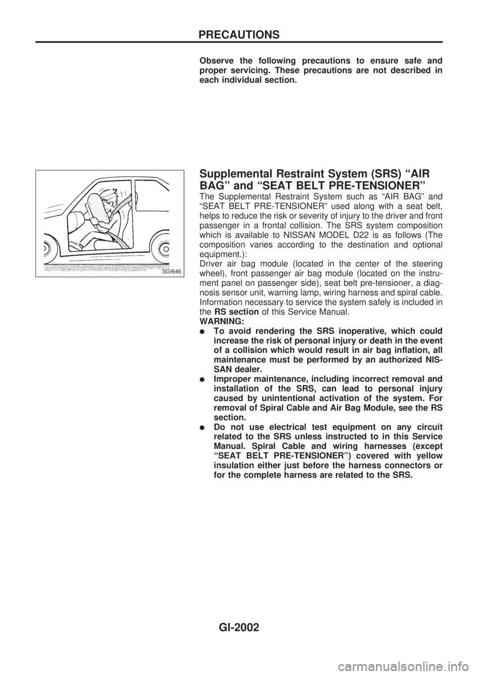
The Supplemental Restraint System such as ªAIR BAGº and
ªSEAT BELT PRE-TENSIONERº used along with a seat belt,
helps to reduce the risk or severity of injury to the driver and front
passenger in a frontal collision. The SRS system composition
which is available to NISSAN MODEL D22 is as follows (The
composition varies according to the destination and optional
equipment.):
Driver air bag module (located in the center of the steering
wheel), front passenger air bag module (located on the instru-
ment panel on passenger side), seat belt pre-tensioner, a diag-
nosis sensor unit, warning lamp, wiring harness and spiral cable.
Information necessary to service the system safely is included in
theRS sectionof this Service Manual.
WARNING:
lTo avoid rendering the SRS inoperative, which could
increase the risk of personal injury or death in the event
of a collision which would result in air bag inflation, all
maintenance must be performed by an authorized NIS-
SAN dealer.
lImproper maintenance, including incorrect removal and
installation of the SRS, can lead to personal injury
caused by unintentional activation of the system. For
removal of Spiral Cable and Air Bag Module, see the RS
section.
lDo not use electrical test equipment on any circuit
related to the SRS unless instructed to in this Service
Manual. Spiral Cable and wiring harnesses (except
ªSEAT BELT PRE-TENSIONERº) covered with yellow
insulation either just before the harness connectors or
for the complete harness are related to the SRS.
SGI646
PRECAUTIONS
GI-2002
Page 501 of 666
HEATER&
AIR CONDITIONER
SECTION
HA
MODIFICATION NOTICE:
lWiring Diagrams for manual A/C have been changed.
lAuto A/C has been added to RHD models for Europe.
lAuto A/C of LHD models for Europe have been changed.
CONTENTS
MANUAL AND AUTO
PRECAUTIONS AND PREPARATION ............... 2002
Supplemental Restraint System (SRS) ²AIR
BAG ²and ²SEAT BELT PRE-TENSIONER ².. 2002
MANUAL
TROUBLE DIAGNOSES ..................................... 2003
Wiring Diagram - HEATER -............................ 2003
Circuit Diagram - Air Conditioner..................... 2004
Wiring Diagram - A/C, M -/Except for KA
Engine Models ................................................. 2005
Wiring Diagram - A/C, M -/KA Engine LHD
Models.............................................................. 2008
Wiring Diagram - A/C, M -/KA Engine RHD
Models.............................................................. 2011
Magnet Clutch .................................................. 2014
AUTO
DESCRIPTION..................................................... 2023
Introduction ...................................................... 2023
Features ........................................................... 2023
Overview of Control System ............................ 2024
Control Operation............................................. 2024
TROUBLE DIAGNOSES ..................................... 2026 Component Location ........................................ 2026
Circuit Diagram ................................................ 2027
Wiring Diagram - A/C, A -................................ 2028
Auto Amp. Terminals and Reference Value .... 2032
Self-diagnosis................................................... 2034
How to Perform Trouble Diagnoses for Quick
and Accurate Repair ........................................ 2040
Operational Check ........................................... 2041
A/C System ...................................................... 2045
Mode Door Motor ............................................. 2047
Air Mix Door Motor........................................... 2052
Intake Door Motor ............................................ 2058
Blower Motor .................................................... 2062
Magnet Clutch .................................................. 2068
Insufficient Cooling........................................... 2075
Insufficient Heating .......................................... 2076
Noise ................................................................ 2077
Self-diagnosis................................................... 2078
Memory Function ............................................. 2079
Ambient Sensor ............................................... 2080
In-vehicle Sensor ............................................. 2082
Aspirator Motor ................................................ 2084
Sunload Sensor ............................................... 2084
Intake Sensor ................................................... 2087
When you read wiring diagrams:
+
Read GI section, ªHOW TO READ WIRING DIAGRAMSº.
+ See EL section, ªPOWER SUPPLY ROUTINGº for power distribution circuit.
When you perform trouble diagnoses, read GI section, ªHOW TO FOLLOW FLOW
CHART IN TROUBLE DIAGNOSESº and ªHOW TO PERFORM EFFICIENT DIAGNOSIS
FOR AN ELECTRICAL INCIDENTº.
HA