1999 NISSAN PICK-UP reset
[x] Cancel search: resetPage 34 of 666
BODY&TRIM
SECTION
BT
MODIFICATION NOTICE:
lThe instrument panel has been changed.
lThe body side trim has been changed.
lThe headlining has been changed.
lA jump seat has been added.
lAn auto reverse function has been added to the driver's door window.
CONTENTS
PRECAUTIONS ................................................... 2002
Supplemental Restraint System (SRS) ``AIR
BAG'' and ``SEAT BELT PRE-TENSIONER'' .. 2002
DOOR ................................................................... 2003
Front Door Limit Switch Reset (Driver side
only) ................................................................. 2003 INSTRUMENT PANEL
......................................... 2004
INTERIOR TRIM .................................................. 2007
Side and Floor Trim ......................................... 2007
Roof Trim ......................................................... 2010
SEAT .................................................................... 2012
Jump Seat - King Cab Model .......................... 2012
BT
Page 36 of 666
Front Door Limit Switch Reset (Driver side
only)
RESET CONDITIONS
After each of the following operations are performed, reset the
limit switch (with built-in motor).
lRegulator removal and installation
lRemoval of motor from regulator
lOperation of regulator as a single unit
lDoor glass removal and installation
lGlass run removal and installation
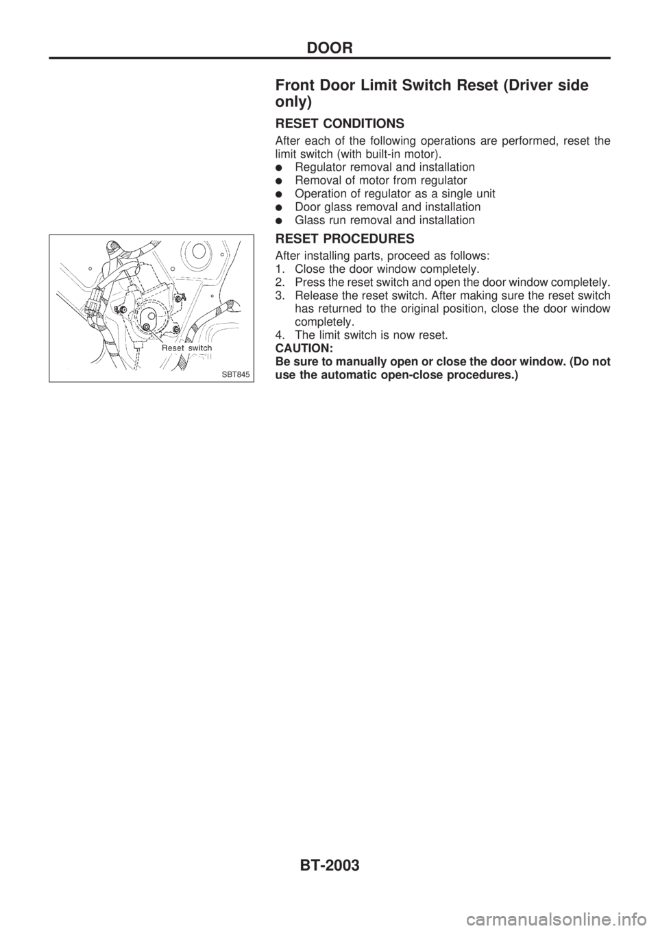
RESET PROCEDURES
After installing parts, proceed as follows:
1. Close the door window completely.
2. Press the reset switch and open the door window completely.
3. Release the reset switch. After making sure the reset switch
has returned to the original position, close the door window
completely.
4. The limit switch is now reset.
CAUTION:
Be sure to manually open or close the door window. (Do not
use the automatic open-close procedures.)
SBT845
DOOR
BT-2003
Page 200 of 666
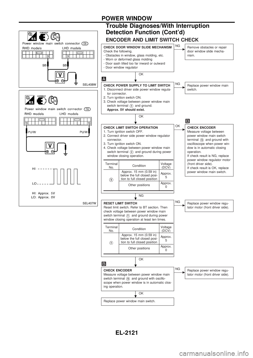
ENCODER AND LIMIT SWITCH CHECK
CHECK DOOR WINDOW SLIDE MECHANISM
Check the following.
- Obstacles in window, glass molding, etc.
- Worn or deformed glass molding
- Door sash tilted too far inward or outward
- Door window regulator
OK
cNG
Remove obstacles or repair
door window slide mecha-
nism.
CHECK POWER SUPPLY TO LIMIT SWITCH
1. Disconnect driver side power window regula-
tor connector.
2. Turn ignition switch ON.
3. Check voltage between power window main
switch terminal
V9and ground.
Approx. 5V should exist.
OK
cNG
Replace power window main
switch.
CHECK LIMIT SWITCH OPERATION
1. Turn ignition switch OFF.
2. Connect driver side power window regulator
connector.
3. Turn ignition switch ON.
4. Check voltage between power window main
switch terminal
V9and ground during power
window closing operation.
NG
cOK
CHECK ENCODER
Measure voltage between
power window main switch
terminal
V16and ground with
oscilloscope when power win-
dow is in automatic closing
operation.
If check result is NG, replace
power window regulator motor
(front driver side).
If check result is OK, replace
power window main switch.
RESET LIMIT SWITCH
Reset limit switch. Refer to BT section. Then
check voltage between power window main
switch terminal
V9and ground during power
window closing operation at least ten times.
OK
cNG
Replace power window regu-
lator motor (front driver side).
CHECK ENCODER
Measure voltage between power window main
switch terminal
V16and ground with oscillo-
scope when power window is in automatic clos-
ing operation.
OK
cNG
Replace power window regu-
lator motor (front driver side).
Replace power window main switch.
Terminal
No.ConditionVoltage
(DCV)
V9
Approx. 15 mm (0.59 in)
below the full closed posi-
tion to full closed positionApprox.
5
Other positionsApprox.
0
Terminal
No.ConditionVoltage
(DCV)
V9
Approx. 15 mm (0.59 in)
below the full closed posi-
tion to full closed positionApprox.
5
Other positionsApprox.
0
SEL408W
SEL407W
.
.
.
.
.
POWER WINDOW
Trouble Diagnoses/With Interruption
Detection Function (Cont'd)
EL-2121
Page 372 of 666
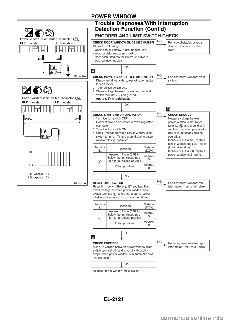
ENCODER AND LIMIT SWITCH CHECK
CHECK DOOR WINDOW SLIDE MECHANISM
Check the following.
- Obstacles in window, glass molding, etc.
- Worn or deformed glass molding
- Door sash tilted too far inward or outward
- Door window regulator
OK
cNG
Remove obstacles or repair
door window slide mecha-
nism.
CHECK POWER SUPPLY TO LIMIT SWITCH
1. Disconnect driver side power window regula-
tor connector.
2. Turn ignition switch ON.
3. Check voltage between power window main
switch terminal
V9and ground.
Approx. 5V should exist.
OK
cNG
Replace power window main
switch.
CHECK LIMIT SWITCH OPERATION
1. Turn ignition switch OFF.
2. Connect driver side power window regulator
connector.
3. Turn ignition switch ON.
4. Check voltage between power window main
switch terminal
V9and ground during power
window closing operation.
NG
cOK
CHECK ENCODER
Measure voltage between
power window main switch
terminal
V16and ground with
oscilloscope when power win-
dow is in automatic closing
operation.
If check result is NG, replace
power window regulator motor
(front driver side).
If check result is OK, replace
power window main switch.
RESET LIMIT SWITCH
Reset limit switch. Refer to BT section. Then
check voltage between power window main
switch terminal
V9and ground during power
window closing operation at least ten times.
OK
cNG
Replace power window regu-
lator motor (front driver side).
CHECK ENCODER
Measure voltage between power window main
switch terminal
V16and ground with oscillo-
scope when power window is in automatic clos-
ing operation.
OK
cNG
Replace power window regu-
lator motor (front driver side).
Replace power window main switch.
Terminal
No.ConditionVoltage
(DCV)
V9
Approx. 15 mm (0.59 in)
below the full closed posi-
tion to full closed positionApprox.
5
Other positionsApprox.
0
Terminal
No.ConditionVoltage
(DCV)
V9
Approx. 15 mm (0.59 in)
below the full closed posi-
tion to full closed positionApprox.
5
Other positionsApprox.
0
SEL408W
SEL407W
.
.
.
.
.
POWER WINDOW
Trouble Diagnoses/With Interruption
Detection Function (Cont'd)
EL-2121
Page 637 of 666
Trouble Diagnoses Introduction
CAUTION:
lDo not use electrical test equipment to check SRS harness connectors unless instructed to in
this Service Manual. SRS wiring harnesses can be identified by yellow harness protector or yel-
low insulation tape before the harness connectors.
lDo not attempt to repair, splice or modify the SRS wiring harness. If the harness is damaged,
replace it with a new one.
lKeep ground portion clean.
DIAGNOSIS FUNCTION
The SRS self-diagnosis results can be read by using ``AIR BAG'' warning lamp and/or CONSULT. The
reading of these results is accomplished using one of two modes Ð ``User mode'' and ``Diagnosis mode''.
The User mode is exclusively prepared for the customer (driver). This mode warns the driver of a system
malfunction through the operation of the ``AIR BAG'' warning lamp.
The Diagnosis mode allows the technician to locate and inspect the malfunctioning part.
The mode applications for the ``AIR BAG'' warning lamp and CONSULT are as follows:
User mode Diagnosis mode Display type
``AIR BAG'' warning lamp X X ON-OFF operation
DIAGNOSIS MODE FOR CONSULT
l``SELF-DIAG [CURRENT]''
A current Self-diagnosis result (also indicated by the warning lamp flashes in the Diagnosis mode) is
displayed on the CONSULT screen in real time. This refers to a malfunctioning part requiring repairs.
l``SELF-DIAG [PAST]''
Diagnosis results previously stored in the memory are displayed on the CONSULT screen. The stored
results are not erased until memory erasing is executed.
l``TROUBLE DIAG RECORD''
With TROUBLE DIAG RECORD, diagnosis results previously erased by a reset operation can be dis-
played on the CONSULT screen.
l``ECU DISCRIMINATED NO.''
The diagnosis sensor unit for each vehicle model is assigned with its own, individual classification number.
This number will be displayed on the CONSULT screen, as shown at left. When replacing the diagnosis
sensor unit, refer to the part number for the compatibility. After installation, replacement with a correct unit
can be checked by confirming this classification number on the CONSULT screen. The diagnosis sensor
unit classification number varies depending on SRS configuration.
For NISSAN MODEL D22, the diagnosis sensor unit classification numbers assigned are as follows.
MODEL ECU DISCRIMINATED NO.
Single air bag 5A0B
Dual air bag 5A0A
TROUBLE DIAGNOSES Ð Supplemental Restraint System (SRS)
RS-2015
Page 655 of 666
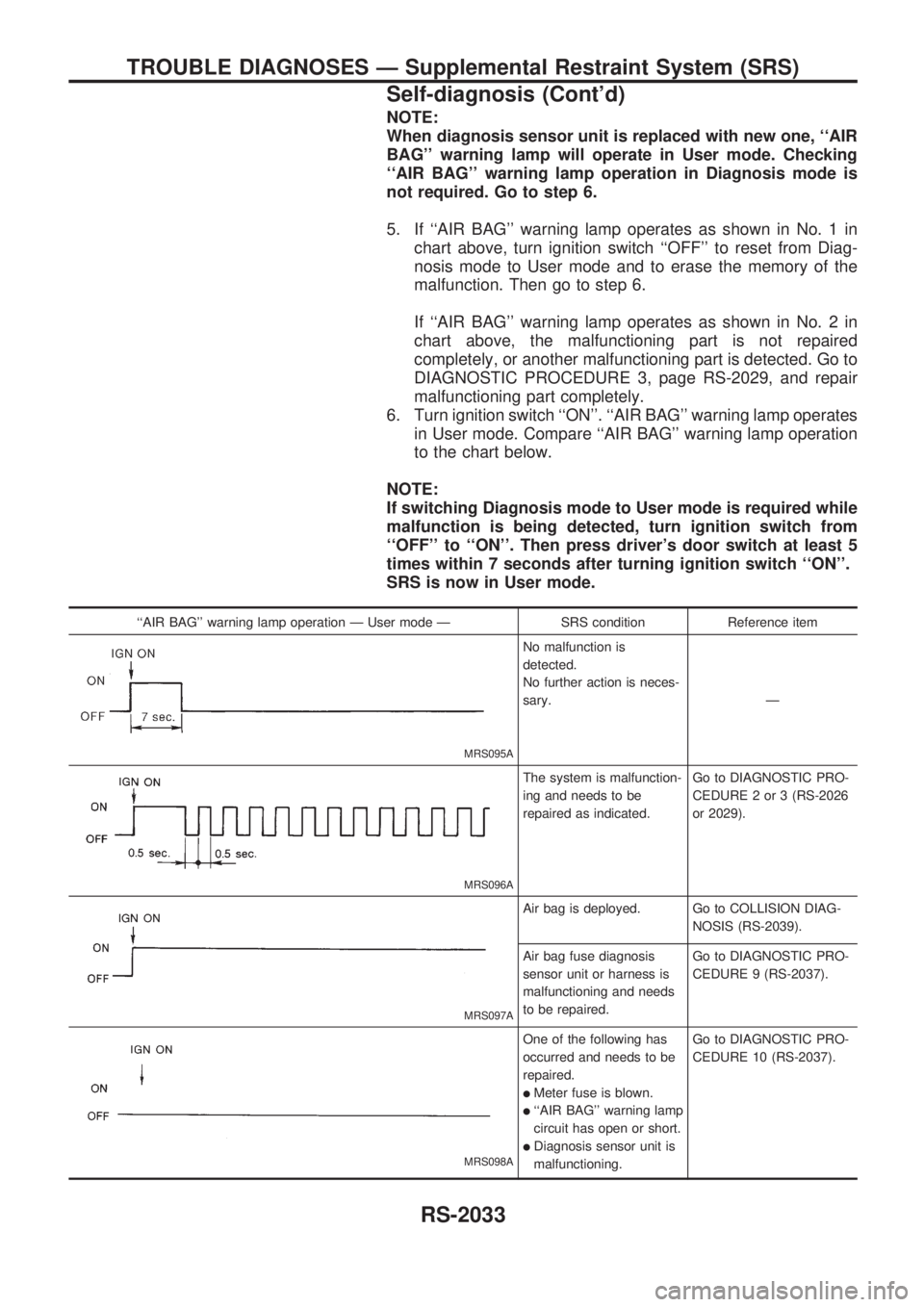
NOTE:
When diagnosis sensor unit is replaced with new one, ``AIR
BAG'' warning lamp will operate in User mode. Checking
``AIR BAG'' warning lamp operation in Diagnosis mode is
not required. Go to step 6.
5. If ``AIR BAG'' warning lamp operates as shown in No. 1 in
chart above, turn ignition switch ``OFF'' to reset from Diag-
nosis mode to User mode and to erase the memory of the
malfunction. Then go to step 6.
If ``AIR BAG'' warning lamp operates as shown in No. 2 in
chart above, the malfunctioning part is not repaired
completely, or another malfunctioning part is detected. Go to
DIAGNOSTIC PROCEDURE 3, page RS-2029, and repair
malfunctioning part completely.
6. Turn ignition switch ``ON''. ``AIR BAG'' warning lamp operates
in User mode. Compare ``AIR BAG'' warning lamp operation
to the chart below.
NOTE:
If switching Diagnosis mode to User mode is required while
malfunction is being detected, turn ignition switch from
``OFF'' to ``ON''. Then press driver's door switch at least 5
times within 7 seconds after turning ignition switch ``ON''.
SRS is now in User mode.
``AIR BAG'' warning lamp operation Ð User mode Ð SRS condition Reference item
MRS095A
No malfunction is
detected.
No further action is neces-
sary.Ð
MRS096A
The system is malfunction-
ing and needs to be
repaired as indicated.Go to DIAGNOSTIC PRO-
CEDURE 2 or 3 (RS-2026
or 2029).
MRS097A
Air bag is deployed. Go to COLLISION DIAG-
NOSIS (RS-2039).
Air bag fuse diagnosis
sensor unit or harness is
malfunctioning and needs
to be repaired.Go to DIAGNOSTIC PRO-
CEDURE 9 (RS-2037).
MRS098A
One of the following has
occurred and needs to be
repaired.
lMeter fuse is blown.
l``AIR BAG'' warning lamp
circuit has open or short.
lDiagnosis sensor unit is
malfunctioning.Go to DIAGNOSTIC PRO-
CEDURE 10 (RS-2037).
TROUBLE DIAGNOSES Ð Supplemental Restraint System (SRS)
Self-diagnosis (Cont'd)
RS-2033
Page 657 of 666
![NISSAN PICK-UP 1999 Repair Manual 5. Touch ``AIRBAG.
6. Touch ``SELF-DIAG [PAST].
7. If diagnostic codes are displayed on ``SELF-DIAG [PAST],
go to step 10.
If no malfunction is detected on ``SELF-DIAG [PAST], touch
``BACK a NISSAN PICK-UP 1999 Repair Manual 5. Touch ``AIRBAG.
6. Touch ``SELF-DIAG [PAST].
7. If diagnostic codes are displayed on ``SELF-DIAG [PAST],
go to step 10.
If no malfunction is detected on ``SELF-DIAG [PAST], touch
``BACK a](/manual-img/5/57373/w960_57373-656.png)
5. Touch ``AIRBAG''.
6. Touch ``SELF-DIAG [PAST]''.
7. If diagnostic codes are displayed on ``SELF-DIAG [PAST]'',
go to step 10.
If no malfunction is detected on ``SELF-DIAG [PAST]'', touch
``BACK'' and go back to ``SELECT DIAG MODE''.
8. Touch ``TROUBLE DIAG RECORD''.
NOTE:
With ``TROUBLE DIAG RECORD'', diagnosis results previ-
ously erased by a reset operation can be displayed.
SRS074
SRS050
SRS054
SRS062
SRS055
TROUBLE DIAGNOSES Ð Supplemental Restraint System (SRS)
Self-diagnosis (Cont'd)
RS-2035