1999 NISSAN PICK-UP wheel alignment
[x] Cancel search: wheel alignmentPage 485 of 666

FRONTAXLE&
FRONT SUSPENSION
SECTION
FA
MODIFICATION NOTICE:
lTightening torque have been changed.
lWheel alignment have been changed.
CONTENTS
FRONT SUSPENSION ........................................ 2002
SERVICE DATA AND SPECIFICATIONS
(SDS) .................................................................... 2004 Inspection and Adjustment .............................. 2004
FA
Page 488 of 666

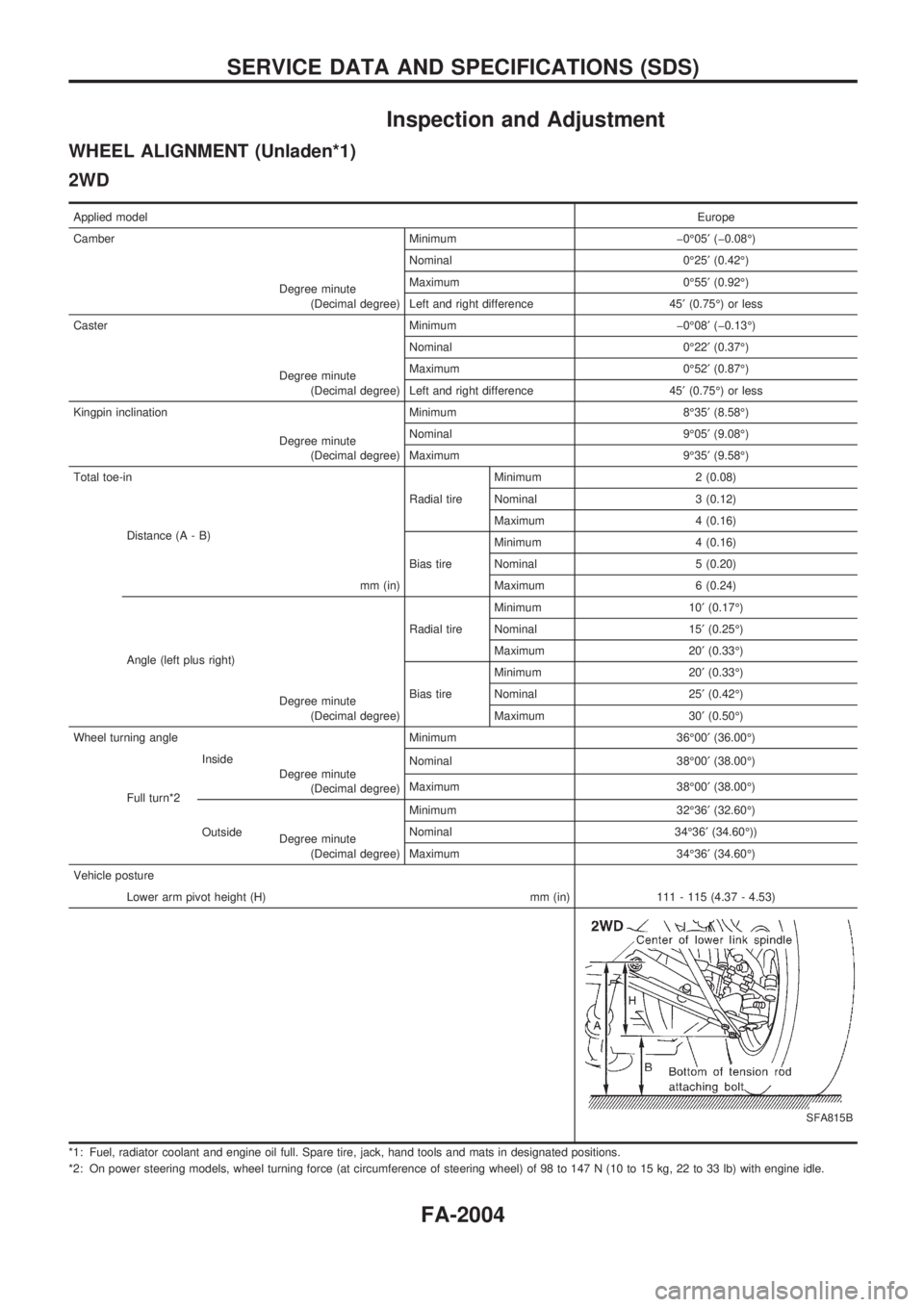
Inspection and Adjustment
WHEEL ALIGNMENT (Unladen*1)
2WD
Applied modelEurope
Camber Minimum þ0É05¢(þ0.08É)
Degree minute
(Decimal degree)Nominal 0É25¢(0.42É)
Maximum 0É55¢(0.92É)
Left and right difference 45¢(0.75É) or less
Caster Minimum þ0É08¢(þ0.13É)
Degree minute
(Decimal degree)Nominal 0É22¢(0.37É)
Maximum 0É52¢(0.87É)
Left and right difference 45¢(0.75É) or less
Kingpin inclination Minimum 8É35¢(8.58É)
Degree minute
(Decimal degree)Nominal 9É05¢(9.08É)
Maximum 9É35¢(9.58É)
Total toe-in
Radial tireMinimum 2 (0.08)
Distance (A - B)
mm (in)Nominal 3 (0.12)
Maximum 4 (0.16)
Bias tireMinimum 4 (0.16)
Nominal 5 (0.20)
Maximum 6 (0.24)
Angle (left plus right)
Degree minute
(Decimal degree)Radial tireMinimum 10¢(0.17É)
Nominal 15¢(0.25É)
Maximum 20¢(0.33É)
Bias tireMinimum 20¢(0.33É)
Nominal 25¢(0.42É)
Maximum 30¢(0.50É)
Wheel turning angle Minimum 36É00¢(36.00É)
Full turn*2Inside
Degree minute
(Decimal degree)Nominal 38É00¢(38.00É)
Maximum 38É00¢(38.00É)
OutsideMinimum 32É36¢(32.60É)
Degree minute
(Decimal degree)Nominal 34É36¢(34.60É))
Maximum 34É36¢(34.60É)
Vehicle posture
Lower arm pivot height (H) mm (in) 111 - 115 (4.37 - 4.53)
SFA815B
*1: Fuel, radiator coolant and engine oil full. Spare tire, jack, hand tools and mats in designated positions.
*2: On power steering models, wheel turning force (at circumference of steering wheel) of 98 to 147 N (10 to 15 kg, 22 to 33 lb) with engine idle.
SERVICE DATA AND SPECIFICATIONS (SDS)
FA-2004
Page 629 of 666

lRemove air bag module from steering wheel, instrument
panel or seat back. Check harness cover and connectors for
damage, terminals for deformities, and harness for binding.
lInstall driver air bag module to steering wheel to check fit or
alignment with the wheel.
lCheck steering wheel for excessive free play.
lInstall passenger air bag module to instrument panel to
check fit or alignment with the instrument panel.
(3) Spiral cable
lCheck spiral cable for dents, cracks, or deformities.
lCheck connectors and protective tape for damage.
lCheck steering wheel for noise, binding or heavy operation.
(4) Main harness and air bag harness
lCheck connectors for poor connections, damage, and termi-
nals for deformities.
lCheck harnesses for binding, chafing or cut.
CAUTION:
Replace previously used special bolts and ground bolt with
new ones.
Removal and Installation Ð Diagnosis
Sensor Unit
CAUTION:
lBefore servicing SRS, turn the ignition switch off, disconnect both battery cables and wait at least
3 minutes.
lDo not use old special bolts and nuts coated with bonding agent after removal; replace with new
ones.
lCheck diagnosis sensor unit for proper installation.
lCheck diagnosis sensor unit to ensure it is free of deformities, dents, cracks or rust. If it shows
any visible signs of damage, replace it with a new one.
lCheck diagnosis sensor unit brackets to ensure they are free of deformities and rust.
lAfter replacement of diagnosis sensor unit, check SRS function and perform self-diagnosis for
SRS. Refer to ``Self-diagnosis'' for details. (RS-2025)
lDo not attempt to disassemble diagnosis sensor unit.
lReplace diagnosis sensor unit and if it has been dropped or sustained an impact.
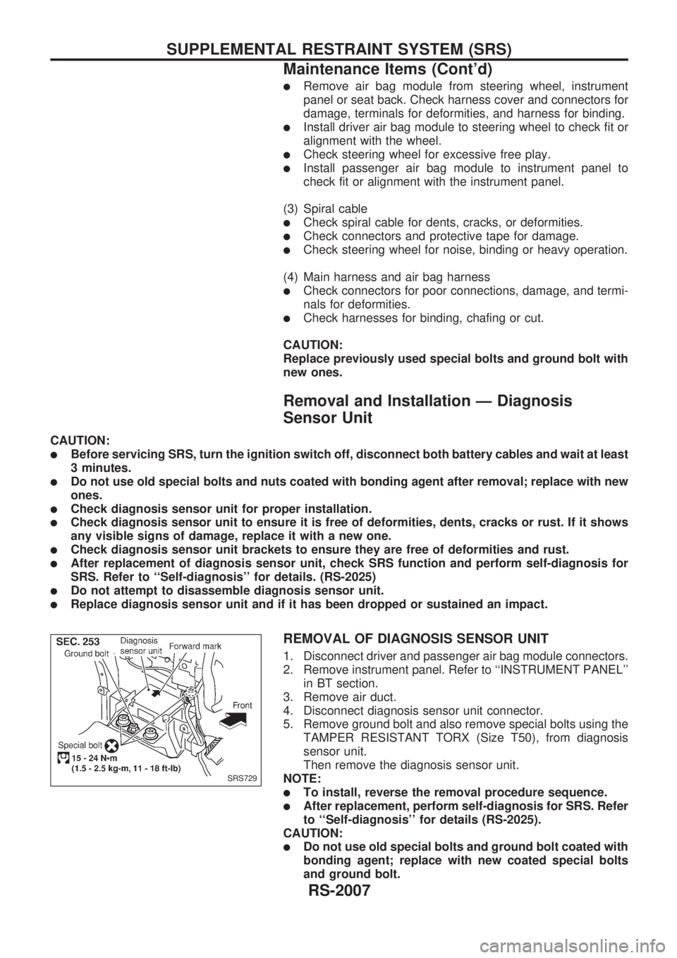
REMOVAL OF DIAGNOSIS SENSOR UNIT
1. Disconnect driver and passenger air bag module connectors.
2. Remove instrument panel. Refer to ``INSTRUMENT PANEL''
in BT section.
3. Remove air duct.
4. Disconnect diagnosis sensor unit connector.
5. Remove ground bolt and also remove special bolts using the
TAMPER RESISTANT TORX (Size T50), from diagnosis
sensor unit.
Then remove the diagnosis sensor unit.
NOTE:
lTo install, reverse the removal procedure sequence.
lAfter replacement, perform self-diagnosis for SRS. Refer
to ``Self-diagnosis'' for details (RS-2025).
CAUTION:
lDo not use old special bolts and ground bolt coated with
bonding agent; replace with new coated special bolts
and ground bolt.
SRS729
SUPPLEMENTAL RESTRAINT SYSTEM (SRS)
Maintenance Items (Cont'd)
RS-2007
Page 661 of 666

FOR FRONTAL COLLISION
To repair the SRS for a frontal collision, perform the following steps.
When SRS is activated in a collision:
V01Replace the diagnosis sensor unit.
V02Remove the air bag modules.
V03Check the SRS components using the table shown below:
lReplace any SRS components showing visible signs of damage (dents, cracks, deformation).
V04Install new air bag modules.
V05Conduct self-diagnosis using CONSULT, and ``AIR BAG'' warning lamp. Refer to ``Self-diagnosis'' for
details (RS-2025). Ensure entire SRS operates properly.
When SRS is not activated in a collision:
V01Check the SRS components using the table shown below:
lReplace any SRS components showing visible signs of damage (dents, cracks, deformation).
V02Conduct self-diagnosis using CONSULT, and ``AIR BAG'' warning lamp. Refer to ``Self-diagnosis'' for
details (RS-2025). Ensure entire SRS operates properly.
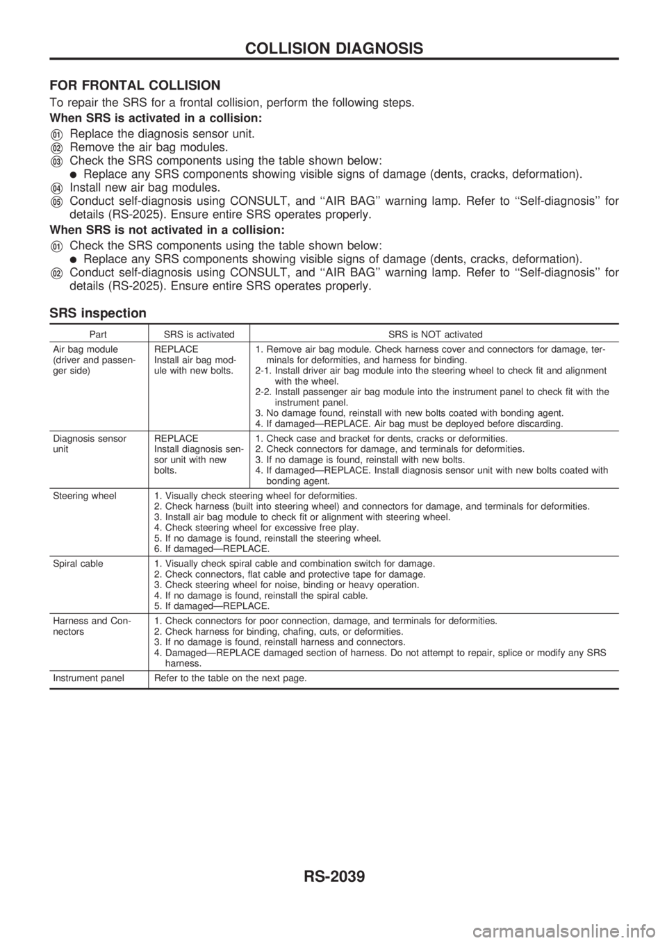
SRS inspection
Part SRS is activated SRS is NOT activated
Air bag module
(driver and passen-
ger side)REPLACE
Install air bag mod-
ule with new bolts.1. Remove air bag module. Check harness cover and connectors for damage, ter-
minals for deformities, and harness for binding.
2-1. Install driver air bag module into the steering wheel to check fit and alignment
with the wheel.
2-2. Install passenger air bag module into the instrument panel to check fit with the
instrument panel.
3. No damage found, reinstall with new bolts coated with bonding agent.
4. If damagedÐREPLACE. Air bag must be deployed before discarding.
Diagnosis sensor
unitREPLACE
Install diagnosis sen-
sor unit with new
bolts.1. Check case and bracket for dents, cracks or deformities.
2. Check connectors for damage, and terminals for deformities.
3. If no damage is found, reinstall with new bolts.
4. If damagedÐREPLACE. Install diagnosis sensor unit with new bolts coated with
bonding agent.
Steering wheel 1. Visually check steering wheel for deformities.
2. Check harness (built into steering wheel) and connectors for damage, and terminals for deformities.
3. Install air bag module to check fit or alignment with steering wheel.
4. Check steering wheel for excessive free play.
5. If no damage is found, reinstall the steering wheel.
6. If damagedÐREPLACE.
Spiral cable 1. Visually check spiral cable and combination switch for damage.
2. Check connectors, flat cable and protective tape for damage.
3. Check steering wheel for noise, binding or heavy operation.
4. If no damage is found, reinstall the spiral cable.
5. If damagedÐREPLACE.
Harness and Con-
nectors1. Check connectors for poor connection, damage, and terminals for deformities.
2. Check harness for binding, chafing, cuts, or deformities.
3. If no damage is found, reinstall harness and connectors.
4. DamagedÐREPLACE damaged section of harness. Do not attempt to repair, splice or modify any SRS
harness.
Instrument panel Refer to the table on the next page.
COLLISION DIAGNOSIS
RS-2039