1999 DODGE NEON fuel pressure
[x] Cancel search: fuel pressurePage 822 of 1200
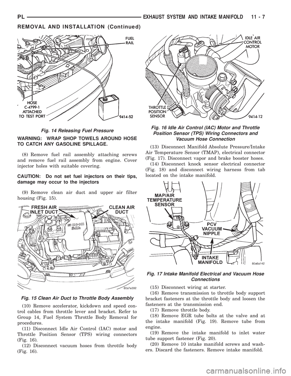
WARNING: WRAP SHOP TOWELS AROUND HOSE
TO CATCH ANY GASOLINE SPILLAGE.
(8) Remove fuel rail assembly attaching screws
and remove fuel rail assembly from engine. Cover
injector holes with suitable covering.
CAUTION: Do not set fuel injectors on their tips,
damage may occur to the injectors
(9) Remove clean air duct and upper air filter
housing (Fig. 15).
(10) Remove accelerator, kickdown and speed con-
trol cables from throttle lever and bracket. Refer to
Group 14, Fuel System Throttle Body Removal for
procedures.
(11) Disconnect Idle Air Control (IAC) motor and
Throttle Position Sensor (TPS) wiring connectors
(Fig. 16).
(12) Disconnect vacuum hoses from throttle body
(Fig. 16).(13) Disconnect Manifold Absolute Pressure/Intake
Air Temperature Sensor (TMAP), electrical connector
(Fig. 17). Disconnect vapor and brake booster hoses.
(14) Disconnect knock sensor electrical connector
(Fig. 18) and disconnect wiring harness from tab
located on the intake manifold.
(15) Disconnect wiring at starter.
(16) Remove transmission to throttle body support
bracket fasteners at the throttle body and loosen the
fasteners at the transmission end.
(17) Remove throttle body.
(18) Remove EGR tube bolts at the valve and at
the intake manifold (Fig. 19). Remove tube from
engine.
(19) Remove the intake manifold to inlet water
tube support fastener (Fig. 20).
(20) Remove 10 intake manifold screws and wash-
ers. Discard the fasteners. Remove intake manifold.
Fig. 14 Releasing Fuel Pressure
Fig. 15 Clean Air Duct to Throttle Body Assembly
Fig. 16 Idle Air Control (IAC) Motor and Throttle
Position Sensor (TPS) Wiring Connectors and
Vacuum Hose Connection
Fig. 17 Intake Manifold Electrical and Vacuum Hose
Connections
PLEXHAUST SYSTEM AND INTAKE MANIFOLD 11 - 7
REMOVAL AND INSTALLATION (Continued)
Page 823 of 1200
INSTALLATION
Before installing manifold. Clean all mating sur-
faces. Replace all seals, with new seals. All intakemanifold fasteners and washers are to be discarded
andNEWfasteners and washers are to be used.
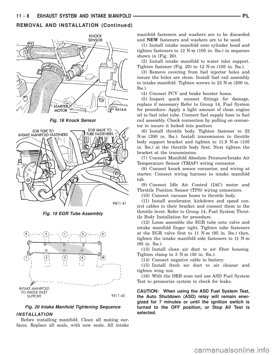
(1) Install intake manifold onto cylinder head and
tighten fasteners to 12 N´m (105 in. lbs.) in sequence
shown in (Fig. 20).
(2) Install intake manifold to water inlet support.
Tighten fastener (Fig. 20) to 12 N´m (105 in. lbs.).
(3) Remove covering from fuel injector holes and
insure the holes are clean. Install fuel rail assembly
to intake manifold. Tighten screws to 23 N´m (200 in.
lbs.).
(4) Connect PCV and brake booster hoses.
(5) Inspect quick connect fittings for damage,
replace if necessary Refer to Group 14, Fuel System
for procedure. Apply a light amount of clean engine
oil to fuel inlet tube. Connect fuel supply hose to fuel
rail assembly. Check connection by pulling on connec-
tor to insure it locked into position.
(6) Install throttle body. Tighten fastener to 22
N´m (200 in. lbs.). Install transmission to throttle
body support bracket and tighten to 11.9 N´m (105
in. lbs.) at the throttle body first. Next tighten the
bracket at the transmission.
(7) Connect Manifold Absolute Pressure/Intake Air
Temperature Sensor (TMAP) wiring connector.
(8) Connect knock sensor connector, and wiring at
starter. Connect wiring harness to intake manifold
tab.
(9) Connect Idle Air Control (IAC) motor and
Throttle Position Sensor (TPS) wiring connectors.
(10) Connect vacuum hoses to throttle body.
(11) Install accelerator, kickdown and speed con-
trol cables to their bracket and connect them to the
throttle lever. Refer to Group 14, Fuel System Throt-
tle Body Installation for procedure.
(12) Loose assemble the EGR tube onto valve and
intake manifold finger tight. Tighten tube fasteners
at the EGR valve first to 11 N´m (95 in. lbs.) then,
tighten the intake manifold side fasteners to 11 N´m
(95 in. lbs.).
(13) Install clean air duct to air filter housing.
Tighten clamp to 3 N´m (30 in. lbs.).
(14) Connect negative cable to battery.
(15) Install fresh air duct to air cleaner and
tighten wing nut.
(16) With the DRB scan tool use ASD Fuel System
Test to pressurize system to check for leaks.
CAUTION: When using the ASD Fuel System Test,
the Auto Shutdown (ASD) relay will remain ener-
gized for 7 minutes or until the ignition switch is
turned to the OFF position, or Stop All Test is
selected.
Fig. 18 Knock Sensor
Fig. 19 EGR Tube Assembly
Fig. 20 Intake Manifold Tightening Sequence
11 - 8 EXHAUST SYSTEM AND INTAKE MANIFOLDPL
REMOVAL AND INSTALLATION (Continued)
Page 824 of 1200

INTAKE MANIFOLDÐDOHC ENGINE
REMOVAL
WARNING: RELEASE FUEL SYSTEM PRESSURE
BEFORE SERVICING FUEL SYSTEM COMPONENTS.
SERVICE VEHICLES IN WELL VENTILATED AREAS
AND AVOID IGNITION SOURCES. NEVER SMOKE
WHILE SERVICING THE VEHICLE.
(1) Disconnect negative cable from battery.
(2) Remove fuel filler cap.
(3) Loosen wing nut on intake and remove fresh
air inlet duct (Fig. 23).
(4) Remove the protective cap from the fuel pres-
sure test port on the fuel rail (Fig. 21).
(5) Place the open end of fuel pressure release
hose, Special Tool C-4799-1, into an approved gaso-
line container. Connect the other end of hose to the
fuel pressure test port (Fig. 22). Fuel pressure will
bleed off through the hose into the gasoline con-
tainer. Fuel gauge C-4799-A contains hose C-4799-1.
(6) Disconnect the fuel supply line quick-connect at
the fuel tube assembly.
(7) Remove clean air inlet duct.WARNING: WRAP SHOP TOWELS AROUND HOSE
TO CATCH ANY GASOLINE SPILLAGE.
(8) Disconnect the coolant temperature sensor
(Fig. 24).
(9) Disconnect heater hose from intake manifold.
(10) Disconnect heater tube from bottom of intake
manifold.
(11) Disconnect upper radiator hose and coolant
recovery hose.
(12) Remove fuel rail assembly attaching screws
and remove fuel rail assembly from engine. Cover
injector holes with suitable covering.
CAUTION: Do not set fuel injectors on their tips,
damage may occur to the injectors
Fig. 21 Fuel Pressure Test PortÐTypical
Fig. 22 Releasing Fuel PressureÐTypical
Fig. 23 Fresh Air Inlet Duct
Fig. 24 Engine Coolant Temperature Sensor
PLEXHAUST SYSTEM AND INTAKE MANIFOLD 11 - 9
REMOVAL AND INSTALLATION (Continued)
Page 825 of 1200
(13) Remove accelerator, kickdown and speed con-
trol cables from throttle lever and bracket. Refer to
Group 14, Fuel System Throttle Body Removal for
procedures.
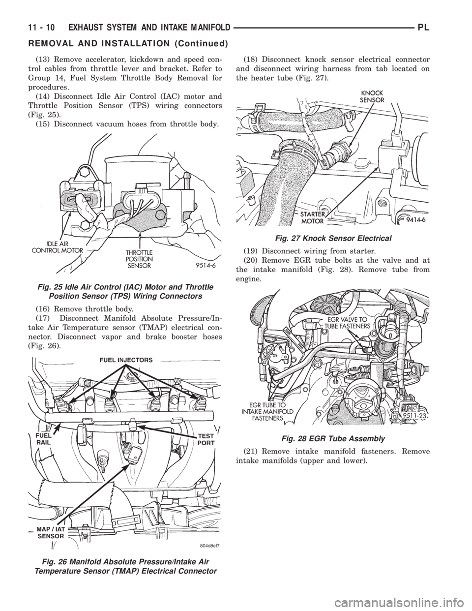
(14) Disconnect Idle Air Control (IAC) motor and
Throttle Position Sensor (TPS) wiring connectors
(Fig. 25).
(15) Disconnect vacuum hoses from throttle body.
(16) Remove throttle body.
(17) Disconnect Manifold Absolute Pressure/In-
take Air Temperature sensor (TMAP) electrical con-
nector. Disconnect vapor and brake booster hoses
(Fig. 26).(18) Disconnect knock sensor electrical connector
and disconnect wiring harness from tab located on
the heater tube (Fig. 27).
(19) Disconnect wiring from starter.
(20) Remove EGR tube bolts at the valve and at
the intake manifold (Fig. 28). Remove tube from
engine.
(21) Remove intake manifold fasteners. Remove
intake manifolds (upper and lower).
Fig. 25 Idle Air Control (IAC) Motor and Throttle
Position Sensor (TPS) Wiring Connectors
Fig. 26 Manifold Absolute Pressure/Intake Air
Temperature Sensor (TMAP) Electrical Connector
Fig. 27 Knock Sensor Electrical
Fig. 28 EGR Tube Assembly
11 - 10 EXHAUST SYSTEM AND INTAKE MANIFOLDPL
REMOVAL AND INSTALLATION (Continued)
Page 826 of 1200

INSTALLATION
Before installing manifolds. Clean all mating sur-
faces. Replace all gaskets, with new.
(1) Assemble lower manifold to upper (if sepa-
rated) and tighten bolts in sequence shown in (Fig.
29) to 28 N´m (250 in. lbs.).
(2) Install intake manifold onto cylinder head and
tighten fasteners to 28 N´m (250 in. lbs.) in sequence
shown in (Fig. 30).
(3) Remove covering from fuel injector holes and
insure the holes are clean. Install fuel rail assembly
to intake manifold. Tighten screws to 23 N´m (200 in.
lbs.).
(4) Connect PCV and brake booster hoses.
(5) Inspect quick connect fittings for damage,
replace if necessary Refer to Group 14, Fuel System
for procedure. Apply a light amount of clean engine
oil to fuel inlet tube. Connect fuel supply hose to fuel
rail assembly. Check connection by pulling on connec-
tor to insure it locked into position.
(6) Connect heater tube and hose to intake mani-
fold.
(7) Connect upper radiator hose and coolant recov-
ery hose.
(8) Connect coolant temperature sensor wiring con-
nector.
(9) Install throttle body. Tighten fastener to 22
N´m (200 in. lbs.).
(10) Connect Manifold Absolute Pressure/Intake
Air Temperature Sensor (TMAP) wiring connector.(11) Connect knock sensor connector and starter
wires. Connect wiring harness to heater tube tab.
(12) Connect Idle Air Control (IAC) motor and
Throttle Position Sensor (TPS) wiring connectors.
(13) Connect vacuum hoses to throttle body.
(14) Install accelerator, kickdown and speed con-
trol cables to their bracket and connect them to the
throttle lever. Refer to Group 14, Fuel System Throt-
tle Body Installation for procedure.
(15) Loose assemble the EGR tube onto valve and
intake manifold finger tight. Tighten tube fasteners
at the EGR valve first to 11 N´m (95 in. lbs.) then,
tighten the intake manifold side fasteners to 11 N´m
(95 in. lbs.).
(16) Install fresh air duct to air filter housing.
Tighten clamp to 3 N´m (25 in. lbs.).
(17) Connect negative cable to battery.
(18) With the DRB scan tool use ASD Fuel System
Test to pressurize system to check for leaks.
CAUTION: When using the ASD Fuel System Test,
the Auto Shutdown (ASD) relay will remain ener-
gized for 7 minutes or until the ignition switch is
turned to the OFF position, or Stop All Test is
selected.
EXHAUST MANIFOLD
REMOVAL
(1) Remove air cleaner assembly and bracket.
(2) Remove exhaust manifold heat shield (Fig. 31).
(3) Disconnect upstream heated oxygen sensor con-
nector.
Fig. 29 Lower Intake Manifold to Upper Tightening
Sequence
Fig. 30 Intake Manifold To Cylinder Head Tightening
Sequence
Fig. 31 Exhaust Manifold Heat Shield
PLEXHAUST SYSTEM AND INTAKE MANIFOLD 11 - 11
REMOVAL AND INSTALLATION (Continued)
Page 844 of 1200
FUEL DELIVERY SYSTEM
INDEX
page page
DESCRIPTION AND OPERATION
ELECTRIC FUEL PUMP.................... 4
FUEL DELIVERY SYSTEM.................. 3
FUEL FILTER/FUEL PRESSURE REGULATOR . . . 4
FUEL GAUGE SENDING UNIT............... 4
FUEL INJECTORS........................ 5
FUEL PUMP MODULE..................... 3
FUEL RAIL.............................. 4
FUEL TANK............................. 4
PRESSURE-VACUUM FILLER CAP........... 5
QUICK-CONNECT FITTINGS................ 5
ROLLOVER VALVES...................... 5
DIAGNOSIS AND TESTING
FUEL INJECTORS........................ 8
FUEL LEVEL SENSOR..................... 6
FUEL PUMP PRESSURE TEST.............. 6
SERVICE PROCEDURES
DRAINING FUEL TANK.................... 10
FUEL SYSTEM PRESSURE RELEASE
PROCEDURE......................... 10HOSES AND CLAMPS.................... 10
QUICK-CONNECT FITTINGS............... 11
REMOVAL AND INSTALLATION
ACCELERATOR PEDAL................... 17
AUTOMATIC SHUTDOWN RELAY........... 11
FUEL FILLER NECK...................... 16
FUEL FILLER TUBE ROLLOVER VALVE....... 16
FUEL FILTER / PRESSURE REGULATOR..... 12
FUEL INJECTORS....................... 14
FUEL LEVEL SENSOR.................... 13
FUEL PUMP INLET STRAINER............. 13
FUEL PUMP MODULE.................... 11
FUEL PUMP RELAY...................... 11
FUEL TANK............................ 15
THROTTLE CABLEÐAUTOMATIC
TRANSMISSION....................... 18
THROTTLE CABLEÐMANUAL TRANSMISSION . 17
SPECIFICATIONS
FUEL TANK CAPACITY................... 19
TORQUE.............................. 19
DESCRIPTION AND OPERATION
FUEL DELIVERY SYSTEM
The fuel delivery system consists of: the electric
fuel pump, fuel filter/fuel pressure regulator, fuel
tubes/lines/hoses, fuel rail, fuel injectors, fuel tank,
accelerator pedal and throttle cable.
A fuel return system is used on all models (all
engines). Fuel is returned through the fuel pump
module and back into the fuel tank through the fuel
filter/fuel pressure regulator. A separate fuel return
line from the engine to the tank is no longer used
with any engine.
The fuel tank assembly consists of: the fuel tank,
filler tube, fuel gauge sending unit/electric fuel pump
module, a pressure relief/rollover valve and a pres-
sure-vacuum filler cap.
Also to be considered part of the fuel system is the
evaporation control system. This is designed to
reduce the emission of fuel vapors into the atmo-
sphere. The description and function of the Evapora-
tive Control System is found in Group 25, Emission
Control Systems.
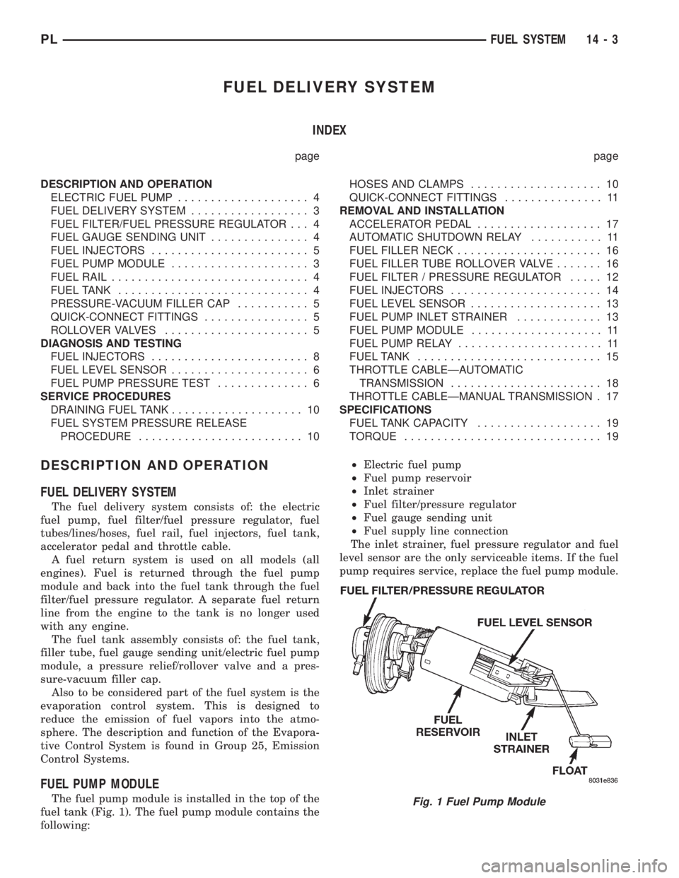
FUEL PUMP MODULE
The fuel pump module is installed in the top of the
fuel tank (Fig. 1). The fuel pump module contains the
following:²Electric fuel pump
²Fuel pump reservoir
²Inlet strainer
²Fuel filter/pressure regulator
²Fuel gauge sending unit
²Fuel supply line connection
The inlet strainer, fuel pressure regulator and fuel
level sensor are the only serviceable items. If the fuel
pump requires service, replace the fuel pump module.Fig. 1 Fuel Pump Module
PLFUEL SYSTEM 14 - 3
Page 845 of 1200
ELECTRIC FUEL PUMP
The electric fuel pump is located in and is part of
the fuel pump module. It is a positive displacement,
gerotor type, immersible pump with a permanent
magnet electric motor. The fuel pump module is sus-
pended in fuel in the fuel tank. The pump draws fuel
through a strainer and pushes it through the motor
to the outlet. The pump contains a check valve. The
valve, in the pump outlet, maintains pump pressure
during engine off conditions. The fuel pump relay
provides voltage to the fuel pump.
The fuel pump has a maximum deadheaded pres-
sure output of approximately 880 kPa (130 psi). The
regulator adjusts fuel system pressure to approxi-
mately 338 kPa (49 psi).
FUEL GAUGE SENDING UNIT
The fuel gauge sending unit (fuel level sensor) is
attached to the side of the fuel pump module. The
sending unit consists of a float, an arm, and a vari-
able resistor (track). The resistor track is used to
send electrical signals to the Powertrain Control
Module (PCM) for fuel gauge operation and for OBD
II emission requirements.
For fuel gauge operation:As fuel level
increases, the float and arm move up. This decreases
the sending unit resistance, causing the fuel gauge to
read full. As fuel level decreases, the float and arm
move down. This increases the sending unit resis-
tance causing the fuel gauge to read empty.
After this fuel level signal is sent to the PCM, the
PCM will transmit the data across the CCD bus cir-
cuits to the instrument panel. Here it is translated
into the appropriate fuel gauge level reading.
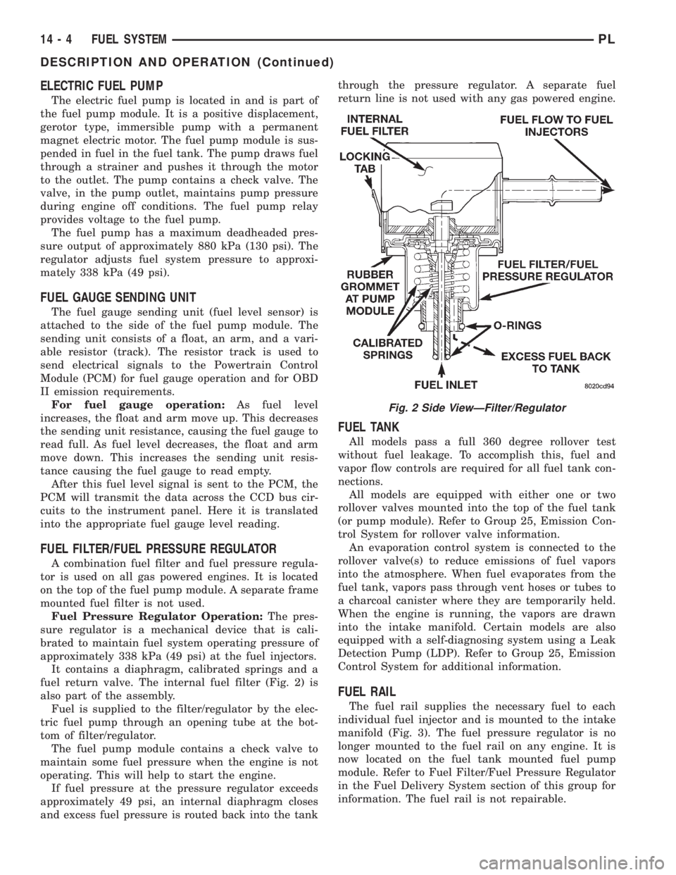
FUEL FILTER/FUEL PRESSURE REGULATOR
A combination fuel filter and fuel pressure regula-
tor is used on all gas powered engines. It is located
on the top of the fuel pump module. A separate frame
mounted fuel filter is not used.
Fuel Pressure Regulator Operation:The pres-
sure regulator is a mechanical device that is cali-
brated to maintain fuel system operating pressure of
approximately 338 kPa (49 psi) at the fuel injectors.
It contains a diaphragm, calibrated springs and a
fuel return valve. The internal fuel filter (Fig. 2) is
also part of the assembly.
Fuel is supplied to the filter/regulator by the elec-
tric fuel pump through an opening tube at the bot-
tom of filter/regulator.
The fuel pump module contains a check valve to
maintain some fuel pressure when the engine is not
operating. This will help to start the engine.
If fuel pressure at the pressure regulator exceeds
approximately 49 psi, an internal diaphragm closes
and excess fuel pressure is routed back into the tankthrough the pressure regulator. A separate fuel
return line is not used with any gas powered engine.
FUEL TANK
All models pass a full 360 degree rollover test
without fuel leakage. To accomplish this, fuel and
vapor flow controls are required for all fuel tank con-
nections.
All models are equipped with either one or two
rollover valves mounted into the top of the fuel tank
(or pump module). Refer to Group 25, Emission Con-
trol System for rollover valve information.
An evaporation control system is connected to the
rollover valve(s) to reduce emissions of fuel vapors
into the atmosphere. When fuel evaporates from the
fuel tank, vapors pass through vent hoses or tubes to
a charcoal canister where they are temporarily held.
When the engine is running, the vapors are drawn
into the intake manifold. Certain models are also
equipped with a self-diagnosing system using a Leak
Detection Pump (LDP). Refer to Group 25, Emission
Control System for additional information.
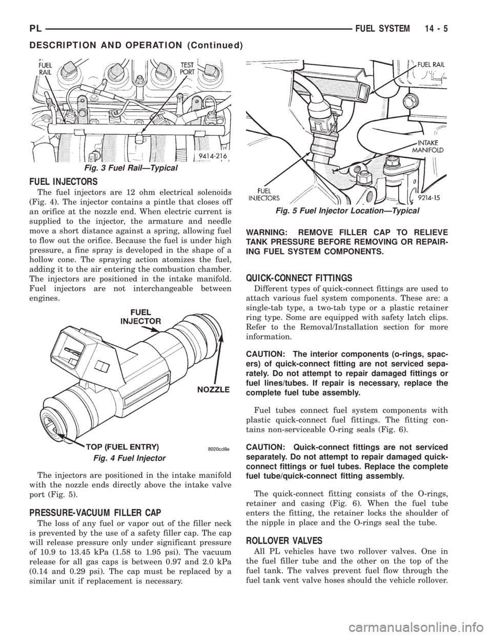
FUEL RAIL
The fuel rail supplies the necessary fuel to each
individual fuel injector and is mounted to the intake
manifold (Fig. 3). The fuel pressure regulator is no
longer mounted to the fuel rail on any engine. It is
now located on the fuel tank mounted fuel pump
module. Refer to Fuel Filter/Fuel Pressure Regulator
in the Fuel Delivery System section of this group for
information. The fuel rail is not repairable.
Fig. 2 Side ViewÐFilter/Regulator
14 - 4 FUEL SYSTEMPL
DESCRIPTION AND OPERATION (Continued)
Page 846 of 1200
FUEL INJECTORS
The fuel injectors are 12 ohm electrical solenoids
(Fig. 4). The injector contains a pintle that closes off
an orifice at the nozzle end. When electric current is
supplied to the injector, the armature and needle
move a short distance against a spring, allowing fuel
to flow out the orifice. Because the fuel is under high
pressure, a fine spray is developed in the shape of a
hollow cone. The spraying action atomizes the fuel,
adding it to the air entering the combustion chamber.
The injectors are positioned in the intake manifold.
Fuel injectors are not interchangeable between
engines.
The injectors are positioned in the intake manifold
with the nozzle ends directly above the intake valve
port (Fig. 5).
PRESSURE-VACUUM FILLER CAP
The loss of any fuel or vapor out of the filler neck
is prevented by the use of a safety filler cap. The cap
will release pressure only under significant pressure
of 10.9 to 13.45 kPa (1.58 to 1.95 psi). The vacuum
release for all gas caps is between 0.97 and 2.0 kPa
(0.14 and 0.29 psi). The cap must be replaced by a
similar unit if replacement is necessary.WARNING: REMOVE FILLER CAP TO RELIEVE
TANK PRESSURE BEFORE REMOVING OR REPAIR-
ING FUEL SYSTEM COMPONENTS.
QUICK-CONNECT FITTINGS
Different types of quick-connect fittings are used to
attach various fuel system components. These are: a
single-tab type, a two-tab type or a plastic retainer
ring type. Some are equipped with safety latch clips.
Refer to the Removal/Installation section for more
information.
CAUTION: The interior components (o-rings, spac-
ers) of quick-connect fitting are not serviced sepa-
rately. Do not attempt to repair damaged fittings or
fuel lines/tubes. If repair is necessary, replace the
complete fuel tube assembly.
Fuel tubes connect fuel system components with
plastic quick-connect fuel fittings. The fitting con-
tains non-serviceable O-ring seals (Fig. 6).
CAUTION: Quick-connect fittings are not serviced
separately. Do not attempt to repair damaged quick-
connect fittings or fuel tubes. Replace the complete
fuel tube/quick-connect fitting assembly.
The quick-connect fitting consists of the O-rings,
retainer and casing (Fig. 6). When the fuel tube
enters the fitting, the retainer locks the shoulder of
the nipple in place and the O-rings seal the tube.
ROLLOVER VALVES
All PL vehicles have two rollover valves. One in
the fuel filler tube and the other on the top of the
fuel tank. The valves prevent fuel flow through the
fuel tank vent valve hoses should the vehicle rollover.
Fig. 3 Fuel RailÐTypical
Fig. 4 Fuel Injector
Fig. 5 Fuel Injector LocationÐTypical
PLFUEL SYSTEM 14 - 5
DESCRIPTION AND OPERATION (Continued)