1999 DODGE NEON ECU
[x] Cancel search: ECUPage 9 of 1200
DISCONNECT CABLE CLAMPS AS FOLLOWS:
²Disconnect BLACK cable clamp from engine
ground on disabled vehicle.
²When using a Booster vehicle, disconnect
BLACK cable clamp from battery negative terminal.
Disconnect RED cable clamp from battery positive
terminal.
²Disconnect RED cable clamp from battery posi-
tive terminal on disabled vehicle.
TOWING RECOMMENDATIONS
WARNING: DO NOT ALLOW TOWING ATTACH-
MENT DEVICES TO CONTACT THE FUEL TANK OR
LINES, FUEL LEAK CAN RESULT. DO NOT LIFT OR
TOW VEHICLE BY FRONT OR REAR BUMPER, OR
BUMPER ENERGY ABSORBER UNITS. DO NOT
VENTURE UNDER A LIFTED VEHICLE IF NOT SUP-
PORTED PROPERLY ON SAFETY STANDS. DO NOT
ALLOW PASSENGERS TO RIDE IN A TOWED VEHI-
CLE. USE A SAFETY CHAIN THAT IS INDEPENDENT
FROM THE TOWING ATTACHMENT DEVICE.
CAUTION: Do not damage brake lines, exhaust
system, shock absorbers, sway bars, or any other
under vehicle components when attaching towing
device to vehicle. Do not attach towing device to
front or rear suspension components. Do not
secure vehicle to towing device by the use of front
or rear suspension or steering components.
Remove or secure loose or protruding objects from
a damaged vehicle before towing. Refer to state and
local rules and regulations before towing a vehicle.
Do not allow weight of towed vehicle to bear on
lower fascia, air dams, or spoilers.
RECOMMENDED TOWING EQUIPMENT
To avoid damage to bumper fascia and air dams
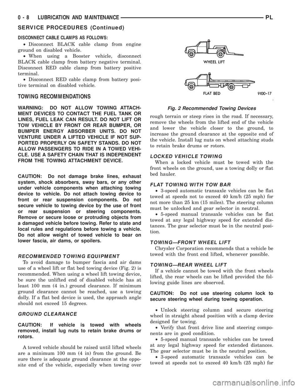
use of a wheel lift or flat bed towing device (Fig. 2) is
recommended. When using a wheel lift towing device,
be sure the unlifted end of disabled vehicle has at
least 100 mm (4 in.) ground clearance. If minimum
ground clearance cannot be reached, use a towing
dolly. If a flat bed device is used, the approach angle
should not exceed 15 degrees.
GROUND CLEARANCE
CAUTION: If vehicle is towed with wheels
removed, install lug nuts to retain brake drums or
rotors.
A towed vehicle should be raised until lifted wheels
are a minimum 100 mm (4 in) from the ground. Be
sure there is adequate ground clearance at the oppo-
site end of the vehicle, especially when towing overrough terrain or steep rises in the road. If necessary,
remove the wheels from the lifted end of the vehicle
and lower the vehicle closer to the ground, to
increase the ground clearance at the opposite end of
the vehicle. Install lug nuts on wheel attaching studs
to retain brake drums or rotors.
LOCKED VEHICLE TOWING
When a locked vehicle must be towed with the
front wheels on the ground, use a towing dolly or flat
bed hauler.
FLAT TOWING WITH TOW BAR
²3-speed automatic transaxle vehicles can be flat
towed at speeds not to exceed 40 km/h (25 mph) for
not more than 25 km (15 miles). The steering column
must be unlocked and gear selector in neutral.
²5-speed manual transaxle vehicles can be flat
towed at any legal highway speed for extended dis-
tances. The gear selector must be in the neutral posi-
tion.
TOWINGÐFRONT WHEEL LIFT
Chrysler Corporation recommends that a vehicle be
towed with the front end lifted, whenever possible.
TOWINGÐREAR WHEEL LIFT
If a vehicle cannot be towed with the front wheels
lifted, the rear wheels can be lifted provided the fol-
lowing guide lines are observed.
CAUTION: Do not use steering column lock to
secure steering wheel during towing operation.
²Unlock steering column and secure steering
wheel in straight ahead position with a clamp device
designed for towing.
²Verify that front drive line and steering compo-
nents are in good condition.
²5-speed manual transaxle vehicles can be towed
at any legal highway speed for extended distances.
The gear selector must be in the neutral position.
²3-speed automatic transaxle vehicles can be
towed at speeds not to exceed 40 km/h (25 mph) for
Fig. 2 Recommended Towing Devices
0 - 8 LUBRICATION AND MAINTENANCEPL
SERVICE PROCEDURES (Continued)
Page 10 of 1200

not more than 25 km (15 miles). The gear selector
must be in the neutral position.
HOISTING RECOMMENDATIONS
Refer to Owner's Manual provided with vehicle for
proper emergency jacking procedures.
WARNING: THE HOISTING AND JACK LIFTING
POINTS PROVIDED ARE FOR A COMPLETE VEHI-
CLE. WHEN THE ENGINE OR REAR SUSPENSION
IS REMOVED FROM A VEHICLE, THE CENTER OF
GRAVITY IS ALTERED MAKING SOME HOISTING
CONDITIONS UNSTABLE. PROPERLY SUPPORT OR
SECURE VEHICLE TO HOISTING DEVICE WHEN
THESE CONDITIONS EXIST.
CAUTION: Do not position hoisting device on sus-
pension components, damage to vehicle can result.
Do not attempt to raise one entire side of the
vehicle by placing a floor jack midway between the
front and rear wheels. This practice may result in
permanent damage to the body.
FLOOR JACK
When properly positioned, a floor jack can be used
to lift a PL vehicle (Fig. 3). Support the vehicle in the
raised position with jack stands.
A floor jack must never be used on any part of the
underbody.
HOIST
A vehicle can be lifted with:
²A single-post, frame-contact hoist.²A twin-post, chassis hoist.
²A ramp-type, drive-on hoist.
NOTE: When a frame-contact type hoist is used,
verify that the lifting pads are positioned properly
(Fig. 3).
Fig. 3 Hoisting and Jacking Points
PLLUBRICATION AND MAINTENANCE 0 - 9
SERVICE PROCEDURES (Continued)
Page 17 of 1200
CAMBER ADJUSTMENT BOLT PACKAGE INSTALLATION
PROCEDURE
(1) If front and or rear camber readings obtained
are not within the required specification range, a
Mopar Service Kit is available to provide the
required adjustment. The kit contains new bolts and
nuts for the strut clevis bracket to steering knuckle
attachment. The bolts contained in the service kit,
are slightly undersize allowing for movement
between the strut clevis bracket and steering
knuckle. The movement allowed by the undersize
bolts will provide approximately 2 degrees of camber
adjustment per side of vehicle. To install new bolts in
service kit follow the procedure below.
CAUTION: The Mopar Service Kit for allowing
adjustment of front and rear camber are different
for the front and rear of the vehicle. When using the
service kits be sure that the front and rear strut
attaching bolts are always used in the right location
on the vehicle.
(2) Raise front and or rear of vehicle until tires are
not supporting the weight of the vehicle.
CAUTION: The steering knuckle and rear knuckle
to strut assembly attaching bolts are serrated and
must not be turned during removal. Remove nuts
while holding bolts stationary in the steering knuck-
les.
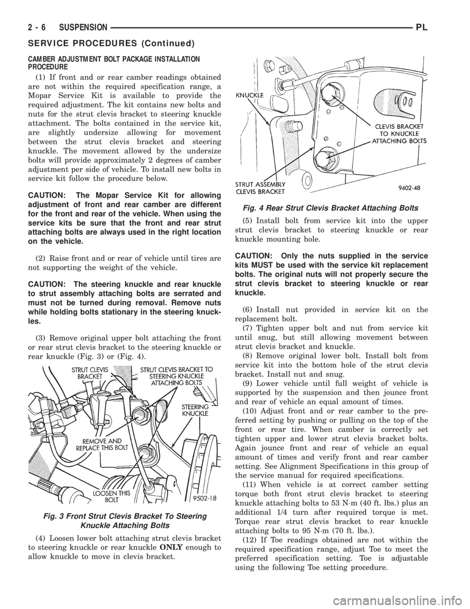
(3) Remove original upper bolt attaching the front
or rear strut clevis bracket to the steering knuckle or
rear knuckle (Fig. 3) or (Fig. 4).
(4) Loosen lower bolt attaching strut clevis bracket
to steering knuckle or rear knuckleONLYenough to
allow knuckle to move in clevis bracket.(5) Install bolt from service kit into the upper
strut clevis bracket to steering knuckle or rear
knuckle mounting hole.
CAUTION: Only the nuts supplied in the service
kits MUST be used with the service kit replacement
bolts. The original nuts will not properly secure the
strut clevis bracket to steering knuckle or rear
knuckle.
(6) Install nut provided in service kit on the
replacement bolt.
(7) Tighten upper bolt and nut from service kit
until snug, but still allowing movement between
strut clevis bracket and knuckle.
(8) Remove original lower bolt. Install bolt from
service kit into the bottom hole of the strut clevis
bracket. Install nut and snug.
(9) Lower vehicle until full weight of vehicle is
supported by the suspension and then jounce front
and rear of vehicle an equal amount of times.
(10) Adjust front and or rear camber to the pre-
ferred setting by pushing or pulling on the top of the
front or rear tire. When camber is correctly set
tighten upper and lower strut clevis bracket bolts.
Again jounce front and rear of vehicle an equal
amount of times and verify front and rear camber
setting. See Alignment Specifications in this group of
the service manual for required specifications.
(11) When vehicle is at correct camber setting
torque both front strut clevis bracket to steering
knuckle attaching bolts to 53 N´m (40 ft. lbs.) plus an
additional 1/4 turn after required torque is met.
Torque rear strut clevis bracket to rear knuckle
attaching bolts to 95 N´m (70 ft. lbs.).
(12) If Toe readings obtained are not within the
required specification range, adjust Toe to meet the
preferred specification setting. Toe is adjustable
using the following Toe setting procedure.
Fig. 3 Front Strut Clevis Bracket To Steering
Knuckle Attaching Bolts
Fig. 4 Rear Strut Clevis Bracket Attaching Bolts
2 - 6 SUSPENSIONPL
SERVICE PROCEDURES (Continued)
Page 19 of 1200
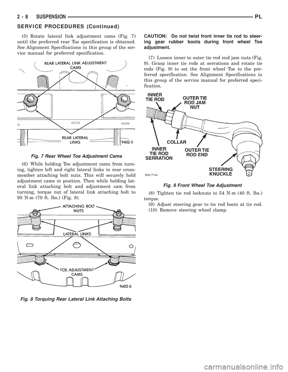
(5) Rotate lateral link adjustment cams (Fig. 7)
until the preferred rear Toe specification is obtained.
See Alignment Specifications in this group of the ser-
vice manual for preferred specification.
(6) While holding Toe adjustment cams from turn-
ing, tighten left and right lateral links to rear cross-
member attaching bolt nuts. This will securely hold
adjustment cams in position. Then while holding lat-
eral link attaching bolt and adjustment cam from
turning, torque nut of lateral link attaching bolt to
95 N´m (70 ft. lbs.) (Fig. 8).CAUTION: Do not twist front inner tie rod to steer-
ing gear rubber boots during front wheel Toe
adjustment.
(7) Loosen inner to outer tie rod end jam nuts (Fig.
9). Grasp inner tie rods at serrations and rotate tie
rods (Fig. 9) to set the front wheel Toe to the pre-
ferred specification. See Alignment Specifications in
this group of the service manual for preferred speci-
fication.
(8) Tighten tie rod locknuts to 54 N´m (40 ft. lbs.)
torque.
(9) Adjust steering gear to tie rod boots at tie rod.
(10) Remove steering wheel clamp.
Fig. 7 Rear Wheel Toe Adjustment Cams
Fig. 8 Torquing Rear Lateral Link Attaching Bolts
Fig. 9 Front Wheel Toe Adjustment
2 - 8 SUSPENSIONPL
SERVICE PROCEDURES (Continued)
Page 55 of 1200

(7) Remove carpet (if required) from top of strut
tower. Then remove rubber dust shield (Fig. 8) from
top of strut tower, this will allow easier access to
upper strut mount attaching nuts.
(8) Loosen but do not remove the 4 upper strut
mount to strut tower attaching nuts (Fig. 9). Then
while supporting the strut assembly fully remove the
4 strut mount attaching nuts.
(9) Remove strut assembly from knuckle, by slid-
ing knuckle out of clevis bracket on strut assembly.
Then remove strut assembly from vehicle.
INSTALL
(1) Position strut assembly back into vehicle with
the 4 studs on strut mount assembly through holes
in strut tower of vehicle. Install the 4 strut mount to
body attaching nuts (Fig. 9) onto mount studs.
Torque the 4 strut mount to body attaching nuts to
34 N´m (300 in. lbs).(2) Install dust shield into hole on top of strut
tower (Fig. 8). Install carpeting back on top of rear
strut tower.
(3) Raise vehicle.
CAUTION: The knuckle to strut assembly attaching
bolts are serrated and must not be turned during
installation. Install and torque nuts while holding
bolts stationary in knuckle.
(4) Install knuckle assembly into clevis bracket on
strut assembly. Install the 2 clevis bracket to knuckle
assembly attaching bolts and nuts (Fig. 7). Torque
both clevis bracket to knuckle assembly attaching
nuts to 95 N´m (70 ft. lbs.).
(5) Install hydraulic flex hose bracket, on strut
assembly bracket (Fig. 6). Install and securely
tighten bolt attaching hose bracket to strut bracket.
If vehicle is equipped with Anti-Lock brakes, the
wheel speed sensor cable routing clip is also attached
to the strut assembly bracket.
(6) Install wheel and tire assembly on vehicle.
Tighten the wheel mounting stud nuts in proper
sequence until all nuts are torqued to half specifica-
tion. Then repeat tightening sequence to full speci-
fied torque of 135 N´m (100 ft. lbs.).
(7) Lower vehicle to the ground.
(8) Check and reset rear wheel TOE to specifica-
tions if required. Refer to Front And Rear Toe Setting
Procedure in the Wheel Alignment Check And
Adjustment section in this group of the service man-
ual for the required Toe setting procedure.
COIL SPRING
Coil springs are rated separately for each side of
vehicle depending on optional equipment and type of
service. During service procedures where both
springs are removed, mark springs (Chalk, Tape,
etc.) (Fig. 10) to ensure installation in original posi-
tion. If the coils springs require replacement.Be
sure that the springs needing replacement, are
replaced with springs meeting the correct load
and spring rate for the vehicle.
NOTE: During service procedures requiring
removal or installation of a coil spring with Spring
Compressor, Special Tool C-4838. It is required that
the first full top and bottom coil of the coil spring
be captured by the jaws of spring compressor (Fig.
10).
Replacement of the coil spring requires removal of
the strut assembly from the vehicle, and the disas-
sembly of the strut. Refer to strut assembly in the
removal and installation section in this group of the
service manual for the required removal and replace-
ment procedure for the strut assembly. Then refer to
Fig. 8 Dust Shield Removal From Strut Tower
Fig. 9 Strut Mount Attaching Nuts
2 - 44 SUSPENSIONPL
REMOVAL AND INSTALLATION (Continued)
Page 56 of 1200
strut assembly in the disassembly and assembly sec-
tion in this group of the service manual for the
required procedure to disassemble and assemble the
strut assembly for the removal of the coil spring.
STABILIZER BAR
REMOVE
(1) Raise vehicle on jackstands or centered on a
frame contact type hoist. See Hoisting in the Lubri-
cation and Maintenance section of this manual, for
the required lifting procedure to be used for this
vehicle.
(2) Remove both rear wheel and tire assemblies
from the vehicle.
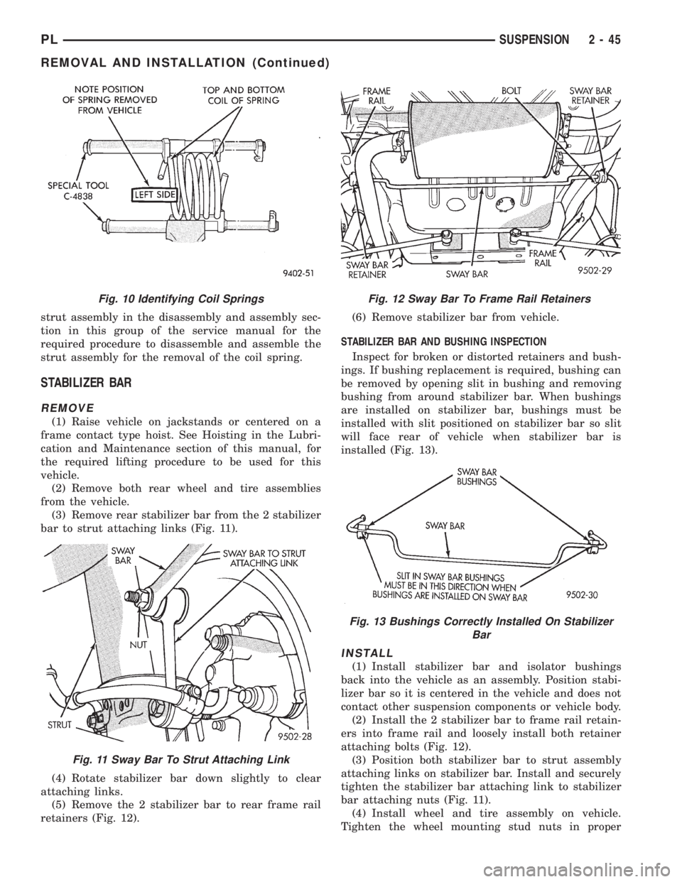
(3) Remove rear stabilizer bar from the 2 stabilizer
bar to strut attaching links (Fig. 11).
(4) Rotate stabilizer bar down slightly to clear
attaching links.
(5) Remove the 2 stabilizer bar to rear frame rail
retainers (Fig. 12).(6) Remove stabilizer bar from vehicle.
STABILIZER BAR AND BUSHING INSPECTION
Inspect for broken or distorted retainers and bush-
ings. If bushing replacement is required, bushing can
be removed by opening slit in bushing and removing
bushing from around stabilizer bar. When bushings
are installed on stabilizer bar, bushings must be
installed with slit positioned on stabilizer bar so slit
will face rear of vehicle when stabilizer bar is
installed (Fig. 13).
INSTALL
(1) Install stabilizer bar and isolator bushings
back into the vehicle as an assembly. Position stabi-
lizer bar so it is centered in the vehicle and does not
contact other suspension components or vehicle body.
(2) Install the 2 stabilizer bar to frame rail retain-
ers into frame rail and loosely install both retainer
attaching bolts (Fig. 12).
(3) Position both stabilizer bar to strut assembly
attaching links on stabilizer bar. Install and securely
tighten the stabilizer bar attaching link to stabilizer
bar attaching nuts (Fig. 11).
(4) Install wheel and tire assembly on vehicle.
Tighten the wheel mounting stud nuts in proper
Fig. 10 Identifying Coil Springs
Fig. 11 Sway Bar To Strut Attaching Link
Fig. 12 Sway Bar To Frame Rail Retainers
Fig. 13 Bushings Correctly Installed On Stabilizer
Bar
PLSUSPENSION 2 - 45
REMOVAL AND INSTALLATION (Continued)
Page 57 of 1200

sequence until all nuts are torqued to half specifica-
tion. Then repeat the tightening sequence to the full
specified torque of 129 N´m (95 ft. lbs.).
(5) Lower the vehicle to the ground.
(6) With suspension supporting the full weight of
the vehicle, securely tighten the stabilizer bar
retainer to frame rail attaching bolts (Fig. 11).
KNUCKLE
REMOVE
(1) Raise vehicle on jackstands or centered on a
frame contact type hoist. See Hoisting in the Lubri-
cation and Maintenance section of this manual, for
the required lifting procedure to be used for this
vehicle.
(2) Remove the rear wheel and tire.
(3) If vehicle is equipped with rear disc brakes,
remove the rear caliper from the adapter. Refer to
Rear Disk Brakes in Group 5 Brakes of this Service
manual for required caliper removal procedure. After
removing the caliper, store the caliper by hanging it
from frame of the vehicle (Fig. 14). Do not let weight
of rear caliper hang from flexible brake hose.
(4) If vehicle is equipped with rear disc brakes,
remove rotor from hub. If vehicle is equipped with
rear drum brakes, remove brake drum from hub.
(5) If vehicle is equipped with ABS brakes, remove
wheel speed sensor from rear disc brake adapter
(Fig. 15).
(6) Remove rear hub/bearing retaining nut (Fig.
16). Then remove the hub/bearing from the knuckle.(7) If vehicle is equipped with rear drum brakes
remove the 4 bolts (Fig. 17) attaching rear brake sup-
port plate to knuckle. Then remove brake support
plate, brake shoes and wheel cylinder as an assembly
from rear knuckle (Fig. 17).It is not necessary to
remove brake flex hose from wheel cylinder
when removing support plate.Brake support
plate when removed, must be supported in same
manner as caliper assembly.
(8) On vehicles equipped with rear disc brakes,
remove the 4 bolts attaching disc brake adapter to
rear knuckle (Fig. 18). Then remove the adapter,
rotor shield, park brake shoes and park brake cable
as an assembly from knuckle.
CAUTION: The knuckle to strut assembly attaching
bolts are serrated and must not be turned during
removal. Loosen and remove nuts while holding
bolts stationary in knuckle.
Fig. 14 Storing Rear Caliper
Fig. 15 Speed Sensor Head Attachment To Disc
Brake Adapter
Fig. 16 Hub/ Bearing Retaining Nut
2 - 46 SUSPENSIONPL
REMOVAL AND INSTALLATION (Continued)
Page 67 of 1200
the jounce and rebound travel of the front suspen-
sion.
On vehicles equipped with ABS brakes, the outer
C/V joint is equipped with a tone wheel used to
determine vehicle speed for ABS brake operation.
The inner tripod joint of both driveshafts is splined
into the transaxle side gears. The inner tripod joints
are retained in the side gears of the transaxle using
a snap ring located in the stub shaft of the tripod
joint. The outer C/V joint has a stub shaft that is
splined into the wheel hub and retained by a hub nut
using a nut lock and cotter pin.
NOTE: This vehicle does not use a rubber±lip bear-
ing seal as on previous front±wheel±drive cars to
prevent contamination of the front wheel bearing.
On these vehicles, the face of the outer C/V joint
fits deeply into the steering knuckle, using a close
outer C/V joint±to±steering knuckle fit. This design
deters direct water splash on bearing seal while
allowing any water that gets in, to run out the bot-
tom of the steering knuckle bearing bore. It is
important to thoroughly clean the outer C/V joint
and the wheel bearing area in the steering knuckle
before it is assembled after servicing.
DIAGNOSIS AND TESTING
DRIVESHAFT DIAGNOSIS
VEHICLE INSPECTION
(1) Check for grease in the vicinity of the inboard
tripod joint and outboard C/V joint; this is a sign of
inner or outer joint seal boot or seal boot clamp dam-
age.
(2) A light film of grease may appear on the right
inner tripod joint seal boot; this is considered normal
and should not require replacement of the seal boot.
The right inner tripod joint seal boot is made of sili-
cone rubber; which will allow the weeping (sweating)
of the joint lubricant to pass through it while in oper-
ation.
NOISE AND/OR VIBRATION IN TURNS
A clicking noise and/or a vibration in turns could
be caused by one of the following conditions.
(1) Damaged outer C/V or inner tripod joint seal
boot or seal boot clamps. This will result in the loss
and/or contamination of the joint grease, resulting in
inadequate lubrication of the joint.
(2) Noise may also be caused by another compo-
nent of the vehicle coming in contact with the drive-
shafts.
CLUNKING NOISE DURING ACCELERATION
This noise may be a result of one of the following
conditions:
(1) A torn seal boot on the inner or outer joint of
the driveshaft assembly.
(2) A loose or missing clamp on the inner or outer
joint of the driveshaft assembly.
(3) A damaged or worn driveshaft C/V joint.
SHUDDER OR VIBRATION DURING
ACCELERATION
(1) A worn or damaged driveshaft inner tripod
joint.
(2) A sticking tripod joint spider assembly (inner
tripod joint only).
(3) Improper wheel alignment. See Wheel Align-
ment in this group for alignment checking and set-
ting procedures and specifications.
VIBRATION AT HIGHWAY SPEEDS
(1) Foreign material (mud, etc.) packed on the
backside of the wheel(s).
(2) Out of balance front tires or wheels. See Group
22, Wheels And Tires for the required balancing pro-
cedure.
(3) Improper tire and/or wheel runout. See Group
22, Wheels And Tires for the required runout check-
ing procedure.
REMOVAL AND INSTALLATION
FRONT DRIVESHAFTS
CAUTION: Boot sealing is vital to retain special
lubricants and to prevent foreign contaminants
from entering the C/V joint. Mishandling, such as
allowing the assemblies to dangle unsupported, or
pulling or pushing the ends can cut boots or dam-
age C/V joints. During removal and installation pro-
cedures, always support both ends of the driveshaft
to prevent damage.
REMOVAL
CAUTION: The driveshaft, when installed, acts as a
bolt and secures the front hub/bearing assembly. If
vehicle is to be supported or moved on its wheels
with a driveshaft removed, install a PROPER±SIZED
BOLT AND NUT through front hub. Tighten bolt and
nut to 203 N´m (150 ft. lbs.). This will ensure that
the hub bearing cannot loosen.
(1) Remove cotter pin, nut lock, and spring washer
(Fig. 2) from the end of the outer C/V joint stub axle.
(2) Loosen (but do not remove) stub axle±to±hub/
bearing retaining nut (Fig. 3). Loosen hub nut while
3 - 2 DIFFERENTIAL AND DRIVELINEPL
GENERAL INFORMATION (Continued)