1999 DODGE NEON fuel pressure
[x] Cancel search: fuel pressurePage 889 of 1200
at about 20mVac (at about 700 rpm) and increases to
approximately 600 mVac (5000 rpm). If the output falls
outside of this range a DTC will be set.
MANIFOLD ABSOLUTE PRESSURE (MAP) SENSOR
To perform a complete test of the MAP sensor and
its circuitry, refer to the DRB scan tool and appropri-
ate Powertrain Diagnostics Procedures manual. To
test the MAP sensor only, refer to the following:
CAUTION: When testing the MAP sensor, be sure
that the harness wires are not damaged by the test
meter probes.
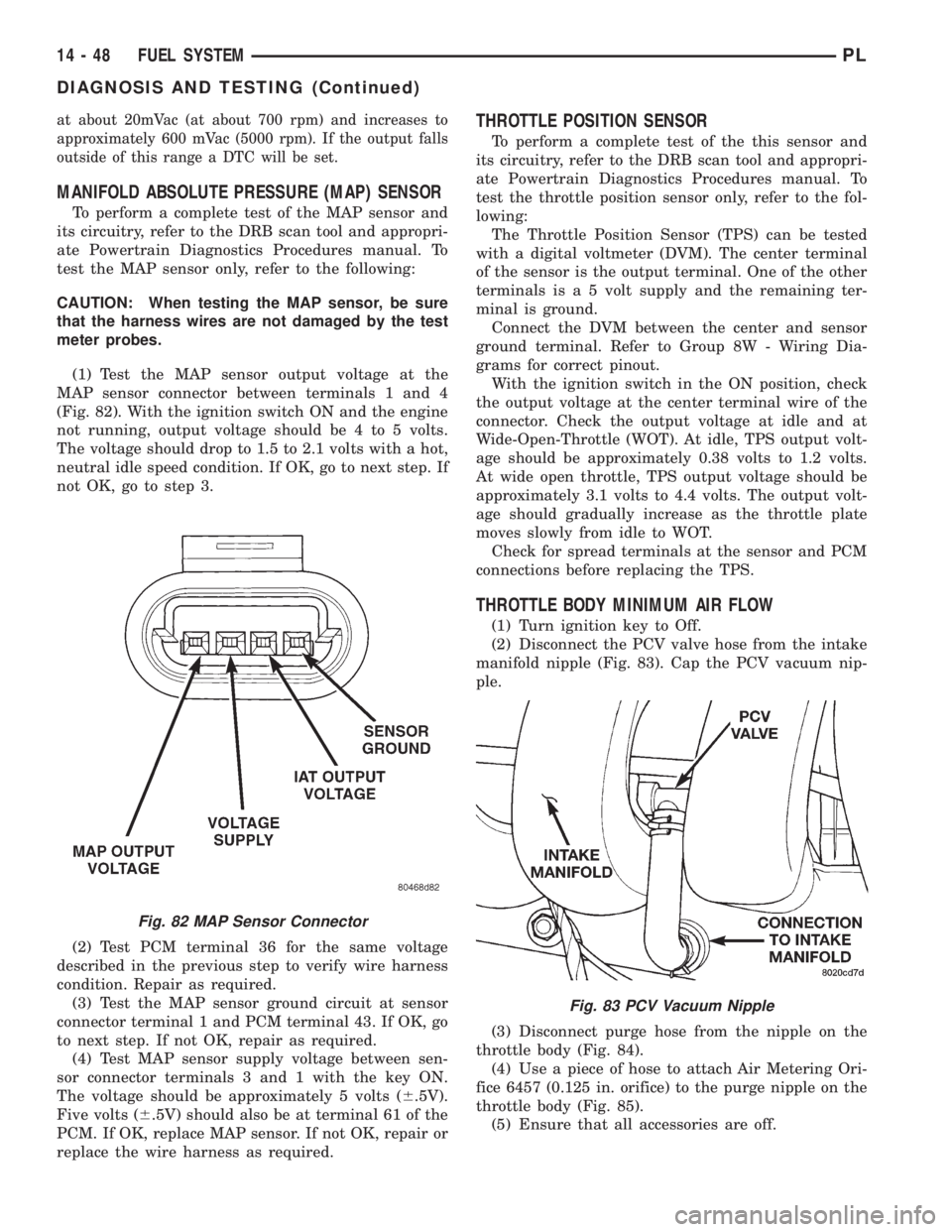
(1) Test the MAP sensor output voltage at the
MAP sensor connector between terminals 1 and 4
(Fig. 82). With the ignition switch ON and the engine
not running, output voltage should be 4 to 5 volts.
The voltage should drop to 1.5 to 2.1 volts with a hot,
neutral idle speed condition. If OK, go to next step. If
not OK, go to step 3.
(2) Test PCM terminal 36 for the same voltage
described in the previous step to verify wire harness
condition. Repair as required.
(3) Test the MAP sensor ground circuit at sensor
connector terminal 1 and PCM terminal 43. If OK, go
to next step. If not OK, repair as required.
(4) Test MAP sensor supply voltage between sen-
sor connector terminals 3 and 1 with the key ON.
The voltage should be approximately 5 volts (6.5V).
Five volts (6.5V) should also be at terminal 61 of the
PCM. If OK, replace MAP sensor. If not OK, repair or
replace the wire harness as required.
THROTTLE POSITION SENSOR
To perform a complete test of the this sensor and
its circuitry, refer to the DRB scan tool and appropri-
ate Powertrain Diagnostics Procedures manual. To
test the throttle position sensor only, refer to the fol-
lowing:
The Throttle Position Sensor (TPS) can be tested
with a digital voltmeter (DVM). The center terminal
of the sensor is the output terminal. One of the other
terminals is a 5 volt supply and the remaining ter-
minal is ground.
Connect the DVM between the center and sensor
ground terminal. Refer to Group 8W - Wiring Dia-
grams for correct pinout.
With the ignition switch in the ON position, check
the output voltage at the center terminal wire of the
connector. Check the output voltage at idle and at
Wide-Open-Throttle (WOT). At idle, TPS output volt-
age should be approximately 0.38 volts to 1.2 volts.
At wide open throttle, TPS output voltage should be
approximately 3.1 volts to 4.4 volts. The output volt-
age should gradually increase as the throttle plate
moves slowly from idle to WOT.
Check for spread terminals at the sensor and PCM
connections before replacing the TPS.
THROTTLE BODY MINIMUM AIR FLOW
(1) Turn ignition key to Off.
(2) Disconnect the PCV valve hose from the intake
manifold nipple (Fig. 83). Cap the PCV vacuum nip-
ple.
(3) Disconnect purge hose from the nipple on the
throttle body (Fig. 84).
(4) Use a piece of hose to attach Air Metering Ori-
fice 6457 (0.125 in. orifice) to the purge nipple on the
throttle body (Fig. 85).
(5) Ensure that all accessories are off.
Fig. 82 MAP Sensor Connector
Fig. 83 PCV Vacuum Nipple
14 - 48 FUEL SYSTEMPL
DIAGNOSIS AND TESTING (Continued)
Page 891 of 1200
REMOVAL AND INSTALLATION
THROTTLE BODYÐMANUAL TRANSMISSION
Remove throttle body cables using the following
procedures.
REMOVAL
(1) Remove throttle cable cover.
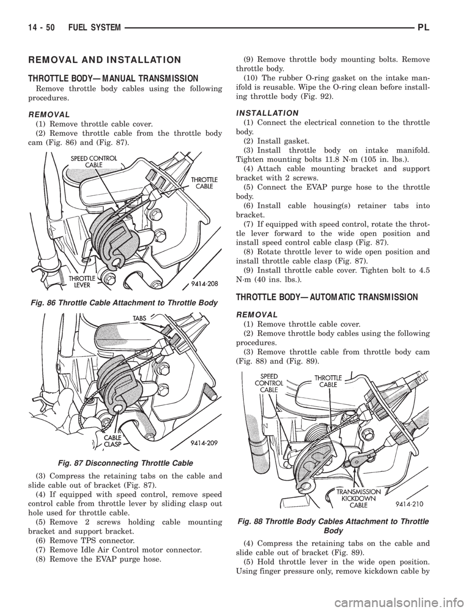
(2) Remove throttle cable from the throttle body
cam (Fig. 86) and (Fig. 87).
(3) Compress the retaining tabs on the cable and
slide cable out of bracket (Fig. 87).
(4) If equipped with speed control, remove speed
control cable from throttle lever by sliding clasp out
hole used for throttle cable.
(5) Remove 2 screws holding cable mounting
bracket and support bracket.
(6) Remove TPS connector.
(7) Remove Idle Air Control motor connector.
(8) Remove the EVAP purge hose.(9) Remove throttle body mounting bolts. Remove
throttle body.
(10) The rubber O-ring gasket on the intake man-
ifold is reusable. Wipe the O-ring clean before install-
ing throttle body (Fig. 92).
INSTALLATION
(1) Connect the electrical connetion to the throttle
body.
(2) Install gasket.
(3) Install throttle body on intake manifold.
Tighten mounting bolts 11.8 N´m (105 in. lbs.).
(4) Attach cable mounting bracket and support
bracket with 2 screws.
(5) Connect the EVAP purge hose to the throttle
body.
(6) Install cable housing(s) retainer tabs into
bracket.
(7) If equipped with speed control, rotate the throt-
tle lever forward to the wide open position and
install speed control cable clasp (Fig. 87).
(8) Rotate throttle lever to wide open position and
install throttle cable clasp (Fig. 87).
(9) Install throttle cable cover. Tighten bolt to 4.5
N´m (40 ins. lbs.).
THROTTLE BODYÐAUTOMATIC TRANSMISSION
REMOVAL
(1) Remove throttle cable cover.
(2) Remove throttle body cables using the following
procedures.
(3) Remove throttle cable from throttle body cam
(Fig. 88) and (Fig. 89).
(4) Compress the retaining tabs on the cable and
slide cable out of bracket (Fig. 89).
(5) Hold throttle lever in the wide open position.
Using finger pressure only, remove kickdown cable by
Fig. 86 Throttle Cable Attachment to Throttle Body
Fig. 87 Disconnecting Throttle Cable
Fig. 88 Throttle Body Cables Attachment to Throttle
Body
14 - 50 FUEL SYSTEMPL
Page 892 of 1200
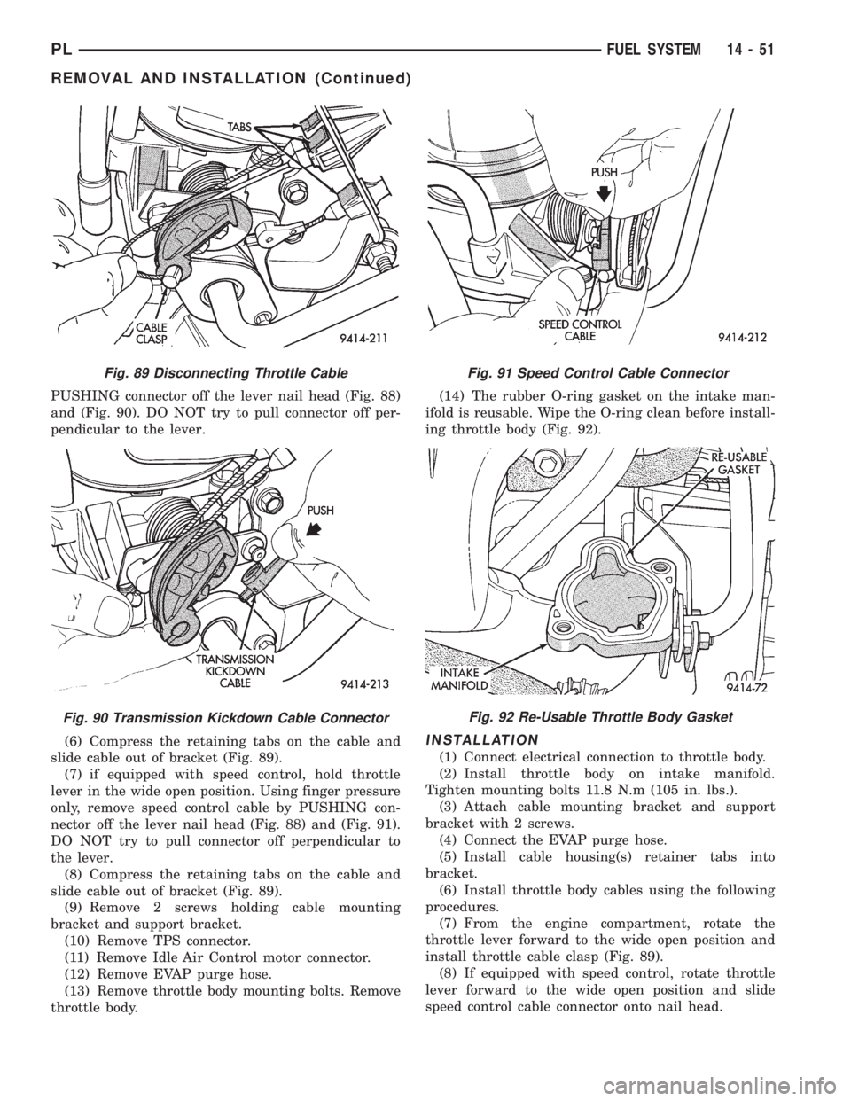
PUSHING connector off the lever nail head (Fig. 88)
and (Fig. 90). DO NOT try to pull connector off per-
pendicular to the lever.
(6) Compress the retaining tabs on the cable and
slide cable out of bracket (Fig. 89).
(7) if equipped with speed control, hold throttle
lever in the wide open position. Using finger pressure
only, remove speed control cable by PUSHING con-
nector off the lever nail head (Fig. 88) and (Fig. 91).
DO NOT try to pull connector off perpendicular to
the lever.
(8) Compress the retaining tabs on the cable and
slide cable out of bracket (Fig. 89).
(9) Remove 2 screws holding cable mounting
bracket and support bracket.
(10) Remove TPS connector.
(11) Remove Idle Air Control motor connector.
(12) Remove EVAP purge hose.
(13) Remove throttle body mounting bolts. Remove
throttle body.(14) The rubber O-ring gasket on the intake man-
ifold is reusable. Wipe the O-ring clean before install-
ing throttle body (Fig. 92).
INSTALLATION
(1) Connect electrical connection to throttle body.
(2) Install throttle body on intake manifold.
Tighten mounting bolts 11.8 N.m (105 in. lbs.).
(3) Attach cable mounting bracket and support
bracket with 2 screws.
(4) Connect the EVAP purge hose.
(5) Install cable housing(s) retainer tabs into
bracket.
(6) Install throttle body cables using the following
procedures.
(7) From the engine compartment, rotate the
throttle lever forward to the wide open position and
install throttle cable clasp (Fig. 89).
(8) If equipped with speed control, rotate throttle
lever forward to the wide open position and slide
speed control cable connector onto nail head.
Fig. 89 Disconnecting Throttle Cable
Fig. 90 Transmission Kickdown Cable Connector
Fig. 91 Speed Control Cable Connector
Fig. 92 Re-Usable Throttle Body Gasket
PLFUEL SYSTEM 14 - 51
REMOVAL AND INSTALLATION (Continued)
Page 898 of 1200

INSTALLATION
The speed sensor gear meshes with a gear on the
output shaft.
(1) With O-ring in place, install sensor.
(2) Install mounting bolt.
(3) Connect electrical connector to sensor.
KNOCK SENSOR
For removal/installation procedures refer to Group
8D- Ignition System, Service Procedures.
SPECIFICATIONS
VECI LABEL
If anything differs between the specifications found
on the Vehicle Emission Control Information (VECI)
label and the following specifications, use specifica-
tions on VECI label. The VECI label is located in the
engine compartment.
TORQUE
DESCRIPTION TORQUE
Air Cleaner Wingnut..........1.5 N´m (15 in. lbs.)
Air Cleaner Mount. Stud-To-Thrott. Body .10 N´m (90
in. lbs.)
Crankshaft Position Sensor Mounting Bolts.8 N´m (70
in. lbs.)
Engine Coolant Temperature Sensor .18 N´m (165 in.
lbs.)
IAC Motor-To-Throttle Body Bolts .7 N´m (60 in. lbs.)
MAP/IAT Sensor..............2N´m(20in.lbs.)
MAP/IAT Sensor..............3N´m(30in.lbs.)
Oxygen Sensor...............28N´m(20ft.lbs.)
Powertrain Control Module (PCM) Mounting Screws.4
N´m (35 in. lbs.)
Throttle Cable Cover.........4.5 N´m (40 in. lbs.).
Throttle Body Mounting Bolts . .23 N´m (200 in. lbs.)
Throttle Position Sensor Mounting Screws .2 N´m (20
in. lbs.)
Vehicle Speed Sensor Mounting Bolt .2.2 N´m (20 in.
lbs.)
SPECIAL TOOLS
FUEL
Fig. 108 Engine Coolant Temperature SensorÐ
DOHCFig. 109 Vehicle Speed Sensor
Extractor C±4334Pressure Gauge Assembly C±4799±B
PLFUEL SYSTEM 14 - 57
REMOVAL AND INSTALLATION (Continued)
Page 899 of 1200
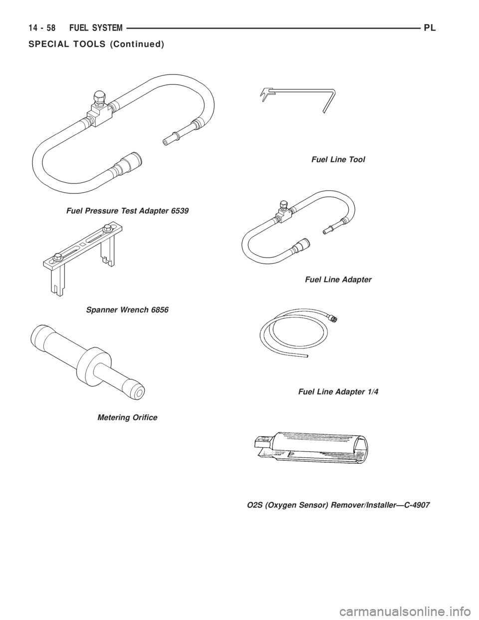
Fuel Pressure Test Adapter 6539
Spanner Wrench 6856
Metering Orifice
Fuel Line Tool
Fuel Line Adapter
Fuel Line Adapter 1/4
O2S (Oxygen Sensor) Remover/InstallerÐC-4907
14 - 58 FUEL SYSTEMPL
SPECIAL TOOLS (Continued)
Page 1069 of 1200
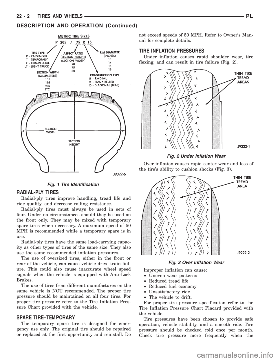
RADIAL-PLY TIRES
Radial-ply tires improve handling, tread life and
ride quality, and decrease rolling resistance.
Radial-ply tires must always be used in sets of
four. Under no circumstances should they be used on
the front only. They may be mixed with temporary
spare tires when necessary. A maximum speed of 50
MPH is recommended while a temporary spare is in
use.
Radial-ply tires have the same load-carrying capac-
ity as other types of tires of the same size. They also
use the same recommended inflation pressures.
The use of oversized tires, either in the front or
rear of the vehicle, can cause vehicle drive train fail-
ure. This could also cause inaccurate wheel speed
signals when the vehicle is equipped with Anti-Lock
Brakes.
The use of tires from different manufactures on the
same vehicle is NOT recommended. The proper tire
pressure should be maintained on all four tires. For
proper tire pressure refer to the Tire Inflation Pres-
sure Chart provided with the vehicle.
SPARE TIRE±TEMPORARY
The temporary spare tire is designed for emer-
gency use only. The original tire should be repaired
or replaced at the first opportunity and reinstall. Donot exceed speeds of 50 MPH. Refer to Owner's Man-
ual for complete details.
TIRE INFLATION PRESSURES
Under inflation causes rapid shoulder wear, tire
flexing, and can result in tire failure (Fig. 2).
Over inflation causes rapid center wear and loss of
the tire's ability to cushion shocks (Fig. 3).
Improper inflation can cause:
²Uneven wear patterns
²Reduced tread life
²Reduced fuel economy
²Unsatisfactory ride
²The vehicle to drift.
For proper tire pressure specification refer to the
Tire Inflation Pressure Chart Placard provided with
the vehicle.
Tire pressures have been chosen to provide safe
operation, vehicle stability, and a smooth ride. Tire
pressure should be checked cold once per month.
Check tire pressure more frequently when the
Fig. 1 Tire Identification
Fig. 2 Under Inflation Wear
Fig. 3 Over Inflation Wear
22 - 2 TIRES AND WHEELSPL
DESCRIPTION AND OPERATION (Continued)
Page 1167 of 1200
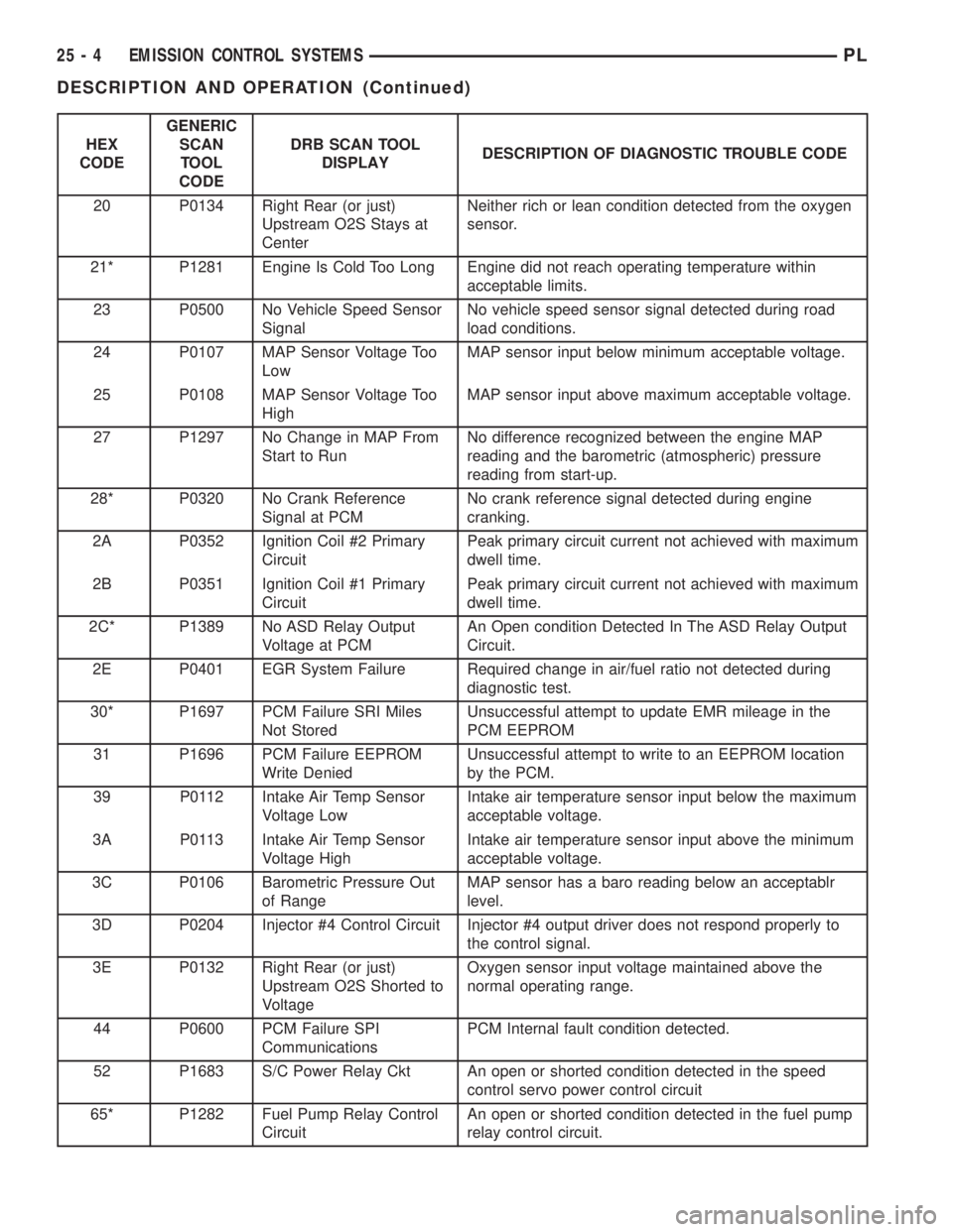
HEX
CODEGENERIC
SCAN
TOOL
CODEDRB SCAN TOOL
DISPLAYDESCRIPTION OF DIAGNOSTIC TROUBLE CODE
20 P0134 Right Rear (or just)
Upstream O2S Stays at
CenterNeither rich or lean condition detected from the oxygen
sensor.
21* P1281 Engine Is Cold Too Long Engine did not reach operating temperature within
acceptable limits.
23 P0500 No Vehicle Speed Sensor
SignalNo vehicle speed sensor signal detected during road
load conditions.
24 P0107 MAP Sensor Voltage Too
LowMAP sensor input below minimum acceptable voltage.
25 P0108 MAP Sensor Voltage Too
HighMAP sensor input above maximum acceptable voltage.
27 P1297 No Change in MAP From
Start to RunNo difference recognized between the engine MAP
reading and the barometric (atmospheric) pressure
reading from start-up.
28* P0320 No Crank Reference
Signal at PCMNo crank reference signal detected during engine
cranking.
2A P0352 Ignition Coil #2 Primary
CircuitPeak primary circuit current not achieved with maximum
dwell time.
2B P0351 Ignition Coil #1 Primary
CircuitPeak primary circuit current not achieved with maximum
dwell time.
2C* P1389 No ASD Relay Output
Voltage at PCMAn Open condition Detected In The ASD Relay Output
Circuit.
2E P0401 EGR System Failure Required change in air/fuel ratio not detected during
diagnostic test.
30* P1697 PCM Failure SRI Miles
Not StoredUnsuccessful attempt to update EMR mileage in the
PCM EEPROM
31 P1696 PCM Failure EEPROM
Write DeniedUnsuccessful attempt to write to an EEPROM location
by the PCM.
39 P0112 Intake Air Temp Sensor
Voltage LowIntake air temperature sensor input below the maximum
acceptable voltage.
3A P0113 Intake Air Temp Sensor
Voltage HighIntake air temperature sensor input above the minimum
acceptable voltage.
3C P0106 Barometric Pressure Out
of RangeMAP sensor has a baro reading below an acceptablr
level.
3D P0204 Injector #4 Control Circuit Injector #4 output driver does not respond properly to
the control signal.
3E P0132 Right Rear (or just)
Upstream O2S Shorted to
VoltageOxygen sensor input voltage maintained above the
normal operating range.
44 P0600 PCM Failure SPI
CommunicationsPCM Internal fault condition detected.
52 P1683 S/C Power Relay Ckt An open or shorted condition detected in the speed
control servo power control circuit
65* P1282 Fuel Pump Relay Control
CircuitAn open or shorted condition detected in the fuel pump
relay control circuit.
25 - 4 EMISSION CONTROL SYSTEMSPL
DESCRIPTION AND OPERATION (Continued)
Page 1168 of 1200
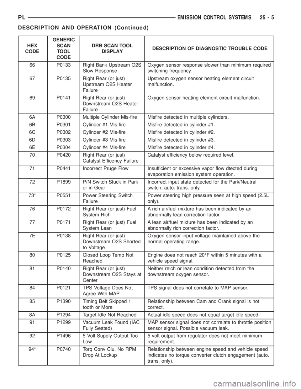
HEX
CODEGENERIC
SCAN
TOOL
CODEDRB SCAN TOOL
DISPLAYDESCRIPTION OF DIAGNOSTIC TROUBLE CODE
66 P0133 Right Bank Upstream O2S
Slow ResponseOxygen sensor response slower than minimum required
switching frequency.
67 P0135 Right Rear (or just)
Upstream O2S Heater
FailureUpstream oxygen sensor heating element circuit
malfunction.
69 P0141 Right Rear (or just)
Downstream O2S Heater
FailureOxygen sensor heating element circuit malfunction.
6A P0300 Multiple Cylinder Mis-fire Misfire detected in multiple cylinders.
6B P0301 Cylinder #1 Mis-fire Misfire detected in cylinder #1.
6C P0302 Cylinder #2 Mis-fire Misfire detected in cylinder #2.
6D P0303 Cylinder #3 Mis-fire Misfire detected in cylinder #3.
6E P0304 Cylinder #4 Mis-fire Misfire detected in cylinder #4.
70 P0420 Right Rear (or just)
Catalyst Efficency FailureCatalyst efficiency below required level.
71 P0441 Incorrect Pruge Flow Insufficient or excessive vapor flow dtected during
evaporation emission system operation.
72 P1899 P/N Switch Stuck in Park
or in GearIncorrect input state detected for the Park/Neutral
switch, auto. trans. only.
73* P0551 Power Steering Switch
FailurePower steering high pressure seen at high speed (2.5L
only).
76 P0172 Right Rear (or just) Fuel
System RichA rich air/fuel mixture has been indicated by an
abnormally lean correction factor.
77 P0171 Right Rear (or just) Fuel
System LeanA lean air/fuel mixture has been indicated by an
abnormally rich correction factor.
7E P0138 Right Rear (or just)
Downstream O2S Shorted
to VoltageOxygen sensor input voltage maintained above the
normal operating range.
80 P0125 Closed Loop Temp Not
ReachedEngine does not reach 20ÉF within 5 minutes with a
vehicle speed signal.
81 P0140 Right Rear (or just)
Downstream O2S Stays at
CenterNeither reich or lean condition detected from the
downstream oxygen sensor.
84 P0121 TPS Voltage Does Not
Agree With MAPTPS signal does not correlate to MAP sensor.
85 P1390 Timing Belt Skipped 1
tooth or MoreRelationship between Cam and Crank signal is not
correct.
8A P1294 Target Idle Not Reached Actual idle speed does not equal target idle speed.
91 P1299 Vacuum Leak Found (IAC
Fully Seated)MAP sensor signal does not correlate to throttle position
sensor signal. Possible vacuum leak.
92 P1496 5 Volt Supply Output Too
Low5 volt output from regulator does not meet minimum
requirement.
94* P0740 Torq Conv Clu, No RPM
Drop At LockupRelationship between engine speed and vehicle speed
indicates no torque converter clutch engagement (auto.
trans. only).
PLEMISSION CONTROL SYSTEMS 25 - 5
DESCRIPTION AND OPERATION (Continued)