1999 DODGE NEON fuel pressure
[x] Cancel search: fuel pressurePage 873 of 1200

disables the A/C compressor clutch for several sec-
onds.
The air conditioning clutch relay is located in the
PDC. The inside top of the PDC cover has a label
showing relay and fuse location.
AUTOMATIC SHUTDOWN RELAYÐPCM OUTPUT
The automatic shutdown (ASD) relay supplies bat-
tery voltage to the fuel injectors, electronic ignition
coil and the heating elements in the oxygen sensors.
A buss bar in the power distribution center (PDC)
supplies voltage to the solenoid side and contact side
of the relay. The ASD relay power circuit contains a
20 amp fuse between the buss bar in the PDC and
the relay. The fuse also protects the power circuit for
the fuel pump relay and pump. The fuse is located in
the PDC. Refer to Group 8W, Wiring Diagrams for
circuit information.
The PCM controls the relay by switching the
ground path for the solenoid side of the relay on and
off. The PCM turns the ground path off when the
ignition switch is in the Off position unless the 02
Heater Monitor test is being run. Refer to Group 25,
On-Board Diagnostics. When the ignition switch is in
the On or Crank position, the PCM monitors the
crankshaft position sensor and camshaft position sen-
sor signals to determine engine speed and ignition
timing (coil dwell). If the PCM does not receive the
crankshaft position sensor and camshaft position sen-
sor signals when the ignition switch is in the Run
position, it will de- energize the ASD relay.
The ASD relay is located in the PDC. The inside
top of the PDC cover has a label showing relay and
fuse location.
CHARGING SYSTEM INDICATOR LAMPÐPCM
OUTPUT
The PCM turns the instrument panel Charging
System Lamp on. Refer to Group 8C for charging sys-
tem information.
FUEL PUMP RELAYÐPCM OUTPUT
The fuel pump relay supplies battery voltage to the
fuel pump. A buss bar in the Power Distribution Cen-
ter (PDC) supplies voltage to the solenoid side and
contact side of the relay. The fuel pump relay power
circuit contains a 20 amp fuse between the buss bar
in the PDC and the relay. The fuse also protects the
power circuit for the Automatic Shutdown (ASD)
relay. The fuse is located in the PDC. Refer to Group
8W, Wiring Diagrams for circuit information.
The PCM controls the fuel pump relay by switch-
ing the ground path for the solenoid side of the relay
on and off. The PCM turns the ground path off when
the ignition switch is in the Off position. When the
ignition switch is in the On position, the PCM ener-gizes the fuel pump. If the crankshaft position sensor
does not detect engine rotation, the PCM de-ener-
gizes the relay after approximately one second.
The fuel pump relay is located in the PDC. The
inside top of the PDC cover has a label showing relay
and fuse location.
DUTY CYCLE EVAP PURGE SOLENOIDÐPCM
OUTPUT
The duty cycle EVAP purge solenoid regulates the
rate of vapor flow from the EVAP canister to the
throttle body. The powertrain control module oper-
ates the solenoid.
During the cold start warm-up period and the hot
start time delay, the PCM does not energize the sole-
noid. When de-energized, no vapors are purged.
The engine enters closed loop operation after it
reaches a specified temperature and the programmed
time delay ends. During closed loop operation, the
PCM energizes and de-energizes the solenoid 5 to 10
times per second, depending upon operating condi-
tions. The PCM varies the vapor flow rate by chang-
ing solenoid pulse width. Pulse width is the amount
of time the solenoid is energized.
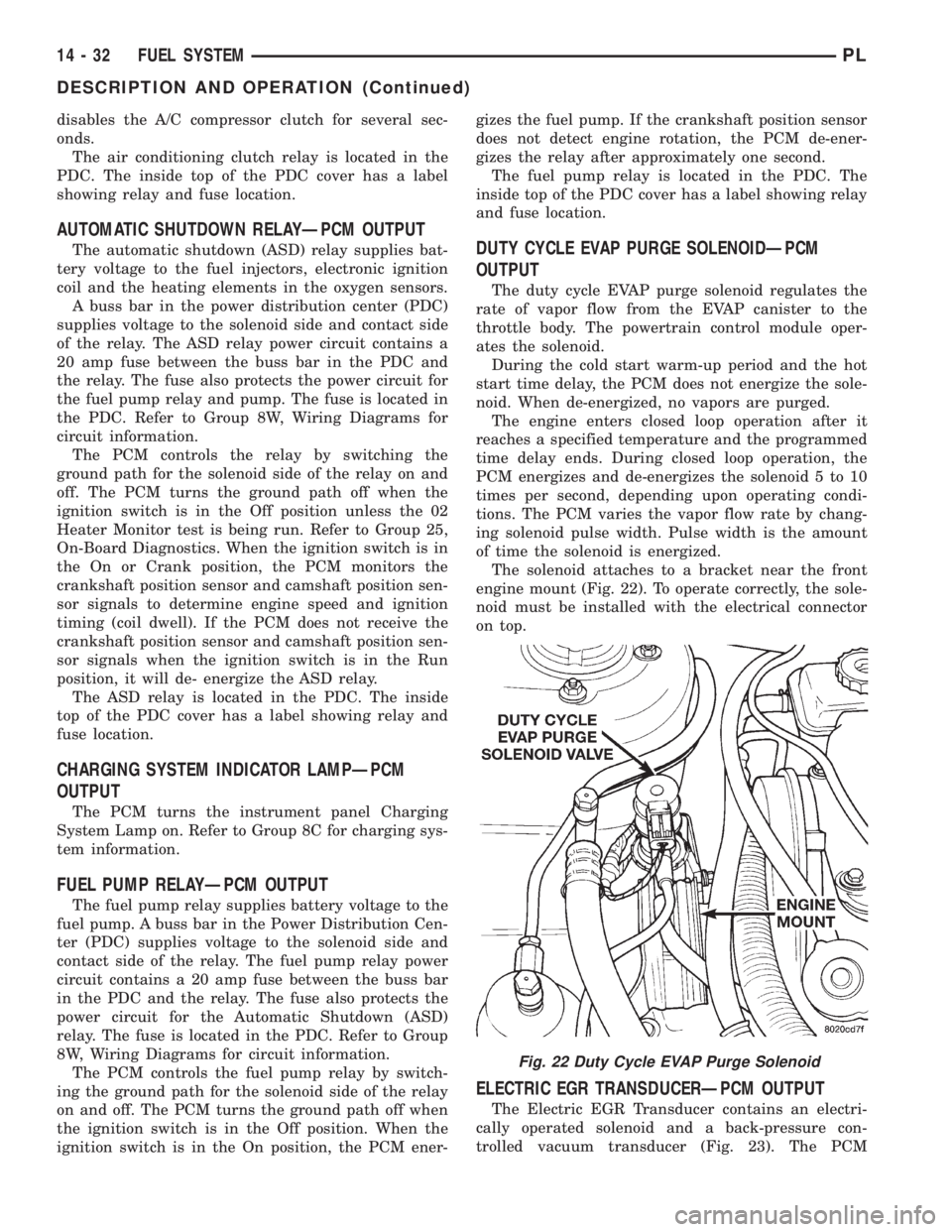
The solenoid attaches to a bracket near the front
engine mount (Fig. 22). To operate correctly, the sole-
noid must be installed with the electrical connector
on top.
ELECTRIC EGR TRANSDUCERÐPCM OUTPUT
The Electric EGR Transducer contains an electri-
cally operated solenoid and a back-pressure con-
trolled vacuum transducer (Fig. 23). The PCM
Fig. 22 Duty Cycle EVAP Purge Solenoid
14 - 32 FUEL SYSTEMPL
DESCRIPTION AND OPERATION (Continued)
Page 874 of 1200

operates the solenoid based on inputs from the multi-
port fuel injection system. The transducer and EGR
valve are serviced as an assembly.
When the PCM energizes the solenoid, vacuum
does not reach the transducer. Vacuum flows to the
transducer when the PCM de-energizes the solenoid.
When exhaust system back-pressure becomes high
enough, it fully closes a bleed valve in the vacuum
transducer. When the PCM de-energizes the solenoid
and back-pressure closes the transducer bleed valve,
vacuum flows through the transducer to operate the
EGR valve.
De-energizing the solenoid, but not fully closing the
transducer bleed hole (because of low back-pressure),
varies the strength of the vacuum signal applied to
the EGR valve. Varying the strength of the vacuum
signal changes the amount of EGR supplied to the
engine. This provides the correct amount of exhaust
gas recirculation for different operating conditions.
The transducer mounts to the clean air hose and
the EGR valve mount to the rear of the cylinder head
(Fig. 23).
GENERATOR FIELDÐPCM OUTPUT
The PCM regulates the charging system voltage
within a range of 12.9 to 15.0 volts. Refer to Group
8A for Battery system information and 8C for charg-
ing system information.
IDLE AIR CONTROL MOTORÐPCM OUTPUT
The Idle Air Control (IAC) motor is mounted on the
throttle body. The PCM operates the idle air control
motor (Fig. 24). The PCM adjusts engine idle speed
through the idle air control motor to compensate for
engine load, coolant temperature or barometric pres-
sure changes.
The throttle body has an air bypass passage that
provides air for the engine during closed throttle idle.The idle air control motor pintle protrudes into the
air bypass passage and regulates air flow through it.
The PCM adjusts engine idle speed by moving the
IAC motor pintle in and out of the bypass passage.
The adjustments are based on inputs the PCM
receives. The inputs are from the throttle position
sensor, crankshaft position sensor, coolant tempera-
ture sensor, MAP sensor, vehicle speed sensor and
various switch operations (brake, park/neutral, air
conditioning).
DATA LINK CONNECTOR
The data link connector (diagnostic connector)
links the DRB scan tool with the powertrain control
module (PCM). Refer to On-Board Diagnostics in the
General Diagnosis section of this group. The data
link connector is located inside the vehicle, under the
instrument panel, left of the steering column (Fig.
25).
Fig. 23 Electric EGR Backpressure TransducerÐ
Typical
Fig. 24 Idle Air Control Motor Air Bypass PassageÐ
Typical
Fig. 25 Data Link Connector
PLFUEL SYSTEM 14 - 33
DESCRIPTION AND OPERATION (Continued)
Page 876 of 1200

send incorrect signals. The PCM substitutes for the
incorrect signals with inputs from other sensors.
If the PCM detects active engine misfire severe
enough to cause catalyst damage, it flashes the MIL.
At the same time the PCM also sets a Diagnostic
Trouble Code (DTC).
For signals that can trigger the MIL (Check
Engine Lamp) refer to Group 25, On-Board
Dianostics.
SOLID STATE FAN RELAYÐPCM OUTPUT
The radiator fan runs when coolant temperature
and A/C system pressure demand cooling. The radia-
tor fan circuit contains a Solid State Fan Relay
(SSFR). Refer to the Group 8W for a circuit sche-
matic.
A 5 volt signal is supplied to the SSFR. The PCM
provides a pulsed ground for the SSFR. Depending
upon the amount of pulse on time, the SSFR puts out
a proportional voltage to the fan motor at the lower
speed. For instance, if the on time is 30 percent, then
the voltage to the fan motor will be 3.6 volts.
When engine coolant reaches approximately 99ÉC
(210ÉF) the PCM grounds the SSFR relay. When the
PCM grounds the relay it operates at a 30% duty
cycle and immediately ramps up to 100% duty cycle.
The PCM de-energizes the SSFR relay when coolant
temperature drops to approximately 93ÉC (199ÉF).
Also, when the air conditioning pressure switch
closes, the PCM grounds the SSFR. The air condi-
tioning switch closes at 285 psi610 psi. When air
conditioning pressure drops approximately 40 psi, the
pressure switch opens and the fan turns off.
The SSFR relay is located on the left front inner
frame just behind the radiator.
SPEED CONTROLÐPCM INPUT
The speed control system provides five separate
voltages (inputs) to the Powertrain Control Module
(PCM). The voltages correspond to the ON/OFF, SET,
RESUME and CANCEL.
The speed control ON voltage informs the PCM
that the speed control system has been activated.
The speed control SET voltage informs the PCM that
a fixed vehicle speed has been selected. The speed
control RESUME voltage indicates the previous fixed
speed is requested. The speed control CANCEL volt-
age tells the PCM to deactivate but retain set speed
in memory (same as depressing the brake pedal). The
speed control OFF voltage tells the PCM that the
speed control system has deactivated. Refer to Group
8H for more speed control information.
SCI RECEIVEÐPCM OUTPUT
SCI Receive is the serial data communication
receive circuit for the DRB scan tool. The Powertrain
Control Module (PCM) receives data from the DRB
through the SCI Receive circuit.
TACHOMETERÐPCM OUTPUT
The PCM operates the tachometer on the instru-
ment panel. The PCM calculates engine RPM from
the crankshaft position sensor input.
TORQUE CONVERTOR CLUTCH SOLENOIDÐPCM
OUTPUT
Three-speed automatic transaxles use a torque con-
verter clutch solenoid. The PCM controls the engage-
ment of the torque converter clutch through the
solenoid (Fig. 29). The torque converter clutch is
engaged up only in direct drive mode. Refer to Group
21 for transmission information.
DIAGNOSIS AND TESTING
VISUAL INSPECTIONÐSOHC
Before diagnosing or servicing the fuel injection
system, perform a visual inspection for loose, discon-
nected, or misrouted wires and hoses (Fig. 30). A
thorough visual inspection that includes the following
checks saves unnecessary test and diagnostic time.
(1) Inspect the battery connections. Clean corroded
terminals (Fig. 31).
(2) Check the 2 PCM 40-way connector for
stretched wires on pushed out terminals (Fig. 31).
Fig. 29 Torque Convertor Clutch Solenoid
PLFUEL SYSTEM 14 - 35
DESCRIPTION AND OPERATION (Continued)
Page 879 of 1200

(14) Check the electrical connection at the knock
sensor (Fig. 41).
(15) Check the electrical connections at the cam-
shaft position sensor and engine coolant temperature
sensor (Fig. 42).
(16) Check the electrical connector at the Elec-
tronic EGR Transducer. Inspect the vacuum and back
pressure hoses at the solenoid and transducer for
leaks (Fig. 43).
(17) Inspect the electrical connections at the gen-
erator (Fig. 44). Check the generator belt for glazing
or damage.
Fig. 39 Duty Cycle Purge Solenoid
Fig. 40 Starter Motor and Ground Strap
Fig. 41 Knock Sensor
Fig. 42 Camshaft Position Sensor and Engine
Coolant Temperature Sensor
Fig. 43 Electronic EGR Transducer
14 - 38 FUEL SYSTEMPL
DIAGNOSIS AND TESTING (Continued)
Page 880 of 1200

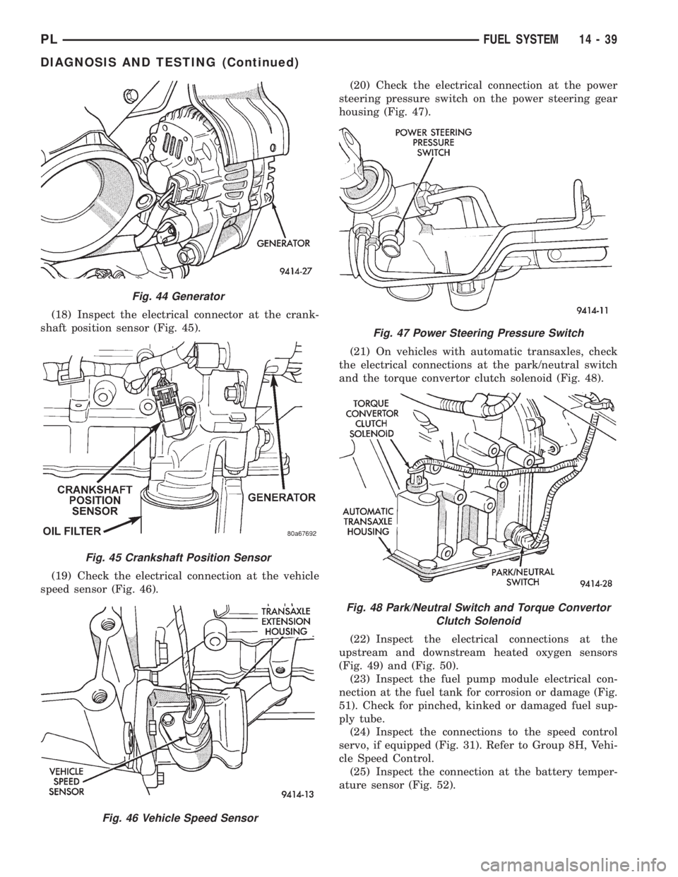
(18) Inspect the electrical connector at the crank-
shaft position sensor (Fig. 45).
(19) Check the electrical connection at the vehicle
speed sensor (Fig. 46).(20) Check the electrical connection at the power
steering pressure switch on the power steering gear
housing (Fig. 47).
(21) On vehicles with automatic transaxles, check
the electrical connections at the park/neutral switch
and the torque convertor clutch solenoid (Fig. 48).
(22) Inspect the electrical connections at the
upstream and downstream heated oxygen sensors
(Fig. 49) and (Fig. 50).
(23) Inspect the fuel pump module electrical con-
nection at the fuel tank for corrosion or damage (Fig.
51). Check for pinched, kinked or damaged fuel sup-
ply tube.
(24) Inspect the connections to the speed control
servo, if equipped (Fig. 31). Refer to Group 8H, Vehi-
cle Speed Control.
(25) Inspect the connection at the battery temper-
ature sensor (Fig. 52).
Fig. 44 Generator
Fig. 45 Crankshaft Position Sensor
Fig. 46 Vehicle Speed Sensor
Fig. 47 Power Steering Pressure Switch
Fig. 48 Park/Neutral Switch and Torque Convertor
Clutch Solenoid
PLFUEL SYSTEM 14 - 39
DIAGNOSIS AND TESTING (Continued)
Page 884 of 1200

(13) Inspect the air cleaner filter element. Replace
as necessary. Check the air induction system for
restrictions.
(14) Check the electrical connection at the knock
sensor (Fig. 64).
(15) Check the electrical connections at the cam-
shaft position sensor (Fig. 65) and engine coolant
temperature sensor (Fig. 66).
(16) Check the electrical connector at the Elec-
tronic EGR Transducer. Inspect the vacuum and back
pressure hoses at the solenoid and transducer for
leaks (Fig. 67).
(17) Inspect the electrical connections at the gen-
erator (Fig. 68). Check the generator belt for glazing
or damage.
Fig. 63 Starter Motor and Ground Strap
Fig. 64 Knock Sensor
Fig. 65 Camshaft Position Sensor
Fig. 66 Engine Coolant Temperature Sensor
Fig. 67 Electronic EGR Transducer
PLFUEL SYSTEM 14 - 43
DIAGNOSIS AND TESTING (Continued)
Page 885 of 1200

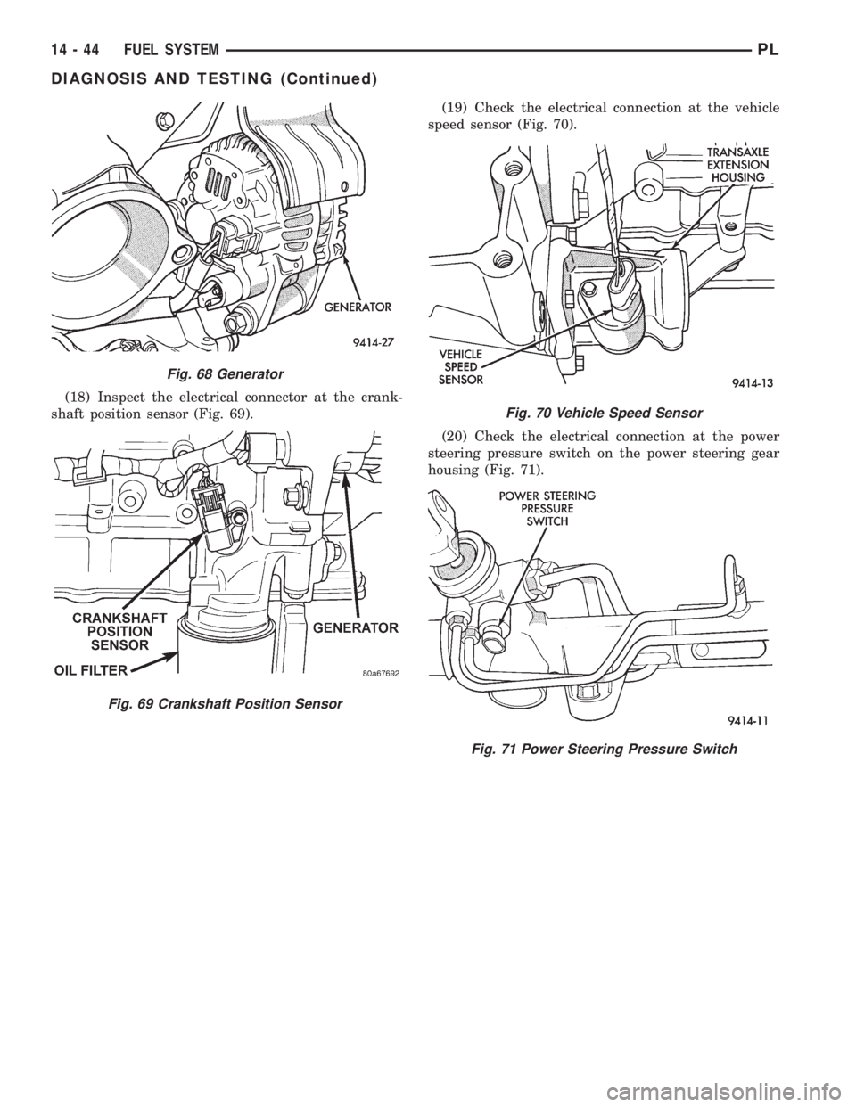
(18) Inspect the electrical connector at the crank-
shaft position sensor (Fig. 69).(19) Check the electrical connection at the vehicle
speed sensor (Fig. 70).
(20) Check the electrical connection at the power
steering pressure switch on the power steering gear
housing (Fig. 71).
Fig. 68 Generator
Fig. 69 Crankshaft Position Sensor
Fig. 70 Vehicle Speed Sensor
Fig. 71 Power Steering Pressure Switch
14 - 44 FUEL SYSTEMPL
DIAGNOSIS AND TESTING (Continued)
Page 888 of 1200

(7) Attach the other end of the jumper wire to
relay terminal 86. This activates the relay. The ohm-
meter should now show continuity between relay ter-
minals 87 and 30. The ohmmeter should not show
continuity between relay terminals 87A and 30.
(8) Disconnect jumper wires.
(9) Replace the relay if it did not pass the continu-
ity and resistance tests. If the relay passed the tests,
it operates properly. Check the remainder of the ASD
and fuel pump relay circuits. Refer to group 8W, Wir-
ing Diagrams.
CAMSHAFT AND CRANKSHAFT POSITION SENSOR
Refer to Group 8D, Ignition for Diagnosis and Test-
ing of Camshaft and Crankshaft Sensors.
ENGINE COOLANT TEMPERATURE SENSOR
(1) With the key off, disconnect wire harness con-
nector from coolant temperature sensor (Fig. 79) or
(Fig. 80).(2) Connect a high input impedance (digital) volt-
ohmmeter to terminals A and B (Fig. 81). The ohm-
meter should read as follows:
²Engine/Sensor at normal operating temperature
around 200ÉF should read approximately 700 to
1,000 ohms.
²Engine/Sensor at room temperature around 70ÉF
ohmmeter should read approximately 7,000 to 13,000
ohms.
(3) T
est the resistance of the wire harness between
the PCM 60-way connector terminal 28 and the sensor
harness connector. Also check for continuity between
PCM 60-way connector terminal 51 and the sensor har-
ness connector. Refer to Group 8W, Wiring diagrams for
circuit information. If the resistance is greater than 1
ohm, repair the wire harness as necessary.
HEATED OXYGEN SENSOR
Use an ohmmeter to test the heating element of
the oxygen sensors. Disconnect the electrical connec-
tor from each oxygen sensor. The white wires in the
sensor connector are the power and ground circuits
for the heater. Connect the ohmmeter test leads to
terminals of the white wires in the heated oxygen
sensor connector. Replace the heated oxygen sensor if
the resistance is not between 4 and 7 ohms.
IDLE AIR CONTROL (IAC) MOTOR TEST
To preform a complete test of IAC motor and its
circuitry, refer to DRB scan tool and the appropriate
Powertrain Diagnostics Procedures manual.
KNOCK SENSOR
The engine knock sensor is affected by a number of
factors. A few of these are: ignition timing, cylinder
pressure, fuel octane, etc. The knock sensor generates
an AC voltage whose amplitude increases with the
increase of engine knock. The knock sensor can be
tested with a digital voltmeter. The RMS voltage starts
Fig. 79 Engine Coolant Temperature Sensor
LocationÐSOHC
Fig. 80 Engine Coolant Temperature Sensor
LocationÐDOHC
Fig. 81 Engine Coolant Temperature Sensor
PLFUEL SYSTEM 14 - 47
DIAGNOSIS AND TESTING (Continued)