1999 DODGE NEON fuel pressure
[x] Cancel search: fuel pressurePage 721 of 1200

cause of low compression unless some malfunc-
tion is present.
(11) Clean or replace spark plugs as necessary
and adjust gap as specified in Group 8, Electrical.
Tighten to specifications.
(12) Test resistance of spark plug cables. Refer to
Group 8, Electrical Ignition System Secondary Cir-
cuit Inspection.
(13) Test coil output voltage, primary and second-
ary resistance. Replace parts as necessary. Refer to
Group 8, Electrical Ignition System.
(14) Check fuel pump pressure at idle and differ-
ent RPM ranges. Refer to Group 14, Fuel System for
Specifications.
(15) The air filter elements should be replaced as
specified in Group 0, Lubrication and Maintenance,.
(16) Inspect crankcase ventilation system as out
lined in Group 0, Lubrication and Maintenance. For
emission controls see Group 25, Emission Controls
for service procedures.
(17) Inspect and adjust accessory belt drives refer-
ring to Group 7, Cooling System, Accessory Drive
Belts for proper adjustments.
(18) Road test vehicle as a final test.
CYLINDER COMBUSTION PRESSURE LEAKAGE
TEST
The combustion pressure leakage test provides an
accurate means for determining engine condition.
Combustion pressure leakage testing will detect:
²Exhaust and intake valve leaks (improper seat-
ing).
²Leaks between adjacent cylinders or into water
jacket.
²Any causes for combustion/compression pressure
loss.
WARNING: DO NOT REMOVE THE RADIATOR CAP
WITH THE SYSTEM HOT AND UNDER PRESSURE
BECAUSE SERIOUS BURNS FROM COOLANT CAN
OCCUR.
Check the coolant level and fill as required. DO
NOT install the radiator cap.
Start and operate the engine until it attains nor-
mal operating temperature, then turn the engine
OFF.
Clean spark plug recesses with compressed air.
Remove the spark plugs.
Remove the oil filler cap.
Remove the air cleaner.
Calibrate the tester according to the manufactur-
er's instructions. The shop air source for testing
should maintain 483 kPa (70 psi) minimum, 1 379
kPa (200 psi) maximum and 552 kPa (80 psi) recom-
mended.Perform the test procedures on each cylinder
according to the tester manufacturer's instructions.
While testing, listen for pressurized air escaping
through the throttle body, tailpipe and oil filler cap
opening. Check for bubbles in the radiator coolant.
All gauge pressure indications should be equal,
with no more than 25% leakage.
FOR EXAMPLE:At 552 kPa (80 psi) input pres-
sure, a minimum of 414 kPa (60 psi) should be main-
tained in the cylinder.
LASH ADJUSTER (TAPPET) NOISE DIAGNOSIS
A tappet-like noise may be produced from several
items. Check the following items.
(1) Engine oil level too high or too low. This may
cause aerated oil to enter the adjusters and cause
them to be spongy.
(2) Insufficient running time after rebuilding cylin-
der head. Low speed running up to 1 hour may be
required.
(3) During this time, turn engine off and let set for
a few minutes before restarting. Repeat this several
times after engine has reached normal operating
temperature.
(4) Low oil pressure.
(5) The oil restrictor pressed into the vertical oil
passage to the cylinder head is plugged with debris.
(6) Air ingested into oil due to broken or cracked
oil pump pick up.
(7) Worn valve guides.
(8) Rocker arm ears contacting valve spring
retainer.
(9) Rocker arm loose, adjuster stuck or at maxi-
mum extension and still leaves lash in the system.
(10) Faulty lash adjuster.
a. Check lash adjusters for sponginess while
installed in cylinder head. Depress part of rocker
arm over adjuster. Normal adjusters should feel very
firm. Spongy adjusters can be bottomed out easily.
b. Remove suspected rocker arms (sohc) or lash
adjuster (dohc) and replace.
INSPECTION (ENGINE OIL LEAKS IN GENERAL)
Begin with a through visual inspection of the
engine, particularly at the area of the suspected leak.
If an oil leak source is not readily identifiable, the
following steps should be followed:
(1) Do not clean or degrease the engine at this
time because some solvents may cause rubber to
swell, temporarily stopping the leak.
(2) Add an oil soluble dye (use as recommended by
manufacturer). Start the engine and let idle for
approximately 15 minutes. Check the oil dipstick to
make sure the dye is thoroughly mixed as indicated
with a bright yellow color under a black light.
9 - 8 ENGINEPL
DIAGNOSIS AND TESTING (Continued)
Page 732 of 1200
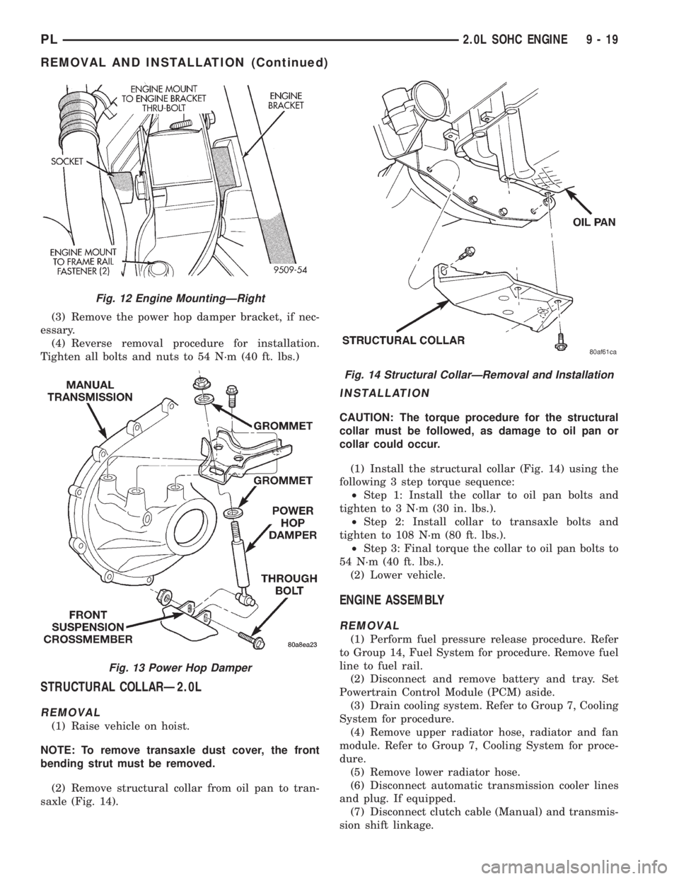
(3) Remove the power hop damper bracket, if nec-
essary.
(4) Reverse removal procedure for installation.
Tighten all bolts and nuts to 54 N´m (40 ft. lbs.)
STRUCTURAL COLLARÐ2.0L
REMOVAL
(1) Raise vehicle on hoist.
NOTE: To remove transaxle dust cover, the front
bending strut must be removed.
(2) Remove structural collar from oil pan to tran-
saxle (Fig. 14).
INSTALLATION
CAUTION: The torque procedure for the structural
collar must be followed, as damage to oil pan or
collar could occur.
(1) Install the structural collar (Fig. 14) using the
following 3 step torque sequence:
²Step 1: Install the collar to oil pan bolts and
tighten to 3 N´m (30 in. lbs.).
²Step 2: Install collar to transaxle bolts and
tighten to 108 N´m (80 ft. lbs.).
²Step 3: Final torque the collar to oil pan bolts to
54 N´m (40 ft. lbs.).
(2) Lower vehicle.
ENGINE ASSEMBLY
REMOVAL
(1) Perform fuel pressure release procedure. Refer
to Group 14, Fuel System for procedure. Remove fuel
line to fuel rail.
(2) Disconnect and remove battery and tray. Set
Powertrain Control Module (PCM) aside.
(3) Drain cooling system. Refer to Group 7, Cooling
System for procedure.
(4) Remove upper radiator hose, radiator and fan
module. Refer to Group 7, Cooling System for proce-
dure.
(5) Remove lower radiator hose.
(6) Disconnect automatic transmission cooler lines
and plug. If equipped.
(7) Disconnect clutch cable (Manual) and transmis-
sion shift linkage.
Fig. 12 Engine MountingÐRight
Fig. 13 Power Hop Damper
Fig. 14 Structural CollarÐRemoval and Installation
PL2.0L SOHC ENGINE 9 - 19
REMOVAL AND INSTALLATION (Continued)
Page 735 of 1200
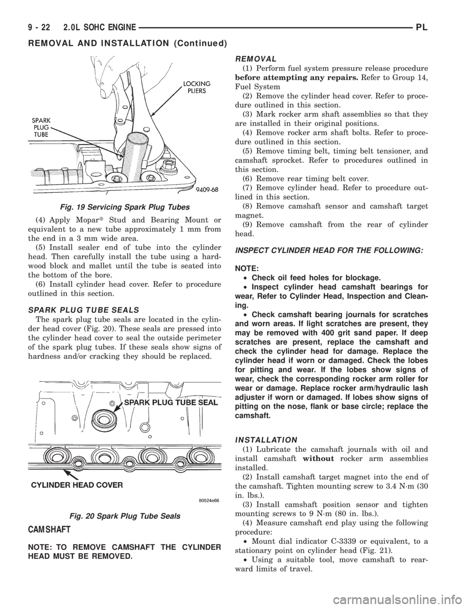
(4) Apply MopartStud and Bearing Mount or
equivalent to a new tube approximately 1 mm from
theendina3mmwide area.
(5) Install sealer end of tube into the cylinder
head. Then carefully install the tube using a hard-
wood block and mallet until the tube is seated into
the bottom of the bore.
(6) Install cylinder head cover. Refer to procedure
outlined in this section.
SPARK PLUG TUBE SEALS
The spark plug tube seals are located in the cylin-
der head cover (Fig. 20). These seals are pressed into
the cylinder head cover to seal the outside perimeter
of the spark plug tubes. If these seals show signs of
hardness and/or cracking they should be replaced.
CAMSHAFT
NOTE: TO REMOVE CAMSHAFT THE CYLINDER
HEAD MUST BE REMOVED.
REMOVAL
(1) Perform fuel system pressure release procedure
before attempting any repairs.Refer to Group 14,
Fuel System
(2) Remove the cylinder head cover. Refer to proce-
dure outlined in this section.
(3) Mark rocker arm shaft assemblies so that they
are installed in their original positions.
(4) Remove rocker arm shaft bolts. Refer to proce-
dure outlined in this section.
(5) Remove timing belt, timing belt tensioner, and
camshaft sprocket. Refer to procedures outlined in
this section.
(6) Remove rear timing belt cover.
(7) Remove cylinder head. Refer to procedure out-
lined in this section.
(8) Remove camshaft sensor and camshaft target
magnet.
(9) Remove camshaft from the rear of cylinder
head.
INSPECT CYLINDER HEAD FOR THE FOLLOWING:
NOTE:
²Check oil feed holes for blockage.
²Inspect cylinder head camshaft bearings for
wear, Refer to Cylinder Head, Inspection and Clean-
ing.
²Check camshaft bearing journals for scratches
and worn areas. If light scratches are present, they
may be removed with 400 grit sand paper. If deep
scratches are present, replace the camshaft and
check the cylinder head for damage. Replace the
cylinder head if worn or damaged. Check the lobes
for pitting and wear. If the lobes show signs of
wear, check the corresponding rocker arm roller for
wear or damage. Replace rocker arm/hydraulic lash
adjuster if worn or damaged. If lobes show signs of
pitting on the nose, flank or base circle; replace the
camshaft.
INSTALLATION
(1) Lubricate the camshaft journals with oil and
install camshaftwithoutrocker arm assemblies
installed.
(2) Install camshaft target magnet into the end of
the camshaft. Tighten mounting screw to 3.4 N´m (30
in. lbs.).
(3) Install camshaft position sensor and tighten
mounting screws to 9 N´m (80 in. lbs.).
(4) Measure camshaft end play using the following
procedure:
²Mount dial indicator C-3339 or equivalent, to a
stationary point on cylinder head (Fig. 21).
²Using a suitable tool, move camshaft to rear-
ward limits of travel.
Fig. 19 Servicing Spark Plug Tubes
Fig. 20 Spark Plug Tube Seals
9 - 22 2.0L SOHC ENGINEPL
REMOVAL AND INSTALLATION (Continued)
Page 738 of 1200
INSTALLATION
(1) Install valve seal/valve spring seat assembly
as outlined in the Valve Installation procedure in this
section.
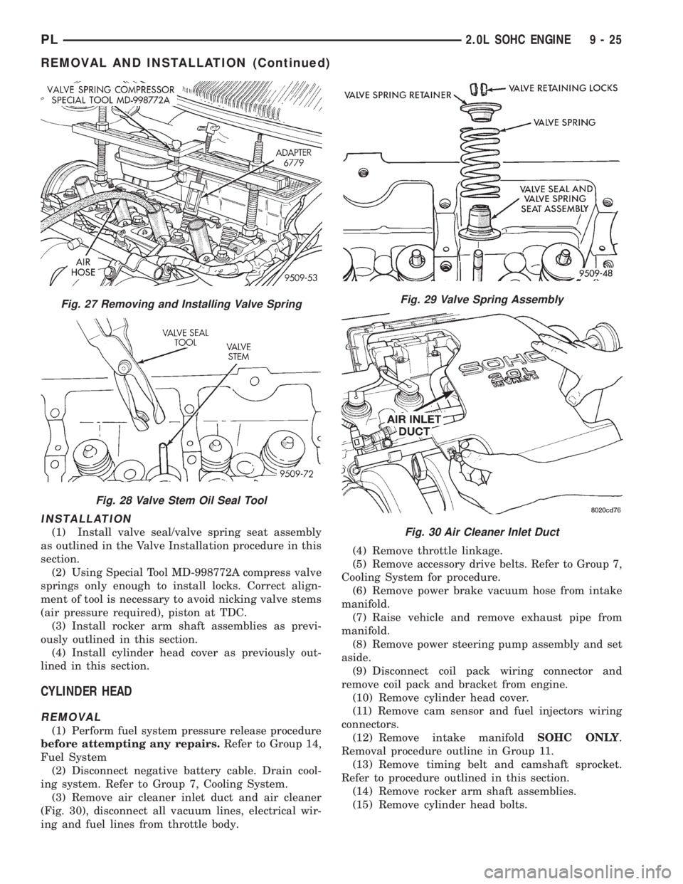
(2) Using Special Tool MD-998772A compress valve
springs only enough to install locks. Correct align-
ment of tool is necessary to avoid nicking valve stems
(air pressure required), piston at TDC.
(3) Install rocker arm shaft assemblies as previ-
ously outlined in this section.
(4) Install cylinder head cover as previously out-
lined in this section.
CYLINDER HEAD
REMOVAL
(1) Perform fuel system pressure release procedure
before attempting any repairs.Refer to Group 14,
Fuel System
(2) Disconnect negative battery cable. Drain cool-
ing system. Refer to Group 7, Cooling System.
(3) Remove air cleaner inlet duct and air cleaner
(Fig. 30), disconnect all vacuum lines, electrical wir-
ing and fuel lines from throttle body.(4) Remove throttle linkage.
(5) Remove accessory drive belts. Refer to Group 7,
Cooling System for procedure.
(6) Remove power brake vacuum hose from intake
manifold.
(7) Raise vehicle and remove exhaust pipe from
manifold.
(8) Remove power steering pump assembly and set
aside.
(9) Disconnect coil pack wiring connector and
remove coil pack and bracket from engine.
(10) Remove cylinder head cover.
(11) Remove cam sensor and fuel injectors wiring
connectors.
(12) Remove intake manifoldSOHC ONLY.
Removal procedure outline in Group 11.
(13) Remove timing belt and camshaft sprocket.
Refer to procedure outlined in this section.
(14) Remove rocker arm shaft assemblies.
(15) Remove cylinder head bolts.
Fig. 27 Removing and Installing Valve Spring
Fig. 28 Valve Stem Oil Seal Tool
Fig. 29 Valve Spring Assembly
Fig. 30 Air Cleaner Inlet Duct
PL2.0L SOHC ENGINE 9 - 25
REMOVAL AND INSTALLATION (Continued)
Page 778 of 1200
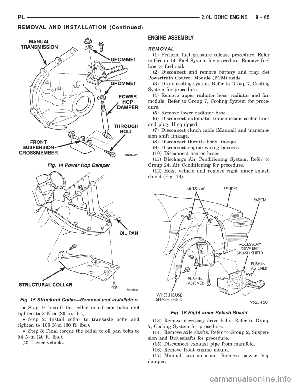
²Step 1: Install the collar to oil pan bolts and
tighten to 3 N´m (30 in. lbs.).
²Step 2: Install collar to transaxle bolts and
tighten to 108 N´m (80 ft. lbs.).
²Step 3: Final torque the collar to oil pan bolts to
54 N´m (40 ft. lbs.).
(2) Lower vehicle.
ENGINE ASSEMBLY
REMOVAL
(1) Perform fuel pressure release procedure. Refer
to Group 14, Fuel System for procedure. Remove fuel
line to fuel rail.
(2) Disconnect and remove battery and tray. Set
Powertrain Control Module (PCM) aside.
(3) Drain cooling system. Refer to Group 7, Cooling
System for procedure.
(4) Remove upper radiator hose, radiator and fan
module. Refer to Group 7, Cooling System for proce-
dure.
(5) Remove lower radiator hose.
(6) Disconnect automatic transmission cooler lines
and plug. If equipped.
(7) Disconnect clutch cable (Manual) and transmis-
sion shift linkage.
(8) Disconnect throttle body linkage.
(9) Disconnect engine wiring harness.
(10) Disconnect heater hoses.
(11) Discharge Air Conditioning System. Refer to
Group 24, Air Conditioning for procedure.
(12) Hoist vehicle and remove right inner splash
shield (Fig. 16).
(13) Remove accessory drive belts. Refer to Group
7, Cooling System for procedure.
(14) Remove axle shafts. Refer to Group 2, Suspen-
sion and Driveshafts for procedure.
(15) Disconnect exhaust pipe from manifold.
(16) Remove front engine mount.
(17) Manual transmission: Remove power hop
damper.
Fig. 14 Power Hop Damper
Fig. 15 Structural CollarÐRemoval and Installation
Fig. 16 Right Inner Splash Shield
PL2.0L DOHC ENGINE 9 - 65
REMOVAL AND INSTALLATION (Continued)
Page 785 of 1200
REMOVAL
(1) Perform fuel system pressure release procedure
before attempting any repairs.Refer to Group 14,
Fuel System.
(2) Disconnect negative battery cable. Drain cool-
ing system. Refer to Group 7, Cooling System.
(3) Remove air cleaner duct and air cleaner, dis-
connect all vacuum lines, electrical wiring and fuel
line from fuel rail and throttle body.
(4) Remove throttle linkage.
(5) Remove accessory drive belts. Refer to Group 7,
Cooling System for procedure.
(6) Remove power brake vacuum hose from intake
manifold.
(7) Raise vehicle and remove exhaust pipe from
manifold.
(8) Remove power steering pump assembly and set
aside.
(9) Disconnect coil pack wiring connector and
remove coil pack from engine.
(10) Remove cam sensor and fuel injectors wiring
connectors.
(11) Remove timing belt, timing belt tensioner, and
camshaft sprocket. Refer to procedure outlined in
this section.
(12) Remove inner timing belt cover.
(13) Remove cylinder head cover.
(14) Remove camshaft and cam follower assem-
blies. Refer to Camshaft Service for removal proce-
dure outlined in this section.
(15) Remove cylinder head bolts.
CAUTION: Use only a plastic scraper to remove
gasket material on the aluminum head sealing sur-
faces to prevent damage to cylinder head.
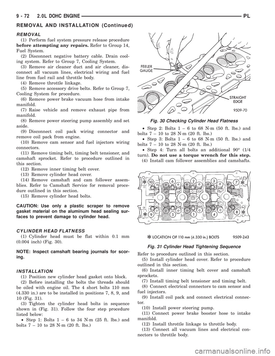
CYLINDER HEAD FLATNESS
(1) Cylinder head must be flat within 0.1 mm
(0.004 inch) (Fig. 30).
NOTE: Inspect camshaft bearing journals for scor-
ing.
INSTALLATION
(1) Position new cylinder head gasket onto block.
(2) Before installing the bolts the threads should
be oiled with engine oil. The 4 short bolts 110 mm
(4.330 in.) are to be installed in positions 7, 8, 9, and
10 (Fig. 31).
(3) Tighten the cylinder head bolts in sequence
shown in (Fig. 31). Follow the four step procedure
listed below:
²Step 1: Bolts1±6to34N´m(25ft.lbs.) and
bolts7±10to28N´m(20ft.lbs.)²Step 2: Bolts1±6to68N´m(50ft.lbs.) and
bolts7±10to28N´m(20ft.lbs.)
²Step 3: Bolts1±6to68N´m(50ft.lbs.) and
bolts7±10to28N´m(20ft.lbs.)
²Step 4: Turn all bolts an additional 90É (1/4
turn).Do not use a torque wrench for this step.
(4) Install cam follower assemblies and camshafts.
Refer to procedure outlined in this section.
(5) Install cylinder head cover. Refer to procedure
outlined in this section.
(6) Install inner timing belt cover and camshaft
sprockets.
(7) Install timing belt tensioner and timing belt.
(8) Connect electrical connectors to cam sensor and
fuel injectors.
(9) Install coil pack and connect electrical connec-
tor.
(10) Install power steering pump.
(11) Connect power brake booster hose to intake
manifold.
(12) Install throttle linkage to throttle body.
(13) Connect all vacuum lines and electrical con-
nectors to throttle body.
Fig. 30 Checking Cylinder Head Flatness
Fig. 31 Cylinder Head Tightening Sequence
9 - 72 2.0L DOHC ENGINEPL
REMOVAL AND INSTALLATION (Continued)
Page 819 of 1200
DIAGNOSIS AND TESTING
REMOVAL AND INSTALLATION
EXHAUST PIPE AND MUFFLER
REMOVAL
(1) Raise vehicle on hoist and apply penetrating oil
to band clamp fastener of component being removed
(Fig. 6).NOTE: Do not use petroleum-based lubricants
when removing/installing muffler or exhaust pipe
isolators as it may compromise the life of the part.
A suitable substitute is a mixture of liquid dish
soap and water.
(2) Loosen band clamp and remove support insula-
tors at muffler (Fig. 7). Remove muffler from exhaust
pipe.
EXHAUST SYSTEM DIAGNOSIS CHART
CONDITION POSSIBLE CAUSES CORRECTION
EXCESSIVE EXHAUST NOISE
(UNDER HOOD)1. Exhaust manifold cracked or
broken.1. Replace manifold.
2. Manifold to cylinder head leak. 2. Tighten manifold and/or replace
gasket.
3. EGR Valve Leakage. 3. See Below:
(a) EGR valve to manifold gasket. (a) Tighten bolts and/or replace
gasket.
(b) EGR valve to EGR tube gasket. (b) Tighten bolts and/or replace
gasket.
(c) EGR tube to intake manifold
gasket.(c) Tighten bolts and/or replace
gasket.
4. Exhaust flex joint. (non LEV) 4. See Below:
(a) Spring height, not correctly
installed.(a) Check spring height, both sides
(specification is 32.5 mm, 1.28 inch)
look for source of spring height
variation if out of specification
(b) Exhaust sealing ring defective. (b) Inspect seal for damage on
round spherical surface. If no
damage is evident, check for
exhaust restriction causing high back
pressure on heavy acceleration.
5. Exhaust Flex joint to manifold
leak (LEV).5.Tighten nuts or replace gasket.
6. Exhaust flex joint (LEV). 6. Replace catalytic converter
assembly.
7. Pipe and shell noise from front
exhaust pipe.7. Characteristic of single wall pipes.
EXCESSIVE EXHAUST NOISE 1. Leaks at pipe joints. 1. Tighten or replace clamps at
leaking joints.
2. Burned, blown, or rusted out
exhaust pipe or muffler.2. Replace muffler or exhaust pipes.
3. Restriction in muffler or tailpipe. 3. Remove restriction, if possible or
replace as necessary.
4. Catalytic converter material in
muffler.4. replace muffler and converter
assembly. Check fuel injection and
ignition systems for proper operation.
11 - 4 EXHAUST SYSTEM AND INTAKE MANIFOLDPL
Page 821 of 1200
NOTE: When replacement is required on any com-
ponent of the exhaust system, you must use origi-
nal equipment parts (or their equivalent).
INSTALLATION
When assembling exhaust systemdo nottighten
clamps until components are aligned and clearances
are checked.
(1) Assemble catalytic convertor to exhaust mani-
fold connection. Use a new flange gasket (LEV only)
(Fig. 9) or (Fig. 10).
(2) Assemble exhaust pipe to catalytic convertor
and the support to the underbody
(3) Install the muffler to exhaust pipe and the sup-
ports to the underbody.
(4) Working from the front of system;
(5) Align and tighten the catalytic convertor to
exhaust manifold ball joint bolts to 27 N´m (20 ft.
lbs.) (Fig. 9) or flex-joint attaching nuts (LEV) to 28
N´m (250 in. lbs.).
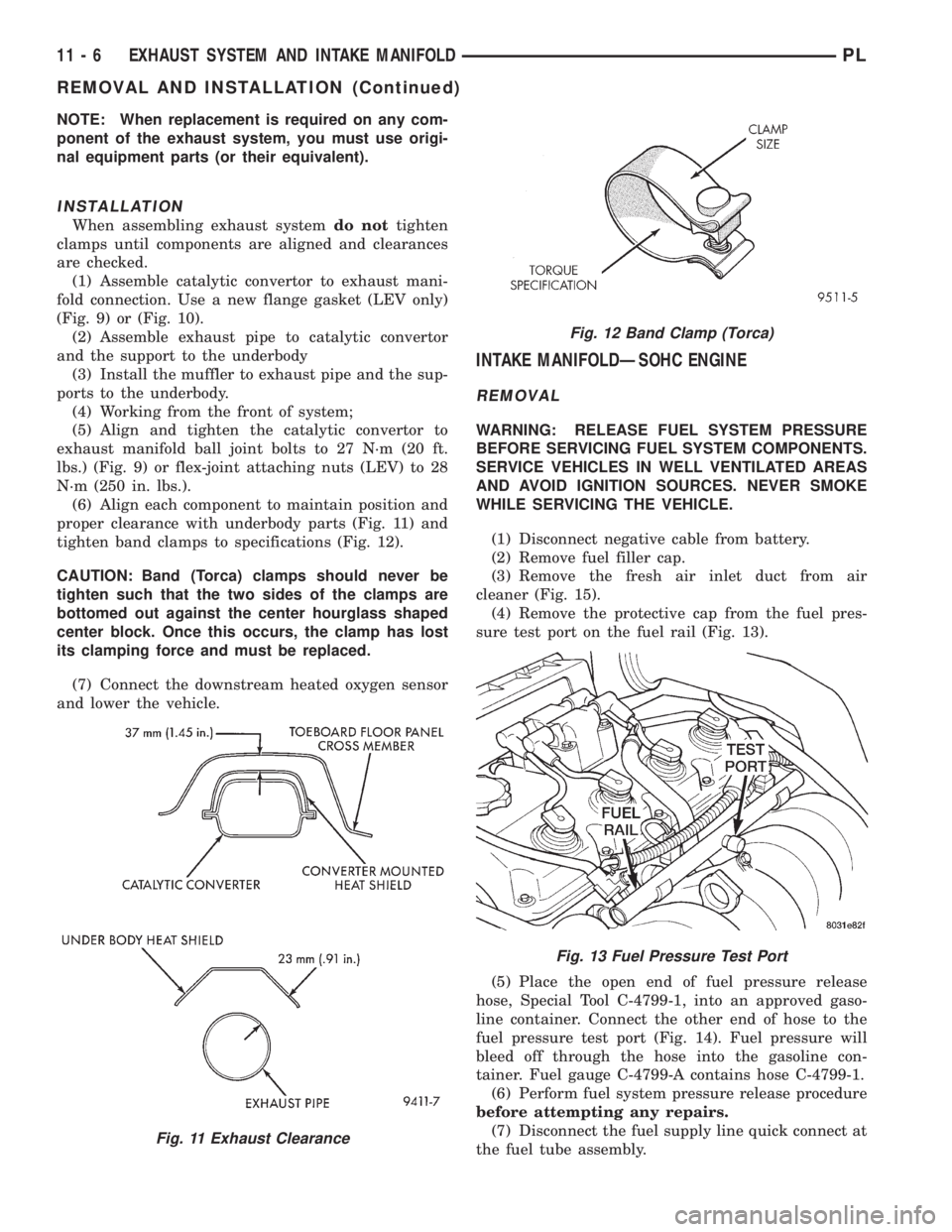
(6) Align each component to maintain position and
proper clearance with underbody parts (Fig. 11) and
tighten band clamps to specifications (Fig. 12).
CAUTION: Band (Torca) clamps should never be
tighten such that the two sides of the clamps are
bottomed out against the center hourglass shaped
center block. Once this occurs, the clamp has lost
its clamping force and must be replaced.
(7) Connect the downstream heated oxygen sensor
and lower the vehicle.
INTAKE MANIFOLDÐSOHC ENGINE
REMOVAL
WARNING: RELEASE FUEL SYSTEM PRESSURE
BEFORE SERVICING FUEL SYSTEM COMPONENTS.
SERVICE VEHICLES IN WELL VENTILATED AREAS
AND AVOID IGNITION SOURCES. NEVER SMOKE
WHILE SERVICING THE VEHICLE.
(1) Disconnect negative cable from battery.
(2) Remove fuel filler cap.
(3) Remove the fresh air inlet duct from air
cleaner (Fig. 15).
(4) Remove the protective cap from the fuel pres-
sure test port on the fuel rail (Fig. 13).
(5) Place the open end of fuel pressure release
hose, Special Tool C-4799-1, into an approved gaso-
line container. Connect the other end of hose to the
fuel pressure test port (Fig. 14). Fuel pressure will
bleed off through the hose into the gasoline con-
tainer. Fuel gauge C-4799-A contains hose C-4799-1.
(6) Perform fuel system pressure release procedure
before attempting any repairs.
(7) Disconnect the fuel supply line quick connect at
the fuel tube assembly.
Fig. 11 Exhaust Clearance
Fig. 12 Band Clamp (Torca)
Fig. 13 Fuel Pressure Test Port
11 - 6 EXHAUST SYSTEM AND INTAKE MANIFOLDPL
REMOVAL AND INSTALLATION (Continued)