1999 DODGE NEON fuel pressure
[x] Cancel search: fuel pressurePage 633 of 1200

CAV CIRCUIT FUNCTION
1 M2 20YL* DOOR LIFT GROUND SWITCH
2 G34 16RD/GY HIGH BEAM INDICATOR DRIVER
2 L3 16RD/OR** DIMMER SWITCH HIGH BEAM OUTPUT
3 L60 22TN RIGHT TURN SIGNAL
4 G10 20LG/RD SEAT BELT SWITCH SENSE
5 G5 20DB/WT FUSED IGNITION SWITCH OUTPUT (ST-RUN)
6 M1 22PK FUSED B(+)
7 G21 22GY/LB TACHOMETER SIGNAL
8 Z3 16BK/OR GROUND
9 R41 18BK/TN AIRBAG WARNING LAMP DRIVER
10 G7 22WT/OR VEHICLE SPEED SENSOR SIGNAL
BLACK
51
10 6
** RKE
CAV CIRCUIT FUNCTION
1 G6 22GY OIL PRESSURE SWITCH SENSE
2 G19 22LG/OR ABS WARNING LAMP DRIVER
3 G3 22BK/PK CHECK ENGINE LAMP DRIVER
4 G20 22VT/YL ECT GAUGE SENSOR SIGNAL
5 G26 20LB KEY-IN IGNITION SWITCH SENSE
6 G9 22GY/BK RED BRAKE WARNING LAMP DRIVER
7 G12 22TN/BK GENERATOR LAMP DRIVER
8 L61 22LG LEFT TURN SIGNAL
9 E2 22OR PANEL LAMPS DRIVER
10 G4 20DB FUEL LEVEL SENSOR SIGNAL
BLACK
51
10 6
INSTRUMENT
CLUSTER - C1
CLUSTER - C2INSTRUMENT
* LHD
8W - 80 - 24 8W-80 CONNECTOR PIN-OUTSPL
J988W-1PL008024
Page 642 of 1200

CAV CIRCUIT FUNCTION
1 Q42 18LB POWER SUNROOF CLOSE
2- -
3 Q41 18WT POWER SUNROOF OPEN
4 Q46 18OR POWER SUNROOF VENT OPEN/CLOSE LIMIT
5 Q43 18VT POWER SUNROOF VENT
6 Z8 18BK/VT GROUND
RED
3 2 14 5 6
CAV CIRCUIT FUNCTION
41 V37 20RD/LG* SPEED CONTROL SWITCH SIGNAL
42 - -
43 K4 20BK/LB SENSOR GROUND
44 K7 20OR 8 VOLT SUPPLY
45 K10 20WT POWER STEERING PRESSURE SWITCH SENSE
46 A14 18RD/WT FUSED B(+)
47 Z11 20BK/WT GROUND
48 K40 20BR/WT IDLE AIR CONTROL MOTOR NO. 3 DRIVER
49 K60 20YL/BK IDLE AIR CONTROL MOTOR NO. 2 DRIVER
50 Z12 20BK/TN GROUND
51 K141 20TN/WT DOWNSTREAM HEATED OXYGEN SENSOR SIGNAL
52 G31 18VT/LG AMBIENT TEMPERATURE SENSOR SIGNAL
53 - -
54 - -
55 - -
56 G12 20TN/BK GENERATOR LAMP DRIVER
57 K39 20GY/RD IDLE AIR CONTROL MOTOR NO. 1 DRIVER
58 K59 20VT IDLE AIR CONTROL MOTOR NO. 4 DRIVER
59 - -
60 - -
50 41
60 51
70 61
80 71BLACK
-
CONTROL SOLENOID VENT CONTROL SPEED 20LG/RD* V35 80CONTROL SOLENOID CLUTCH CONVERTOR TORQUE 20OR/BK** K54 79
- - 79
CONTROL SOLENOID VACUUM CONTROL SPEED 20TN/RD* V36 78
DRIVER SOLENOID CANISTER VAPOR 18WT/LG K106 77
SENSE SWITCH POSITION PARK/NEUTRAL 20BR/YL** T41 76
- - 76
RECEIVE SCI 20LG D20 75
CONTROL RELAY PUMP FUEL 18BR K31 74
SIGNAL TACHOMETER 20GY/LB G21 73
DRIVER SWITCH PUMP CANISTER VAPOR 18OR K107 72
- 71
- - 70
- - 69
CONTROL SOLENOID EVAP/PURGE CYCLE DUTY 20PK/BK K52 68
CONTROL RELAY DOWN SHUT AUTOMATIC 18DB/YL K51 67
SIGNAL SENSOR SPEED VEHICLE 20WT/OR G7 66
TRANSMIT SCI 20PK D21 65
CONTROL RELAY CLUTCH COMPRESSOR A/C 18DB/OR C28 64
- - 63
SENSE SWITCH LAMP STOP 20WT/PK K29 62
SUPPLY VOLT 5 20VT/WT K6 61
MODULE - C1CONTROL POWERTRAINMOTOR SUNROOFPOWER
* SPEED CONTROL
** ATX
EXCEPT BUILT-UP-EXPORT
2.0L
PL8W-80 CONNECTOR PIN-OUTS 8W - 80 - 33
PL008033J988W-1
Page 643 of 1200

CAV CIRCUIT FUNCTION
1- -
2 K19 18BK/GY IGNITION COIL NO. 1, 3 DRIVER
3 K17 18DB/TN IGNITION COIL NO. 2, 4 DRIVER
4 K20 18DG GENERATOR FIELD DRIVER
5 V32 20YL/RD SPEED CONTROL FEED
6 A142 18DG/OR AUTOMATIC SHUT DOWN RELAY OUTPUT
7 K13 18YL/WT FUEL INJECTOR NO. 3 DRIVER
8 G3 20BK/PK CHECK ENGINE LAMP DRIVER
9- -
10 Z12 18BK/TN GROUND
11 - -
12 - -
13 K11 18WT/DB FUEL INJECTOR NO. 1 DRIVER
14 - -
15 - -
16 K14 18LB/BR
17 K12 18TN
18 K173 20LG
19 - -
20F12 18DB/WT FUSED IGNITION SWITCH OUTPUT (ST-RUN)
21 - -
22 - -
23 G4 20DB FUEL LEVEL SENSOR SIGNAL
24 K42 20BK/LG** KNOCK SENSOR SIGNAL
24 K42 20DB/LG** KNOCK SENSOR SIGNAL
31 40
21 30
11 20
110
BLACK
CONTROL SOLENOID RECIRCULATION GAS EXHAUST 20GY/YL K35 40- - 39
SENSE SWITCH A/C 18BR/OR C20 38
SIGNAL SENSOR POSITION THROTTLE 20OR/DB K22 35
- - 34
SIGNAL SENSOR POSITION CAMSHAFT 20TN/YL K44 33
SIGNAL SENSOR POSITION CRANKSHAFT 20GY/BK K24 32
- - 31
SIGNAL SENSOR OXYGEN HEATED UPSTREAM 20BK/DG K41 30
- - 29
- - 28
- - 27
SIGNAL SENSOR TEMPERATURE COOLANT ENGINE 20TN/BK** K2 26
SIGNAL SENSOR TEMPERATURE COOLANT ENGINE 20TN/DB* K2 26
- - 25
POWERTRAIN
CONTROL
MODULE - C2
20DB/WT F12 (ST-RUN)OUTPUT SWITCH IGNITION FUSED
24K42 20DB/LG KNOCK SENSOR SIGNAL
* 1.8L/2.0L SOHC
** 2.0L DOHC
1.8L
2.0L 36 K1 20DG/RD MANIFOLD ABSOLUTE PRESSURE SENSOR SIGNAL
37 K21 20BK/RD INTAKE AIR TEMPERATURE SENSOR SIGNAL
FUEL INJECTOR NO. 4 DRIVER
FUEL INJECTOR NO. 2 DRIVER
SOLID STATE RELAY CONTROL
8W - 80 - 34 8W-80 CONNECTOR PIN-OUTSPL
J988W-1PL008034
Page 677 of 1200

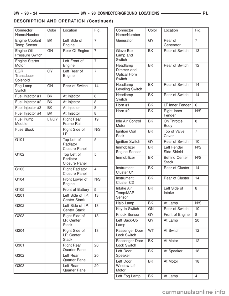
Connector
Name/NumberColor Location Fig.
Engine Coolant
Temp SensorBK Left Side of
Engine7
Engine Oil
Pressure SwitchGN Rear Of Engine 7
Engine Starter
MotorLeft Front of
Engine7
EGR
Transducer
SolenoidGY Left Rear of
Engine7
Fog Lamp
SwitchGN Rear of Switch 14
Fuel Injector #1 BK At Injector 8
Fuel Injector #2 BK At Injector 8
Fuel Injector #3 BK At injector 8
Fuel Injector #4 BK At Injector 8
Fuel Pump
ModuleLT/GY Right Rear
Frame Rail19
Fuse Block Right Side of
I.P.N/S
G101 Top Left of
Radiator
Closure Panel5
G102 Top Left of
Radiator
Closure Panel5
G103 Right Radiator
Closure Panel4
G104 Front Lower of
EngineN/S
G105 Front of Battery 5
G201 Left Side of I.P.
Center Stack13
G202 Left Side of I.P.
Center Stack13
G203 Right Side of
I.P. Center
Stack13
G204 Right Side of
I.P. Center
Stack13
G301 Right Rear
Quarter Panel20
G302 Left Rear
Quarter Panel20
G303 Left Rear
Quarter Panel20Connector
Name/NumberColor Location Fig.
Generator GY Rear of
Generator7
Glove Box
Lamp and
SwitchBK Rear of Switch 13
Headlamp
Dimmer and
Optical Horn
SwitchBK Rear of Switch 12
Headlamp
Leveling SwitchBK Rear of Switch 14
Headlamp
SwitchBK Rear of Switch 14
Horn #1 BK LT Inner Fender 6
Horn #2 BK Right Inner
FenderN/S
Idle Air Control
MotorBK On Throttle
Body8
Ignition Coil
PackBK Top of Valve
Cover7
Ignition Switch GY Rear of Switch 10
Immobilizer
Engine SensorBK Left Fender
Side ShieldN/S
Immobilizer BK Behind Center
StackN/S
Instrument
Cluster C1BK Rear of Cluster 14
Instrument
Cluster C2BK Rear of Cluster 14
Intake Air
Temp/MAP
SensorBK Left Side of
Intake8
Halo Lamp BK At Lamp N/S
Key-In Switch GN Rear of Switch 10
Knock Sensor GY Front of Engine 8
Left Back-Up
LampGY At Lamp 20
Passenger Door
Lock SwitchWT At Switch 12
Passenger Door
Lock SwitchBK At Motor 12
Left Door
SpeakerBK At Speaker 18
Left Door
Window Lift
MotorBK At Motor 18
Left Fog Lamp BK At Lamp 4
8W - 90 - 24 8W - 90 CONNECTOR/GROUND LOCATIONSPL
DESCRIPTION AND OPERATION (Continued)
Page 704 of 1200

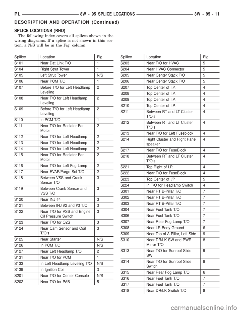
SPLICE LOCATIONS (RHD)
The following index covers all splices shown in the
wiring diagrams. If a splice is not shown in this sec-
tion, a N/S will be in the Fig. column.
Spllice Location Fig.
S101 Near Dat Link T/O 1
S104 Right Strut Tower 1
S105 Left Strut Tower N/S
S106 Near PCM T/O 1
S107 Before T/O for Left Headlamp
Leveling2
S108 Near T/O for Left Headlamp
Leveling2
S109 Before T/O for Left Headlamp
Leveling2
S110 In PCM T/O 1
S111 Near T/O for Radiator Fan
Motor2
S112 Near T/O for Left Headlamp 2
S113 Near T/O for Left Headlamp 2
S114 Near T/O for Left Headlamp 2
S115 Near T/O for Radiator Fan
Motor2
S116 Near T/O for Left Fog Lamp 2
S117 Near EVAP/Purge Sol T/O 2
S118 Between VSS and Crank
Sensor T/O3
S119 Between Crank Sensor and
VSS T/O3
S120 Near INJ #4 3
S121 Between INJ #2 and #3 T/O 3
S122 Near T/O for VSS and Engine
Oil Pressure Switch3
S123 Near T/O for O2S 3
S124 Near Cam Sensor and Coil
T/O's3
S125 Near Starter N/S
S126 In PCM T/O N/S
S127 Near Left Headlamp T/O 2
S131 Near T/O for PCM 1
S133 In Left Headlamp Leveling T/O N/S
S139 In Ignition Coil 3
S201 Near T/O for Center Console N/S
S202 Near T/O for PAB 5
Spllice Location Fig.
S203 Near T/O for HVAC 5
S204 Near HVAC Connector 5
S205 Near Center Stack T/O 5
S206 Near Center Stack T/O 5
S207 Top Center of I.P. 4
S208 Top Center of I.P. 4
S209 Top Center of I.P. 4
S210 Top Center of I.P. 4
S211 Between RT and LT Cluster
T/O's4
S212 Between RT and LT Cluster
T/O's4
S213 Near T/O for Left Fuseblock 4
S214 Right Cluster and Right Panel
speaker4
S217 Near T/O for FuseBlock 4
S218 Between RT and LT Cluster
T/O's4
S221 Top Right of I.P. 4
S222 Near T/O for FuseBlock 4
S223 Top Center of I/P 5
S224 In T/O for Headlamp Switch 4
S301 Near RT B-Pillar T/O 7
S302 Near RT B-Pillar T/O 7
S303 Near RT B-Pillar T/O 7
S304 Near Fuel Tank T/O 7
S306 Near Fuel Tank T/O 7
S307 Near Rear Fog Lamp T/O 7
S308 Near LR Body Ground 6
S309 Near Top of A-Pillar, Left Side 9
S310 Near DR/LK SW and PWR
Mirror T/O8
S313 Near T/O for Sunroof Slide
SW9
S314 Near T/O for Sunroof Slide
Switch9
S315 Near Rear Fog Lamp T/O 6
S316 Near Fuel Tank T/O 7
S317 Near Fuel Tank T/O 7
S318 Near DR/LK Switch T/O 8
PL8W - 95 SPLICE LOCATIONS 8W - 95 - 11
DESCRIPTION AND OPERATION (Continued)
Page 715 of 1200

assure gasket rails are flat. Flatten rails with a ham-
mer on a heavy steel plate if required. Gasket sur-
faces must be free of oil and dirt. Make sure old
gasket material is removed from blind attaching
holes.
FORM-IN-PLACE GASKET APPLICATION
Assembling parts using a form-in-place gasket
requires care but it's easier then using precut gas-
kets.
MopartGasket Maker material should be applied
sparingly 1 mm (0.040 inch.) diameter or less of seal-
ant to one gasket surface. Be certain the material
surrounds each mounting hole. Excess material can
easily be wiped off. Components should be torqued in
place within 15 minutes. The use of a locating dowel
is recommended during assembly to prevent smear-
ing material off the location.
The MopartSilicone Rubber Adhesive Sealant gas-
ket material or equivalent should be applied in a con-
tinuous bead approximately 3 mm (0.120 inch) in
diameter. All mounting holes must be circled. For
corner sealing, a 3.17 or 6.35 mm (1/8 or 1/4 inch.)
drop is placed in the center of the gasket contact
area. Uncured sealant may be removed with a shop
towel. Components should be torqued in place while
the sealant is still wet to the touch (within 10 min-
utes). The usage of a locating dowel is recommended
during assembly to prevent smearing material off the
location.
CRANKSHAFT SPROCKET BOLT ACCESS PLUG
An Access plug is located in the right inner fender
shield. Remove the plug and insert the proper size
socket, extension and ratchet, when crankshaft rota-
tion is necessary.
ENGINE CORE PLUGS
REMOVAL
Using a blunt tool such as a drift or a screwdriver
and a hammer, strike the bottom edge of the cup
plug (Fig. 1). With the cup plug rotated, grasp firmly
with pliers or other suitable tool and remove plug
(Fig. 1).
CAUTION: Do not drive cup plug into the casting
as restricted cooling can result and cause serious
engine problems.
INSTALLATION
Thoroughly remove all rust and clean inside of cup
plug hole in cylinder block or head. Be sure to
remove old sealer. Lightly coat inside of cup plug hole
with sealer. Make certain the new plug is cleaned of
all oil or grease. Using proper drive plug, drive plug
into hole so that the sharp edge of the plug is atleast 0.5 mm (0.020 inch.) inside the lead in chamfer
(Fig. 1).
It is in not necessary to wait for curing of the seal-
ant. The cooling system can be refilled and the vehi-
cle placed in service immediately.
ENGINE PERFORMANCE
If a loss of performance is noticed, timing belt or
chain may have skipped one or two teeth. Camshaft
and crankshaft timing should be checked. Refer to
Group 9, Engine Timing belt or chain installation.
It is important that the vehicle is operating to its
optimum performance level to maintain fuel economy
and lowest vehicle emissions. If vehicle is not operat-
ing to these standards, refer to Engine Diagnosis out-
lined is this section. The following procedures can
assist in achieving the proper engine diagnosis.
(1) Test cranking amperage draw. Refer to Group
8B, Starting.
(2) Check intake manifold for vacuum leaks.
(3) Perform cylinder compression pressure test.
Refer to Engine Diagnosis, outlined in this section.
(4) Clean or replace spark plugs as necessary and
adjust gap as specified in Group 8D, Ignition System.
Tighten to specifications.
(5) Test resistance of spark plug cables. Refer to
Group 8D, Ignition System.
(6) Test ignition coils primary and secondary resis-
tance. Replace parts as necessary. Refer to Group 8D,
Ignition System.
(7) Check fuel pump pressure at idle and different
RPM ranges. Refer to Group 14, Fuel System for
Specifications.
(8) The air filter elements should be replaced as
specified in Group 0, Lubrication and Maintenance.
(9) Inspect crankcase ventilation system as out-
lined in Group 25, Emission Control Systems.
(10) Road test vehicle as a final test.
Fig. 1 Core Hole Plug Removal
9 - 2 ENGINEPL
GENERAL INFORMATION (Continued)
Page 718 of 1200

(2) Remove negative battery cable.
(3) Place a shop towel around the spark plugs
when removing them from the engine. This will catch
any fluid that may possibly be in the cylinder under
pressure.
(4) With all spark plugs removed, rotate engine
crankshaft using a breaker bar and socket.
(5) Identify the fluid in the cylinder(s) (i.e., cool-
ant, fuel, oil or other).
(6) Make sure all fluid has been removed from the
cylinders. Inspect engine for damage (i.e., Connecting
Rods, Pistons, Valves etc.)
(7) Repair engine or components as necessary to
prevent this problem from occurring again.
CAUTION: Squirt approximately 1 teaspoon of oil
into cylinders, rotate engine to lubricate the cylin-
der walls to prevent damage on restart.
(8) Install new spark plugs.
(9) Drain engine oil and remove oil filter.
(10) Fill engine with specified amount of approved
oil and install new oil filter.
(11) Connect negative battery cable.
(12) Start engine and check for any leaks.
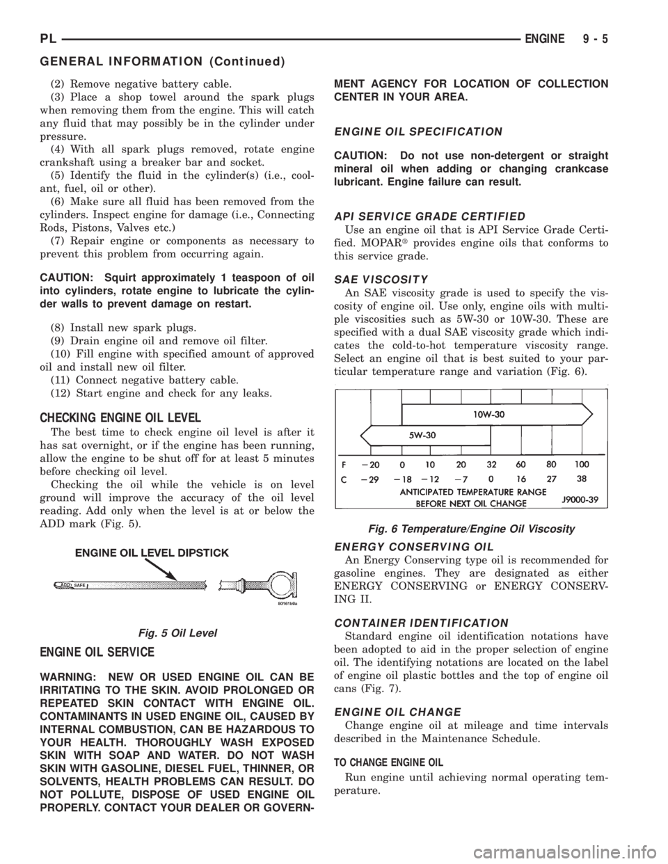
CHECKING ENGINE OIL LEVEL
The best time to check engine oil level is after it
has sat overnight, or if the engine has been running,
allow the engine to be shut off for at least 5 minutes
before checking oil level.
Checking the oil while the vehicle is on level
ground will improve the accuracy of the oil level
reading. Add only when the level is at or below the
ADD mark (Fig. 5).
ENGINE OIL SERVICE
WARNING: NEW OR USED ENGINE OIL CAN BE
IRRITATING TO THE SKIN. AVOID PROLONGED OR
REPEATED SKIN CONTACT WITH ENGINE OIL.
CONTAMINANTS IN USED ENGINE OIL, CAUSED BY
INTERNAL COMBUSTION, CAN BE HAZARDOUS TO
YOUR HEALTH. THOROUGHLY WASH EXPOSED
SKIN WITH SOAP AND WATER. DO NOT WASH
SKIN WITH GASOLINE, DIESEL FUEL, THINNER, OR
SOLVENTS, HEALTH PROBLEMS CAN RESULT. DO
NOT POLLUTE, DISPOSE OF USED ENGINE OIL
PROPERLY. CONTACT YOUR DEALER OR GOVERN-MENT AGENCY FOR LOCATION OF COLLECTION
CENTER IN YOUR AREA.
ENGINE OIL SPECIFICATION
CAUTION: Do not use non-detergent or straight
mineral oil when adding or changing crankcase
lubricant. Engine failure can result.
API SERVICE GRADE CERTIFIED
Use an engine oil that is API Service Grade Certi-
fied. MOPARtprovides engine oils that conforms to
this service grade.
SAE VISCOSITY
An SAE viscosity grade is used to specify the vis-
cosity of engine oil. Use only, engine oils with multi-
ple viscosities such as 5W-30 or 10W-30. These are
specified with a dual SAE viscosity grade which indi-
cates the cold-to-hot temperature viscosity range.
Select an engine oil that is best suited to your par-
ticular temperature range and variation (Fig. 6).
ENERGY CONSERVING OIL
An Energy Conserving type oil is recommended for
gasoline engines. They are designated as either
ENERGY CONSERVING or ENERGY CONSERV-
ING II.
CONTAINER IDENTIFICATION
Standard engine oil identification notations have
been adopted to aid in the proper selection of engine
oil. The identifying notations are located on the label
of engine oil plastic bottles and the top of engine oil
cans (Fig. 7).
ENGINE OIL CHANGE
Change engine oil at mileage and time intervals
described in the Maintenance Schedule.
TO CHANGE ENGINE OIL
Run engine until achieving normal operating tem-
perature.
Fig. 5 Oil Level
Fig. 6 Temperature/Engine Oil Viscosity
PLENGINE 9 - 5
GENERAL INFORMATION (Continued)
Page 720 of 1200

ENGINE DIAGNOSIS
INDEX
page page
DIAGNOSIS AND TESTING
CYLINDER COMBUSTION PRESSURE
LEAKAGE TEST........................ 8
CYLINDER COMPRESSION PRESSURE TEST . . 7
ENGINE DIAGNOSISÐMECHANICAL......... 11
ENGINE DIAGNOSISÐPERFORMANCE...... 10GENERAL INFORMATION.................. 7
INSPECTION (ENGINE OIL LEAKS IN
GENERAL)............................ 8
INTAKE MANIFOLD LEAKAGE DIAGNOSIS..... 7
LASH ADJUSTER (TAPPET) NOISE DIAGNOSIS.. 8
DIAGNOSIS AND TESTING
GENERAL INFORMATION
Engine diagnosis is helpful in determining the
causes of malfunctions.
These malfunctions may be classified as either
mechanical (e.g., a strange noise), or performance
(e.g., engine idles rough and stalls).
Refer to the Service DiagnosisÐMechanical Chart
and the Service DiagnosisÐPerformance Chart, for
possible causes and corrections of malfunctions. Refer
to Group 14, Fuel System, for the fuel system diag-
nosis.
Additional tests and diagnostic procedures may be
necessary for specific engine malfunctions that can-
not be isolated with the Service Diagnosis charts.
Information concerning additional tests and diagno-
sis is provided within the following:
²Cylinder Compression Pressure Test
²Cylinder Combustion Pressure Leakage Test
²Engine Cylinder Head Gasket Failure Diagnosis
²Intake Manifold Leakage Diagnosis
INTAKE MANIFOLD LEAKAGE DIAGNOSIS
An intake manifold air leak is characterized by
lower than normal manifold vacuum. Also, one or
more cylinders may not be functioning.
WARNING: USE EXTREME CAUTION WHEN THE
ENGINE IS OPERATING. DO NOT STAND IN A
DIRECT LINE WITH THE FAN. DO NOT PUT YOUR
HANDS NEAR THE PULLEYS, BELTS OR THE FAN.
DO NOT WEAR LOOSE CLOTHING.
(1) Start the engine.
(2) Spray a small stream of water (Spray Bottle) at
the suspected leak area.
(3) If a change in RPM'S, the area of the suspected
leak has been found.
(4) Repair as required.
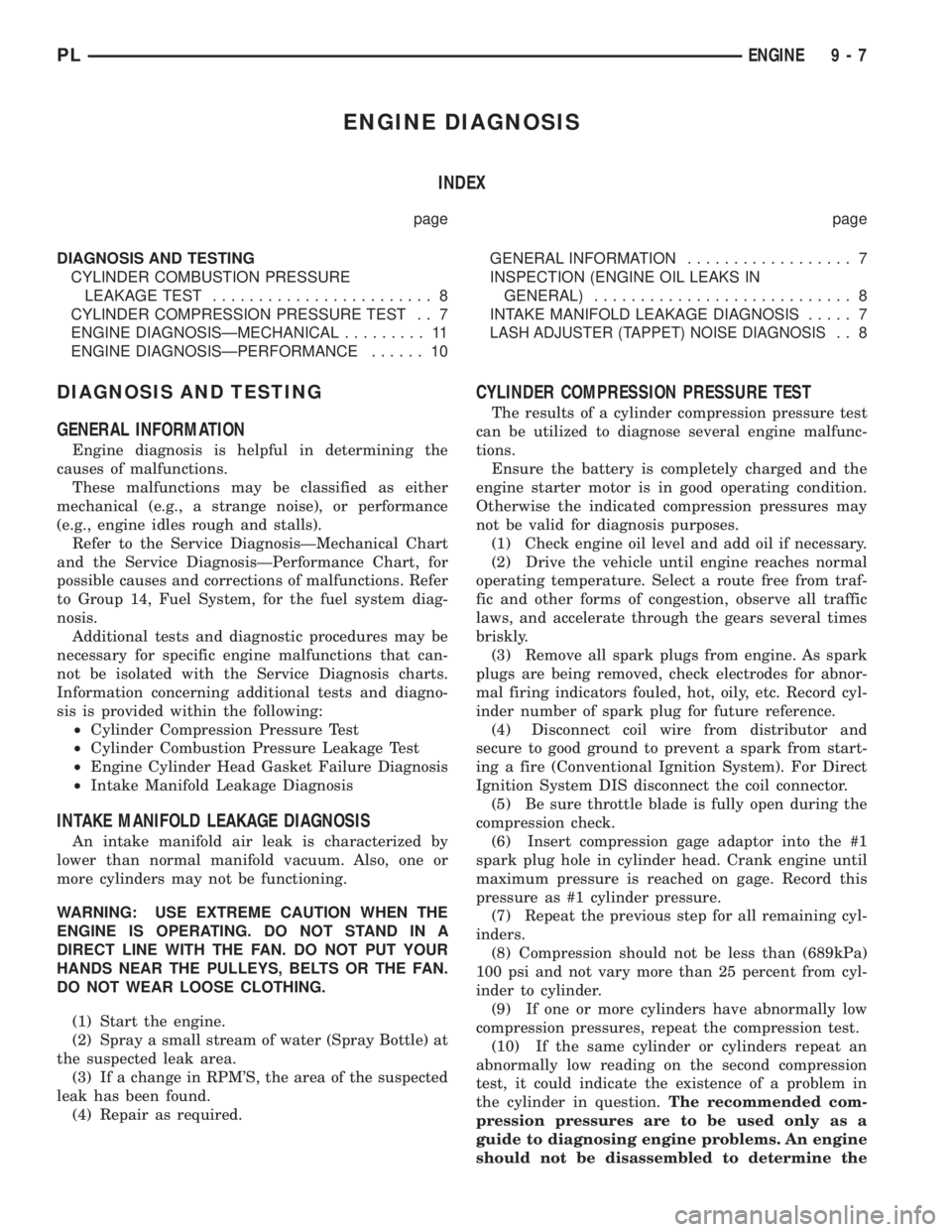
CYLINDER COMPRESSION PRESSURE TEST
The results of a cylinder compression pressure test
can be utilized to diagnose several engine malfunc-
tions.
Ensure the battery is completely charged and the
engine starter motor is in good operating condition.
Otherwise the indicated compression pressures may
not be valid for diagnosis purposes.
(1) Check engine oil level and add oil if necessary.
(2) Drive the vehicle until engine reaches normal
operating temperature. Select a route free from traf-
fic and other forms of congestion, observe all traffic
laws, and accelerate through the gears several times
briskly.
(3) Remove all spark plugs from engine. As spark
plugs are being removed, check electrodes for abnor-
mal firing indicators fouled, hot, oily, etc. Record cyl-
inder number of spark plug for future reference.
(4) Disconnect coil wire from distributor and
secure to good ground to prevent a spark from start-
ing a fire (Conventional Ignition System). For Direct
Ignition System DIS disconnect the coil connector.
(5) Be sure throttle blade is fully open during the
compression check.
(6) Insert compression gage adaptor into the #1
spark plug hole in cylinder head. Crank engine until
maximum pressure is reached on gage. Record this
pressure as #1 cylinder pressure.
(7) Repeat the previous step for all remaining cyl-
inders.
(8) Compression should not be less than (689kPa)
100 psi and not vary more than 25 percent from cyl-
inder to cylinder.
(9) If one or more cylinders have abnormally low
compression pressures, repeat the compression test.
(10) If the same cylinder or cylinders repeat an
abnormally low reading on the second compression
test, it could indicate the existence of a problem in
the cylinder in question.The recommended com-
pression pressures are to be used only as a
guide to diagnosing engine problems. An engine
should not be disassembled to determine the
PLENGINE 9 - 7