1999 DODGE NEON suspension
[x] Cancel search: suspensionPage 832 of 1200
FRAMES
INDEX
page page
REMOVAL AND INSTALLATION
FRONT SUSPENSION CROSSMEMBER....... 3
SPECIFICATIONS
STRUCTURAL DIMENSIONS................ 4TORQUE SPECIFICATIONS................ 10
REMOVAL AND INSTALLATION
FRONT SUSPENSION CROSSMEMBER
WARNING: IF SUSPENSION CROSSMEMBER IS
REPLACED DUE TO COLLISION DAMAGE, INSPECT
THE STEERING COLUMN TO STEERING GEAR
COUPLING FOR DAMAGE. REFER TO GROUP 19,
STEERING FOR INSTRUCTIONS.
Before removing front suspension crossmem-
ber, index mark location of crossmember on
frame to aid installation.
The front suspension crossmember must be prop-
erly installed to achieve design camber, caster set-
tings and wheel stagger. The crossmember can be
installed out of position on the frame rails due to its
design. Bolts and cage nuts hold the rear of the
crossmember to the frame torque boxes. Bolts and
J-nuts hold the front of the crossmember to the
frame rails. No designed in locating device is used to
position the crossmember in the vehicle. Before
removing the crossmember mark the frame torque
box around the rear mounting location to aid instal-
lation. A crossmember that is removed during service
must be installed in the same position from which it
was removed. To verify that crossmember is in the
proper position, refer to the dimensions provided.
Front end dimensions are gauged from the principal
locating point (PLP) holes located under the frame
torque boxes rearward of the front wheels. After
removal and installation of the crossmember is per-
formed, verify that front suspension alignment is
within specifications. If camber, caster settings and
wheel stagger is not within specifications, loosen and
reposition crossmember to bring suspension within
specifications. Refer to Group 2, Front Suspension
and Driveshaft for additional information.
REMOVAL
(1) Hoist and support vehicle on safety stands.
(2) Using a suitable marking device, mark the out-
line of the suspension crossmember on the frame
torque box around the rear mounting location.(3) Remove front wheels from vehicle.
(4) Remove pinch bolts holding front ball joints to
spindles.
(5) Separate ball joints from spindles.
(6) Position a suitable lifting device under the
crossmember.
(7) Remove bolts holding suspension crossmember
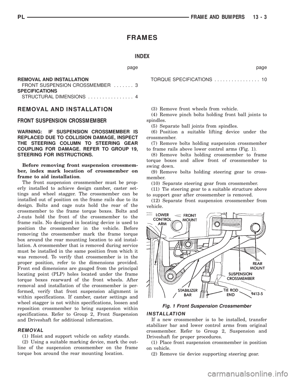
to frame rails above lower control arms (Fig. 1).
(8) Remove bolts holding crossmember to frame
torque boxes and allow front of crossmember to
swing down.
(9) Remove bolts holding steering gear to cross-
member.
(10) Separate steering gear from crossmember.
(11) Tie steering gear to a suitable structure above
to support gear after crossmember is removed.
(12) Separate front suspension crossmember from
vehicle.
INSTALLATION
If a new crossmember is to be installed, transfer
stabilizer bar and lower control arms from original
crossmember. Refer to Group 2, Suspension and
Driveshaft for proper procedures.
(1) Place front suspension crossmember in position
on vehicle.
(2) Remove tie device supporting steering gear.
Fig. 1 Front Suspension Crossmember
PLFRAME AND BUMPERS 13 - 3
Page 833 of 1200
(3) Place steering gear in position on crossmember.
(4) Install bolts to hold steering gear to crossmem-
ber.
(5) Position lifting device under the crossmember.
(6) Lift crossmember to frame rails.
(7) Engage bolts to hold crossmember rear mounts
into cage nuts in the frame torque boxes. Do not
tighten bolts.
(8) Install bolts to hold crossmember to frame rails
above lower control arms.
(9) Lower and remove lifting device.
(10) Align crossmember to index marks. Verify
that crossmember is at the specified dimensions from
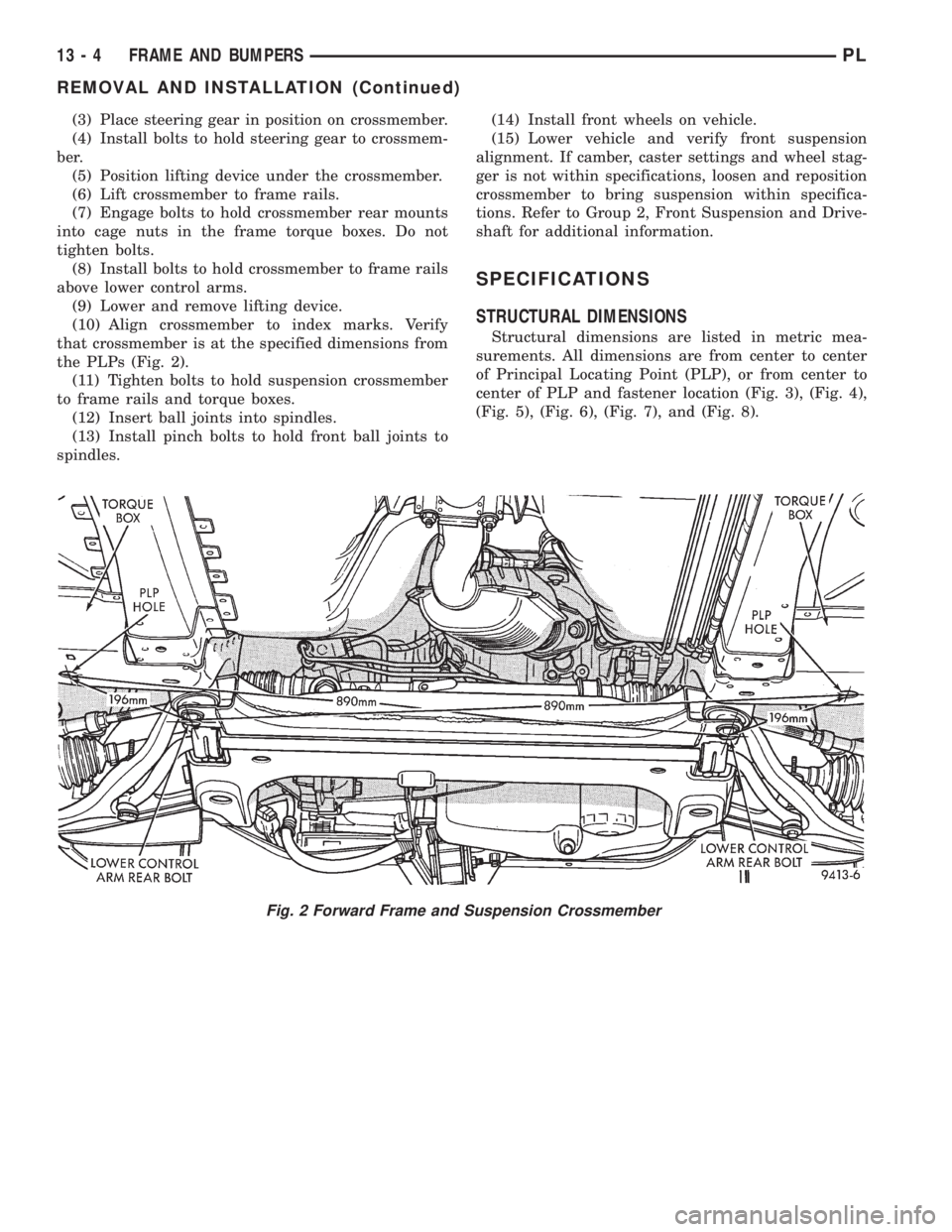
the PLPs (Fig. 2).
(11) Tighten bolts to hold suspension crossmember
to frame rails and torque boxes.
(12) Insert ball joints into spindles.
(13) Install pinch bolts to hold front ball joints to
spindles.(14) Install front wheels on vehicle.
(15) Lower vehicle and verify front suspension
alignment. If camber, caster settings and wheel stag-
ger is not within specifications, loosen and reposition
crossmember to bring suspension within specifica-
tions. Refer to Group 2, Front Suspension and Drive-
shaft for additional information.
SPECIFICATIONS
STRUCTURAL DIMENSIONS
Structural dimensions are listed in metric mea-
surements. All dimensions are from center to center
of Principal Locating Point (PLP), or from center to
center of PLP and fastener location (Fig. 3), (Fig. 4),
(Fig. 5), (Fig. 6), (Fig. 7), and (Fig. 8).
Fig. 2 Forward Frame and Suspension Crossmember
13 - 4 FRAME AND BUMPERSPL
REMOVAL AND INSTALLATION (Continued)
Page 903 of 1200
DIAGNOSIS AND TESTING
STEERING SYSTEM DIAGNOSIS CHARTS
STEERING NOISE
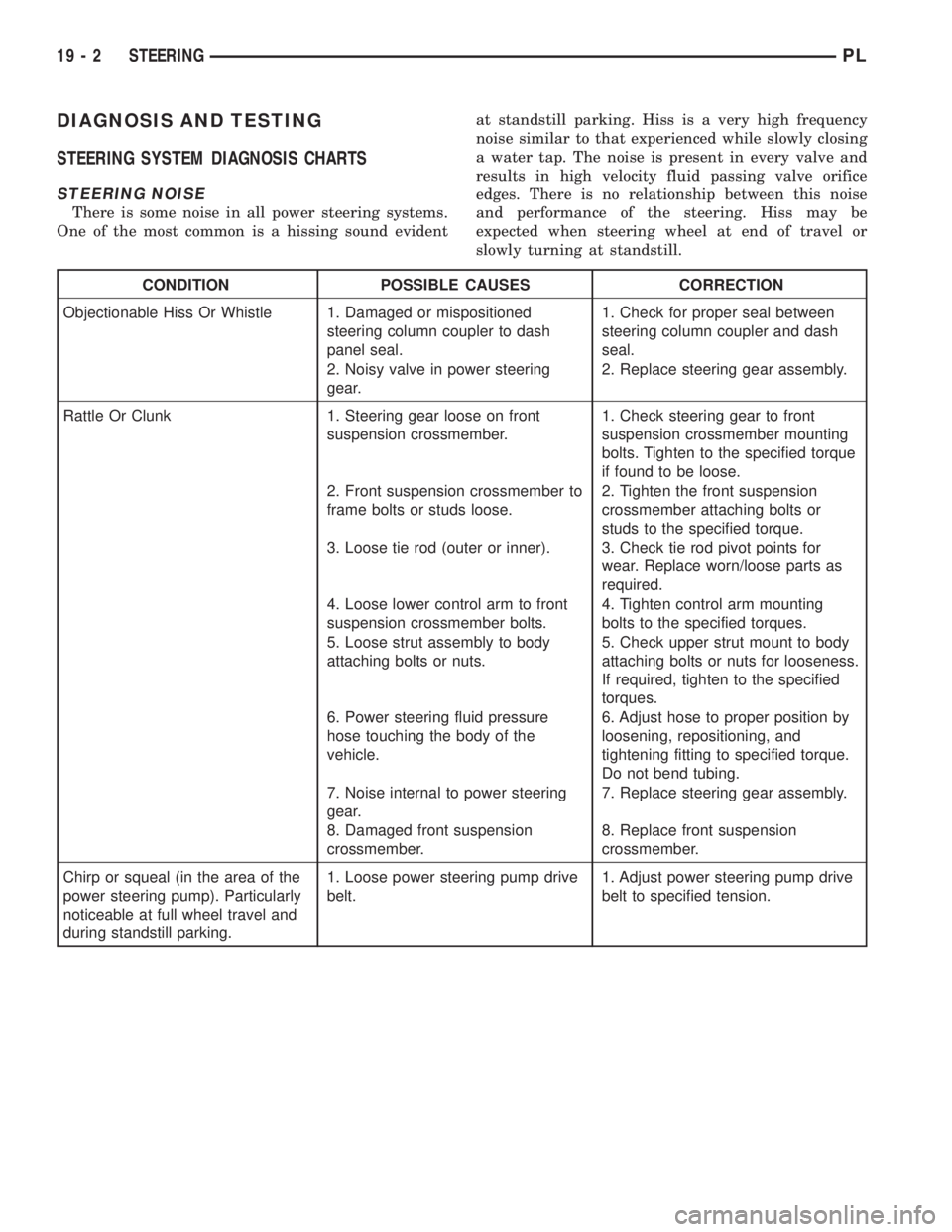
There is some noise in all power steering systems.
One of the most common is a hissing sound evidentat standstill parking. Hiss is a very high frequency
noise similar to that experienced while slowly closing
a water tap. The noise is present in every valve and
results in high velocity fluid passing valve orifice
edges. There is no relationship between this noise
and performance of the steering. Hiss may be
expected when steering wheel at end of travel or
slowly turning at standstill.
CONDITION POSSIBLE CAUSES CORRECTION
Objectionable Hiss Or Whistle 1. Damaged or mispositioned
steering column coupler to dash
panel seal.1. Check for proper seal between
steering column coupler and dash
seal.
2. Noisy valve in power steering
gear.2. Replace steering gear assembly.
Rattle Or Clunk 1. Steering gear loose on front
suspension crossmember.1. Check steering gear to front
suspension crossmember mounting
bolts. Tighten to the specified torque
if found to be loose.
2. Front suspension crossmember to
frame bolts or studs loose.2. Tighten the front suspension
crossmember attaching bolts or
studs to the specified torque.
3. Loose tie rod (outer or inner). 3. Check tie rod pivot points for
wear. Replace worn/loose parts as
required.
4. Loose lower control arm to front
suspension crossmember bolts.4. Tighten control arm mounting
bolts to the specified torques.
5. Loose strut assembly to body
attaching bolts or nuts.5. Check upper strut mount to body
attaching bolts or nuts for looseness.
If required, tighten to the specified
torques.
6. Power steering fluid pressure
hose touching the body of the
vehicle.6. Adjust hose to proper position by
loosening, repositioning, and
tightening fitting to specified torque.
Do not bend tubing.
7. Noise internal to power steering
gear.7. Replace steering gear assembly.
8. Damaged front suspension
crossmember.8. Replace front suspension
crossmember.
Chirp or squeal (in the area of the
power steering pump). Particularly
noticeable at full wheel travel and
during standstill parking.1. Loose power steering pump drive
belt.1. Adjust power steering pump drive
belt to specified tension.
19 - 2 STEERINGPL
Page 904 of 1200
CONDITION POSSIBLE CAUSES CORRECTION
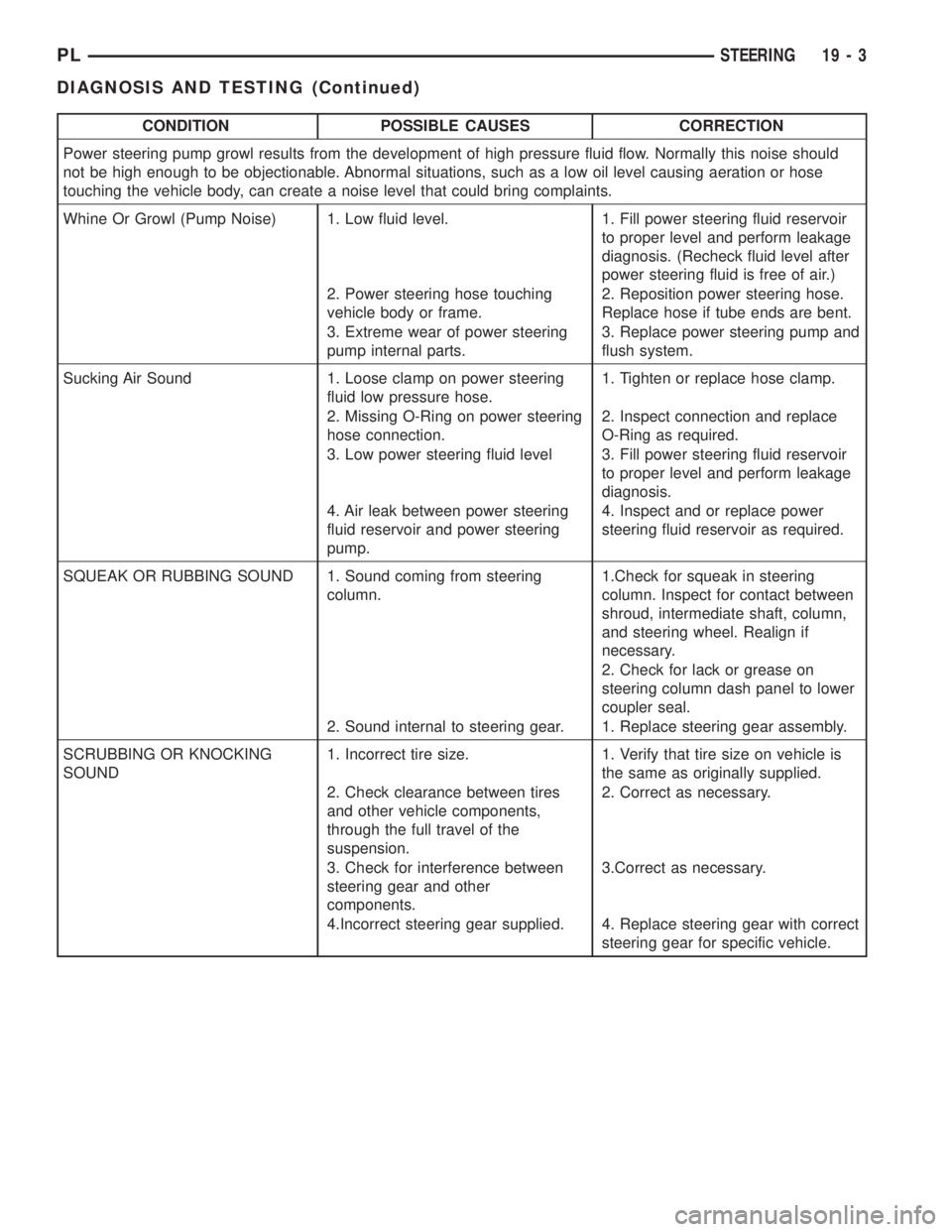
Power steering pump growl results from the development of high pressure fluid flow. Normally this noise should
not be high enough to be objectionable. Abnormal situations, such as a low oil level causing aeration or hose
touching the vehicle body, can create a noise level that could bring complaints.
Whine Or Growl (Pump Noise) 1. Low fluid level. 1. Fill power steering fluid reservoir
to proper level and perform leakage
diagnosis. (Recheck fluid level after
power steering fluid is free of air.)
2. Power steering hose touching
vehicle body or frame.2. Reposition power steering hose.
Replace hose if tube ends are bent.
3. Extreme wear of power steering
pump internal parts.3. Replace power steering pump and
flush system.
Sucking Air Sound 1. Loose clamp on power steering
fluid low pressure hose.1. Tighten or replace hose clamp.
2. Missing O-Ring on power steering
hose connection.2. Inspect connection and replace
O-Ring as required.
3. Low power steering fluid level 3. Fill power steering fluid reservoir
to proper level and perform leakage
diagnosis.
4. Air leak between power steering
fluid reservoir and power steering
pump.4. Inspect and or replace power
steering fluid reservoir as required.
SQUEAK OR RUBBING SOUND 1. Sound coming from steering
column.1.Check for squeak in steering
column. Inspect for contact between
shroud, intermediate shaft, column,
and steering wheel. Realign if
necessary.
2. Check for lack or grease on
steering column dash panel to lower
coupler seal.
2. Sound internal to steering gear. 1. Replace steering gear assembly.
SCRUBBING OR KNOCKING
SOUND1. Incorrect tire size. 1. Verify that tire size on vehicle is
the same as originally supplied.
2. Check clearance between tires
and other vehicle components,
through the full travel of the
suspension.2. Correct as necessary.
3. Check for interference between
steering gear and other
components.3.Correct as necessary.
4.Incorrect steering gear supplied. 4. Replace steering gear with correct
steering gear for specific vehicle.
PLSTEERING 19 - 3
DIAGNOSIS AND TESTING (Continued)
Page 905 of 1200
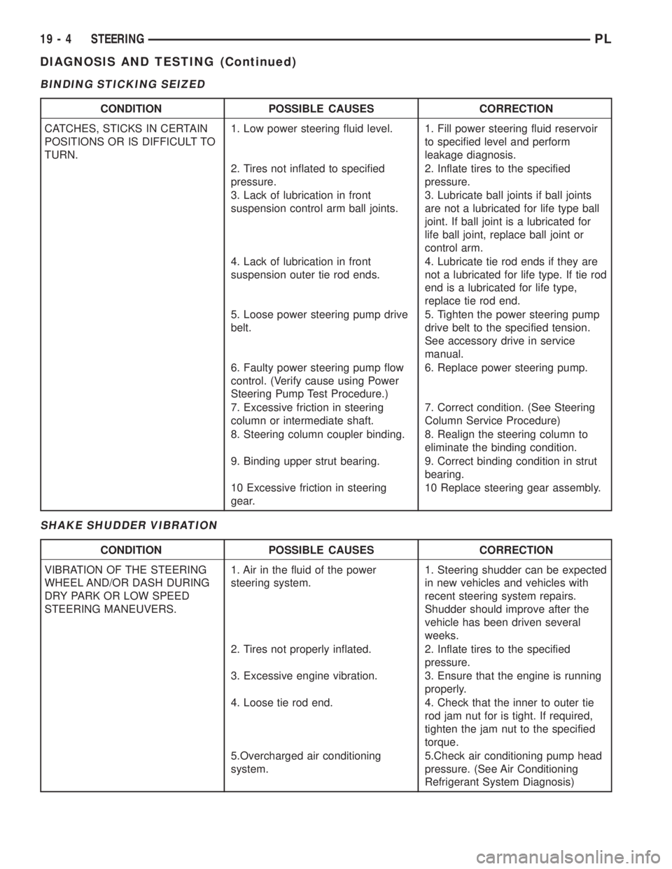
BINDING STICKING SEIZED
SHAKE SHUDDER VIBRATION
CONDITION POSSIBLE CAUSES CORRECTION
CATCHES, STICKS IN CERTAIN
POSITIONS OR IS DIFFICULT TO
TURN.1. Low power steering fluid level. 1. Fill power steering fluid reservoir
to specified level and perform
leakage diagnosis.
2. Tires not inflated to specified
pressure.2. Inflate tires to the specified
pressure.
3. Lack of lubrication in front
suspension control arm ball joints.3. Lubricate ball joints if ball joints
are not a lubricated for life type ball
joint. If ball joint is a lubricated for
life ball joint, replace ball joint or
control arm.
4. Lack of lubrication in front
suspension outer tie rod ends.4. Lubricate tie rod ends if they are
not a lubricated for life type. If tie rod
end is a lubricated for life type,
replace tie rod end.
5. Loose power steering pump drive
belt.5. Tighten the power steering pump
drive belt to the specified tension.
See accessory drive in service
manual.
6. Faulty power steering pump flow
control. (Verify cause using Power
Steering Pump Test Procedure.)6. Replace power steering pump.
7. Excessive friction in steering
column or intermediate shaft.7. Correct condition. (See Steering
Column Service Procedure)
8. Steering column coupler binding. 8. Realign the steering column to
eliminate the binding condition.
9. Binding upper strut bearing. 9. Correct binding condition in strut
bearing.
10 Excessive friction in steering
gear.10 Replace steering gear assembly.
CONDITION POSSIBLE CAUSES CORRECTION
VIBRATION OF THE STEERING
WHEEL AND/OR DASH DURING
DRY PARK OR LOW SPEED
STEERING MANEUVERS.1. Air in the fluid of the power
steering system.1. Steering shudder can be expected
in new vehicles and vehicles with
recent steering system repairs.
Shudder should improve after the
vehicle has been driven several
weeks.
2. Tires not properly inflated. 2. Inflate tires to the specified
pressure.
3. Excessive engine vibration. 3. Ensure that the engine is running
properly.
4. Loose tie rod end. 4. Check that the inner to outer tie
rod jam nut for is tight. If required,
tighten the jam nut to the specified
torque.
5.Overcharged air conditioning
system.5.Check air conditioning pump head
pressure. (See Air Conditioning
Refrigerant System Diagnosis)
19 - 4 STEERINGPL
DIAGNOSIS AND TESTING (Continued)
Page 907 of 1200
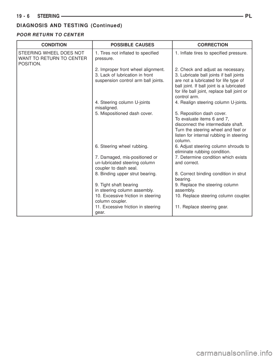
POOR RETURN TO CENTER
CONDITION POSSIBLE CAUSES CORRECTION
STEERING WHEEL DOES NOT
WANT TO RETURN TO CENTER
POSITION.1. Tires not inflated to specified
pressure.1. Inflate tires to specified pressure.
2. Improper front wheel alignment. 2. Check and adjust as necessary.
3. Lack of lubrication in front
suspension control arm ball joints.3. Lubricate ball joints if ball joints
are not a lubricated for life type of
ball joint. If ball joint is a lubricated
for life ball joint, replace ball joint or
control arm.
4. Steering column U-joints
misaligned.4. Realign steering column U-joints.
5. Mispositioned dash cover. 5. Reposition dash cover.
To evaluate items 6 and 7,
disconnect the intermediate shaft.
Turn the steering wheel and feel or
listen for internal rubbing in steering
column.
6. Steering wheel rubbing. 6. Adjust steering column shrouds to
eliminate rubbing condition.
7. Damaged, mis-positioned or
un-lubricated steering column
coupler to dash seal.7. Determine condition which exists
and correct.
8. Binding upper strut bearing. 8. Correct binding condition in strut
bearing.
9. Tight shaft bearing
in steering column assembly.9. Replace the steering column
assembly.
10. Excessive friction in steering
column coupler.10. Replace steering column coupler.
11. Excessive friction in steering
gear.11. Replace steering gear.
19 - 6 STEERINGPL
DIAGNOSIS AND TESTING (Continued)
Page 908 of 1200
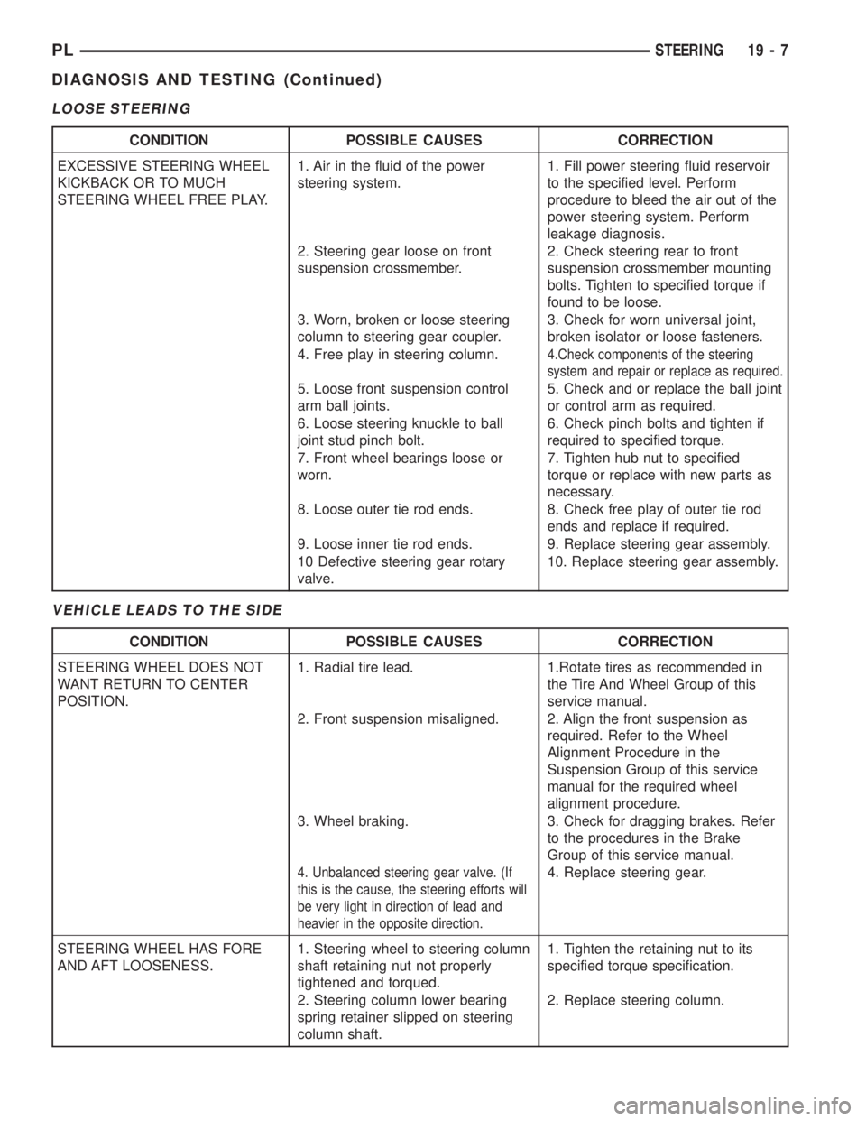
LOOSE STEERING
VEHICLE LEADS TO THE SIDE
CONDITION POSSIBLE CAUSES CORRECTION
EXCESSIVE STEERING WHEEL
KICKBACK OR TO MUCH
STEERING WHEEL FREE PLAY.1. Air in the fluid of the power
steering system.1. Fill power steering fluid reservoir
to the specified level. Perform
procedure to bleed the air out of the
power steering system. Perform
leakage diagnosis.
2. Steering gear loose on front
suspension crossmember.2. Check steering rear to front
suspension crossmember mounting
bolts. Tighten to specified torque if
found to be loose.
3. Worn, broken or loose steering
column to steering gear coupler.3. Check for worn universal joint,
broken isolator or loose fasteners.
4. Free play in steering column.
4.Check components of the steering
system and repair or replace as required.
5. Loose front suspension control
arm ball joints.5. Check and or replace the ball joint
or control arm as required.
6. Loose steering knuckle to ball
joint stud pinch bolt.6. Check pinch bolts and tighten if
required to specified torque.
7. Front wheel bearings loose or
worn.7. Tighten hub nut to specified
torque or replace with new parts as
necessary.
8. Loose outer tie rod ends. 8. Check free play of outer tie rod
ends and replace if required.
9. Loose inner tie rod ends. 9. Replace steering gear assembly.
10 Defective steering gear rotary
valve.10. Replace steering gear assembly.
CONDITION POSSIBLE CAUSES CORRECTION
STEERING WHEEL DOES NOT
WANT RETURN TO CENTER
POSITION.1. Radial tire lead. 1.Rotate tires as recommended in
the Tire And Wheel Group of this
service manual.
2. Front suspension misaligned. 2. Align the front suspension as
required. Refer to the Wheel
Alignment Procedure in the
Suspension Group of this service
manual for the required wheel
alignment procedure.
3. Wheel braking. 3. Check for dragging brakes. Refer
to the procedures in the Brake
Group of this service manual.
4. Unbalanced steering gear valve. (If
this is the cause, the steering efforts will
be very light in direction of lead and
heavier in the opposite direction.4. Replace steering gear.
STEERING WHEEL HAS FORE
AND AFT LOOSENESS.1. Steering wheel to steering column
shaft retaining nut not properly
tightened and torqued.1. Tighten the retaining nut to its
specified torque specification.
2. Steering column lower bearing
spring retainer slipped on steering
column shaft.2. Replace steering column.
PLSTEERING 19 - 7
DIAGNOSIS AND TESTING (Continued)
Page 914 of 1200
REMOVE
CAUTION: When removing and installing the
power steering pressure switch, the use of a 7/8
inch deep well socket is required. The deep well
socket will prevent damage to the plastic, electrical
connector area, of the power steering pressure
switch.
(1) Disconnect negative battery cable from the neg-
ative post of the battery. Be sure cable is isolated
from negative post on battery.
(2) Raise vehicle.
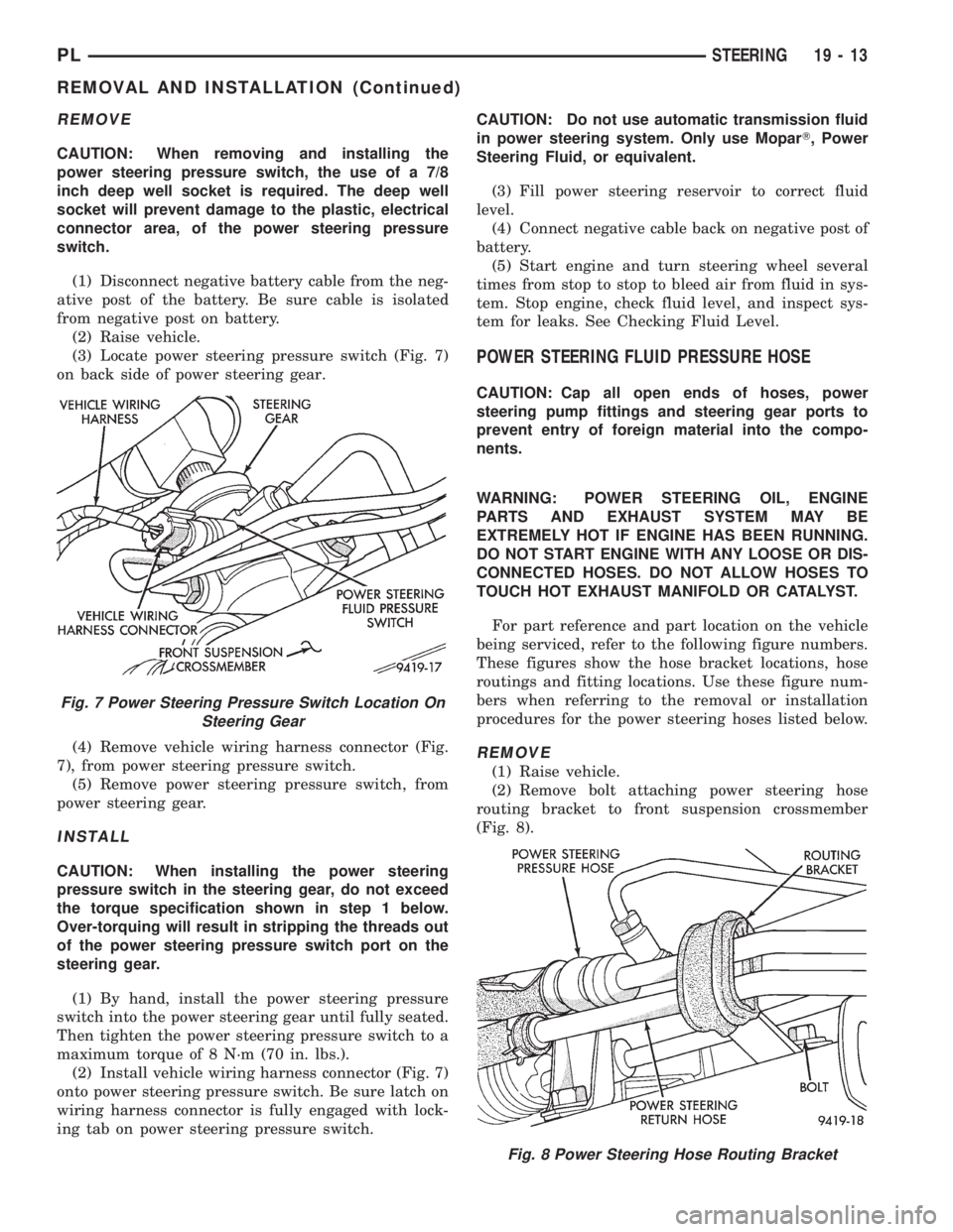
(3) Locate power steering pressure switch (Fig. 7)
on back side of power steering gear.
(4) Remove vehicle wiring harness connector (Fig.
7), from power steering pressure switch.
(5) Remove power steering pressure switch, from
power steering gear.
INSTALL
CAUTION: When installing the power steering
pressure switch in the steering gear, do not exceed
the torque specification shown in step 1 below.
Over-torquing will result in stripping the threads out
of the power steering pressure switch port on the
steering gear.
(1) By hand, install the power steering pressure
switch into the power steering gear until fully seated.
Then tighten the power steering pressure switch to a
maximum torque of 8 N´m (70 in. lbs.).
(2) Install vehicle wiring harness connector (Fig. 7)
onto power steering pressure switch. Be sure latch on
wiring harness connector is fully engaged with lock-
ing tab on power steering pressure switch.CAUTION: Do not use automatic transmission fluid
in power steering system. Only use MoparT, Power
Steering Fluid, or equivalent.
(3) Fill power steering reservoir to correct fluid
level.
(4) Connect negative cable back on negative post of
battery.
(5) Start engine and turn steering wheel several
times from stop to stop to bleed air from fluid in sys-
tem. Stop engine, check fluid level, and inspect sys-
tem for leaks. See Checking Fluid Level.
POWER STEERING FLUID PRESSURE HOSE
CAUTION: Cap all open ends of hoses, power
steering pump fittings and steering gear ports to
prevent entry of foreign material into the compo-
nents.
WARNING: POWER STEERING OIL, ENGINE
PARTS AND EXHAUST SYSTEM MAY BE
EXTREMELY HOT IF ENGINE HAS BEEN RUNNING.
DO NOT START ENGINE WITH ANY LOOSE OR DIS-
CONNECTED HOSES. DO NOT ALLOW HOSES TO
TOUCH HOT EXHAUST MANIFOLD OR CATALYST.
For part reference and part location on the vehicle
being serviced, refer to the following figure numbers.
These figures show the hose bracket locations, hose
routings and fitting locations. Use these figure num-
bers when referring to the removal or installation
procedures for the power steering hoses listed below.
REMOVE
(1) Raise vehicle.
(2) Remove bolt attaching power steering hose
routing bracket to front suspension crossmember
(Fig. 8).
Fig. 7 Power Steering Pressure Switch Location On
Steering Gear
Fig. 8 Power Steering Hose Routing Bracket
PLSTEERING 19 - 13
REMOVAL AND INSTALLATION (Continued)