Page 937 of 1200

STEERING GEAR TO STEERING COLUMN
COUPLING
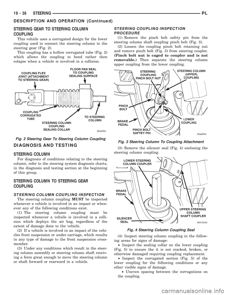
This vehicle uses a corrugated design for the lower
coupling used to connect the steering column to the
steering gear (Fig. 2).
This coupling has a hollow corrugated tube (Fig. 2)
which allows the coupling to bend rather then
colapse when a vehicle is involved in a collision.
DIAGNOSIS AND TESTING
STEERING COLUMN
For diagnosis of conditions relating to the steering
column, refer to the steering system diagnosis charts,
in the diagnosis and testing section at the beginning
of this group.
STEERING COLUMN TO STEERING GEAR
COUPLING
STEERING COLUMN COUPLING INSPECTION
The steering column couplingMUSTbe inspected
whenever a vehicle is involved in an impact or when-
ever any of the following conditions exist.
(1) The steering column coupling must be
inspected whenever a vehicle is involved in a colli-
sion which deploys the air bag, regardless of the
extent of damage done to the vehicle.
(2) If a vehicle is involved in an impact of the vehi-
cles front suspension or under carriage, which results
in any type of damage to the front suspension cross-
member.
(3) Under any conditions which result in the steer-
ing column assembly or steering column shaft receiv-
ing a force great enough to move the steering column
or shaft forward or rearward in a vehicle.
STEERING COUPLING INSPECTION
PROCEDURE
(1) Remove the pinch bolt safety pin from the
steering column shaft coupling pinch bolt (Fig. 3).
(2) Loosen the coupling pinch bolt retaining nut
and remove pinch bolt (Fig. 3) from steering coupler.
(Pinch bolt nut is caged to coupler and is not
removable.)Then separate the steering column
upper coupling from the lower coupling.
(3) Remove the silencer seal (Fig. 4) enclosing the
steering column coupling.
(4) Inspect steering column coupling in the follow-
ing areas for signs of damage:
²Inspect the sealing collar on the lower coupling
(Fig. 5) to ensure the it is not cracked, broken, or
otherwise damaged requiring coupling replacement.
²Inspect the corrugated section (Fig. 5) of the
lower coupling for the following conditions or any
other visible signs of damage.
²Uneven spacing between the corrugations on
the coupling.
Fig. 2 Steering Gear To Steering Column CouplingFig. 3 Steering Column To Coupling Attachment
Fig. 4 Steering Column Coupling Seal
19 - 36 STEERINGPL
DESCRIPTION AND OPERATION (Continued)
Page 952 of 1200

CAUTION: Pry up with equal force on both sides of
shifter cable isolator bushing to avoid damaging
cable isolator bushing.
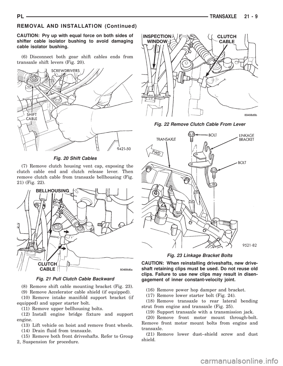
(6) Disconnect both gear shift cables ends from
transaxle shift levers (Fig. 20).
(7) Remove clutch housing vent cap, exposing the
clutch cable end and clutch release lever. Then
remove clutch cable from transaxle bellhousing (Fig.
21) (Fig. 22).
(8) Remove shift cable mounting bracket (Fig. 23).
(9) Remove Accelerator cable shield (if equipped).
(10) Remove intake manifold support bracket (if
equipped) and upper starter bolt.
(11) Remove upper bellhousing bolts.
(12) Install engine bridge fixture and support
engine.
(13) Lift vehicle on hoist and remove front wheels.
(14) Drain fluid from transaxle.
(15) Remove both front driveshafts. Refer to Group
2, Suspension for procedure.CAUTION: When reinstalling driveshafts, new drive-
shaft retaining clips must be used. Do not reuse old
clips. Failure to use new clips may result in disen-
gagement of inner constant-velocity joint.
(16) Remove power hop damper and bracket.
(17) Remove lower starter bolt (Fig. 24).
(18) Remove transaxle to rear lateral bending
strut from engine and transaxle (Fig. 25).
(19) Support transaxle with a transmission jack.
(20) Remove front motor mount through-bolt.
Remove front motor mount bolts from engine and
transaxle.
(21) Remove lower dust±shield screw and dust
shield.
Fig. 20 Shift Cables
Fig. 21 Pull Clutch Cable Backward
Fig. 22 Remove Clutch Cable From Lever
Fig. 23 Linkage Bracket Bolts
PLTRANSAXLE 21 - 9
REMOVAL AND INSTALLATION (Continued)
Page 1008 of 1200
(11) Install engine bridge fixture and support
engine (Fig. 27).
(12) Lift vehicle on hoist and remove front wheels.(13) Remove both front driveshafts. Refer to Group
2, Suspension for procedure.
Fig. 22 Gearshift Cable
Fig. 23 Shifter Cable Bracket
Fig. 24 Bracket Removal
Fig. 25 Cooler Lines
Fig. 26 Starter and Bellhousing Bolts
Fig. 27 Engine Bridge Fixture
PLTRANSAXLE 21 - 65
REMOVAL AND INSTALLATION (Continued)
Page 1070 of 1200

weather temperature varies widely. Tire pressure will
decrease when the outdoor temperature drops.
Inflation pressures specified on the placard are
always the cold inflation pressure of the tire. Cold
inflation pressure is obtained after the vehicle has
not been operated for at least 3 hours, or the vehicle
is driven less than one mile after being inoperative
for 3 hours. Tire inflation pressures may increase
from 2 to 6 pounds per square inch (psi) during oper-
ation. Do not reduce this normal pressure build-up.
WARNING: OVER OR UNDER INFLATED TIRES
CAN AFFECT VEHICLE HANDLING. THE TIRE CAN
FAIL SUDDENLY, RESULTING IN LOSS OF VEHICLE
CONTROL.
TIRE PRESSURE FOR HIGH SPEED OPERATION
Chrysler Corporation advocates driving at safe
speeds within posted speed limits. Where speed lim-
its allow the vehicle to be driven at high speeds, cor-
rect tire inflation pressure is very important. For
speeds up to and including 120 km/h (75 mph), tires
must be inflated to the pressures shown on the tire
placard. For continuous speeds in excess of 120 km/h
(75 mph), tires must be inflated to the maximum
pressure specified on the tire sidewall.
Vehicles loaded to the maximum capacity should
not be driven at continuous speeds above 75 mph
(120 km/h).
For emergency vehicles that are driven at speeds
over 90 mph (144 km/h), special high speed tires
must be used. Consult tire manufacturer for correct
inflation pressure recommendations.
REPLACEMENT TIRES
The original equipment tires provide a proper bal-
ance of many characteristics such as:
²Ride
²Noise
²Handling
²Durability
²Tread life
²Traction
²Rolling resistance
²Speed capability
It is recommend that tires equivalent to the origi-
nal equipment tires be used when replacement is
needed.
Failure to use equivalent replacement tires may
adversely affect the safety and handling of the vehi-
cle.
The use of oversize tires not listed in the specifica-
tion charts may cause interference with vehicle com-
ponents. Under extremes of suspension and steering
travel, interference with vehicle components may
cause tire damage.WARNING: FAILURE TO EQUIP THE VEHICLE WITH
TIRES HAVING ADEQUATE SPEED CAPABILITY
CAN RESULT IN SUDDEN TIRE FAILURE.
DIAGNOSIS AND TESTING
PRESSURE GAUGES
A quality air pressure gauge is recommended to
check tire pressure. After checking the air pressure,
replace valve cap finger tight.
TREAD WEAR INDICATORS
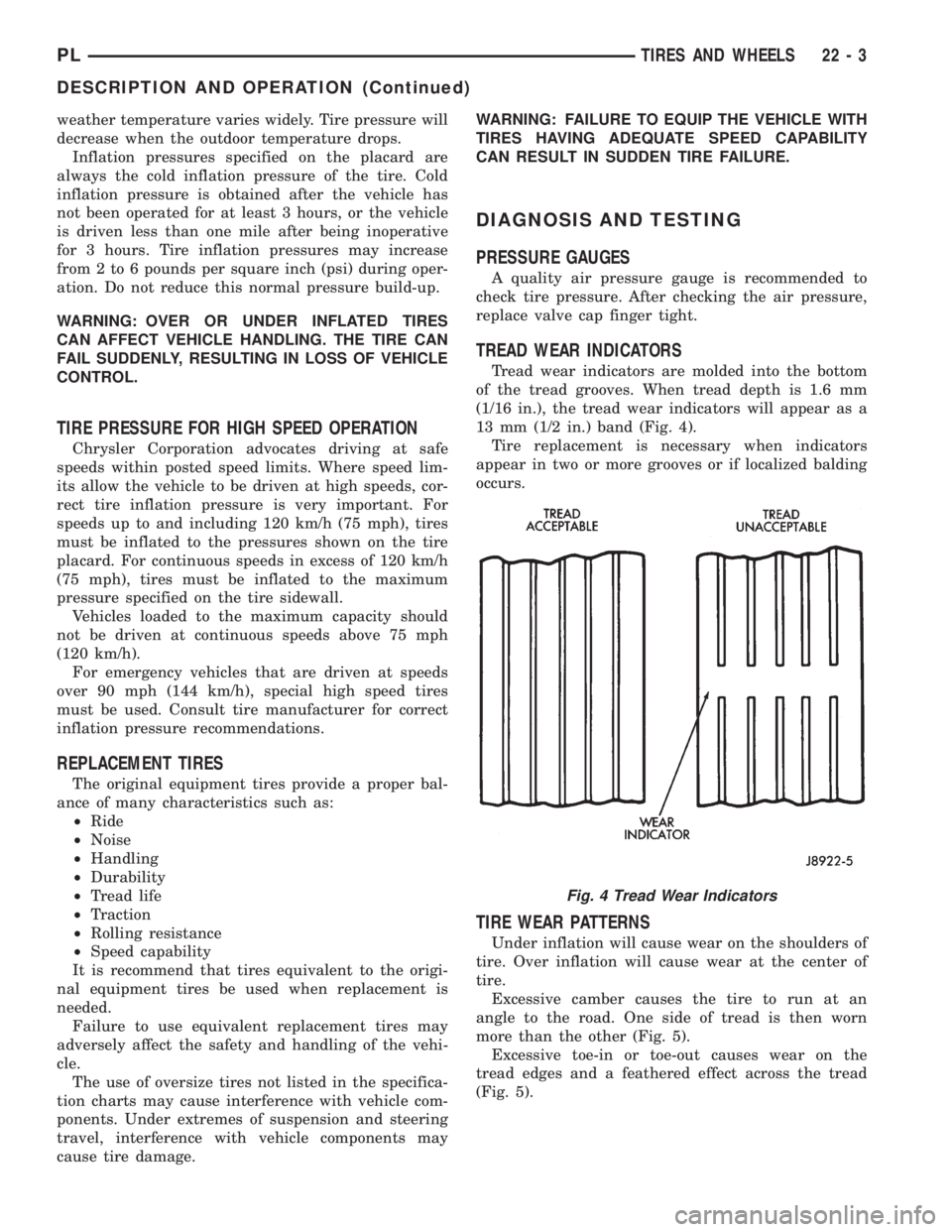
Tread wear indicators are molded into the bottom
of the tread grooves. When tread depth is 1.6 mm
(1/16 in.), the tread wear indicators will appear as a
13 mm (1/2 in.) band (Fig. 4).
Tire replacement is necessary when indicators
appear in two or more grooves or if localized balding
occurs.
TIRE WEAR PATTERNS
Under inflation will cause wear on the shoulders of
tire. Over inflation will cause wear at the center of
tire.
Excessive camber causes the tire to run at an
angle to the road. One side of tread is then worn
more than the other (Fig. 5).
Excessive toe-in or toe-out causes wear on the
tread edges and a feathered effect across the tread
(Fig. 5).
Fig. 4 Tread Wear Indicators
PLTIRES AND WHEELS 22 - 3
DESCRIPTION AND OPERATION (Continued)
Page 1200 of 1200

GROUP TAB LOCATOR
INIntroduction
INaIntroduction
0Lubrication and Maintenance
2Suspension
3Differential and Driveline
5Brakes
6Clutch
6aClutch
7Cooling
8ABattery
8BStarting
8CCharging System
8CaCharging System
8DIgnition System
8EInstrument Panel and Systems
8EaInstrument Panel and Systems
8FAudio System
8GHorns
8HVehicle Speed Control System
8HaVehicle Speed Control System
8JTurn Signal and Flashers
8KWindshield Wipers and Washers
8KaWindshield Wipers and Washers
8LLamps
8LaLamps
8MRestraint System
8NElectrically Heated Systems
8NaElectrically Heated Systems
8PPower Door Locks
8QaImmobilizer System
8SPower Windows
8TPower Mirrors
8TaPower Mirrors
8UChime Warning/Reminder System
8WWiring Diagrams - LHD and RHD
9Engine
9aEngine
11Exhaust System and Intake Manifold
11aExhaust System and Intake Manifold
13Frame and Bumpers
13aFrame and Bumpers
14Fuel System
14aFuel System - 1.8L Engine
19Steering
19aSteering
21Transaxle
21aTransaxle
22Tires and Wheels
23Body
24Heating and Air Conditioning
25Emission Control Systems
25aEmission Control System - 1.8L Engine