1999 DODGE NEON suspension
[x] Cancel search: suspensionPage 62 of 1200
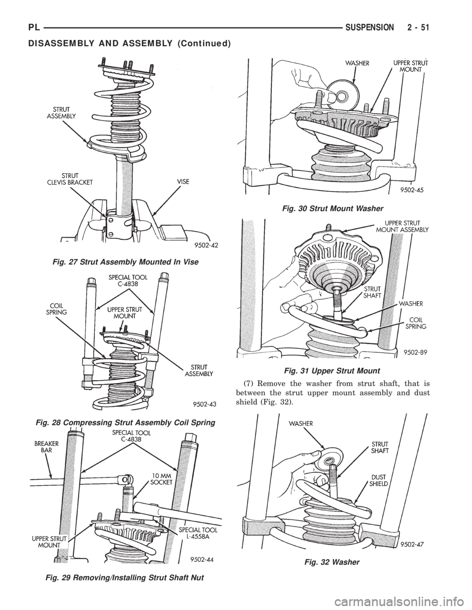
(7) Remove the washer from strut shaft, that is
between the strut upper mount assembly and dust
shield (Fig. 32).
Fig. 27 Strut Assembly Mounted In Vise
Fig. 28 Compressing Strut Assembly Coil Spring
Fig. 29 Removing/Installing Strut Shaft Nut
Fig. 30 Strut Mount Washer
Fig. 31 Upper Strut Mount
Fig. 32 Washer
PLSUSPENSION 2 - 51
DISASSEMBLY AND ASSEMBLY (Continued)
Page 63 of 1200
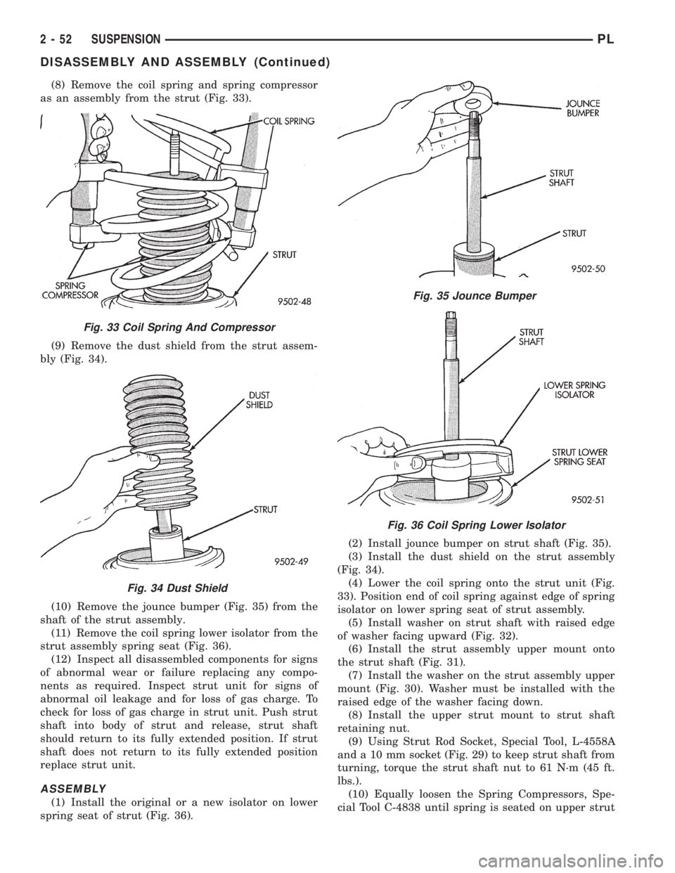
(8) Remove the coil spring and spring compressor
as an assembly from the strut (Fig. 33).
(9) Remove the dust shield from the strut assem-
bly (Fig. 34).
(10) Remove the jounce bumper (Fig. 35) from the
shaft of the strut assembly.
(11) Remove the coil spring lower isolator from the
strut assembly spring seat (Fig. 36).
(12) Inspect all disassembled components for signs
of abnormal wear or failure replacing any compo-
nents as required. Inspect strut unit for signs of
abnormal oil leakage and for loss of gas charge. To
check for loss of gas charge in strut unit. Push strut
shaft into body of strut and release, strut shaft
should return to its fully extended position. If strut
shaft does not return to its fully extended position
replace strut unit.
ASSEMBLY
(1) Install the original or a new isolator on lower
spring seat of strut (Fig. 36).(2) Install jounce bumper on strut shaft (Fig. 35).
(3) Install the dust shield on the strut assembly
(Fig. 34).
(4) Lower the coil spring onto the strut unit (Fig.
33). Position end of coil spring against edge of spring
isolator on lower spring seat of strut assembly.
(5) Install washer on strut shaft with raised edge
of washer facing upward (Fig. 32).
(6) Install the strut assembly upper mount onto
the strut shaft (Fig. 31).
(7) Install the washer on the strut assembly upper
mount (Fig. 30). Washer must be installed with the
raised edge of the washer facing down.
(8) Install the upper strut mount to strut shaft
retaining nut.
(9) Using Strut Rod Socket, Special Tool, L-4558A
and a 10 mm socket (Fig. 29) to keep strut shaft from
turning, torque the strut shaft nut to 61 N´m (45 ft.
lbs.).
(10) Equally loosen the Spring Compressors, Spe-
cial Tool C-4838 until spring is seated on upper strut
Fig. 33 Coil Spring And Compressor
Fig. 34 Dust Shield
Fig. 35 Jounce Bumper
Fig. 36 Coil Spring Lower Isolator
2 - 52 SUSPENSIONPL
DISASSEMBLY AND ASSEMBLY (Continued)
Page 64 of 1200
mount and all tension is relieved from the spring
compressors.
(11) Install the strut assembly back into the vehi-
cle. Refer to Strut Assembly Removal in Servicing
Rear Struts in this section of the service manual.
(12) Check and reset rear wheel TOE to specifica-
tions if required.
STABILIZER BAR BUSHINGS
(1) If stabilizer bar to frame rail bushings require
replacement at time of inspection, install new bush-
ings before installing stabilizer bar. Bushings are
replaced by opening slit on bushings and peeling
them off stabilizer bar. Install new bushings on sta-
bilizer bar, by spreading bushing at slit and forcing
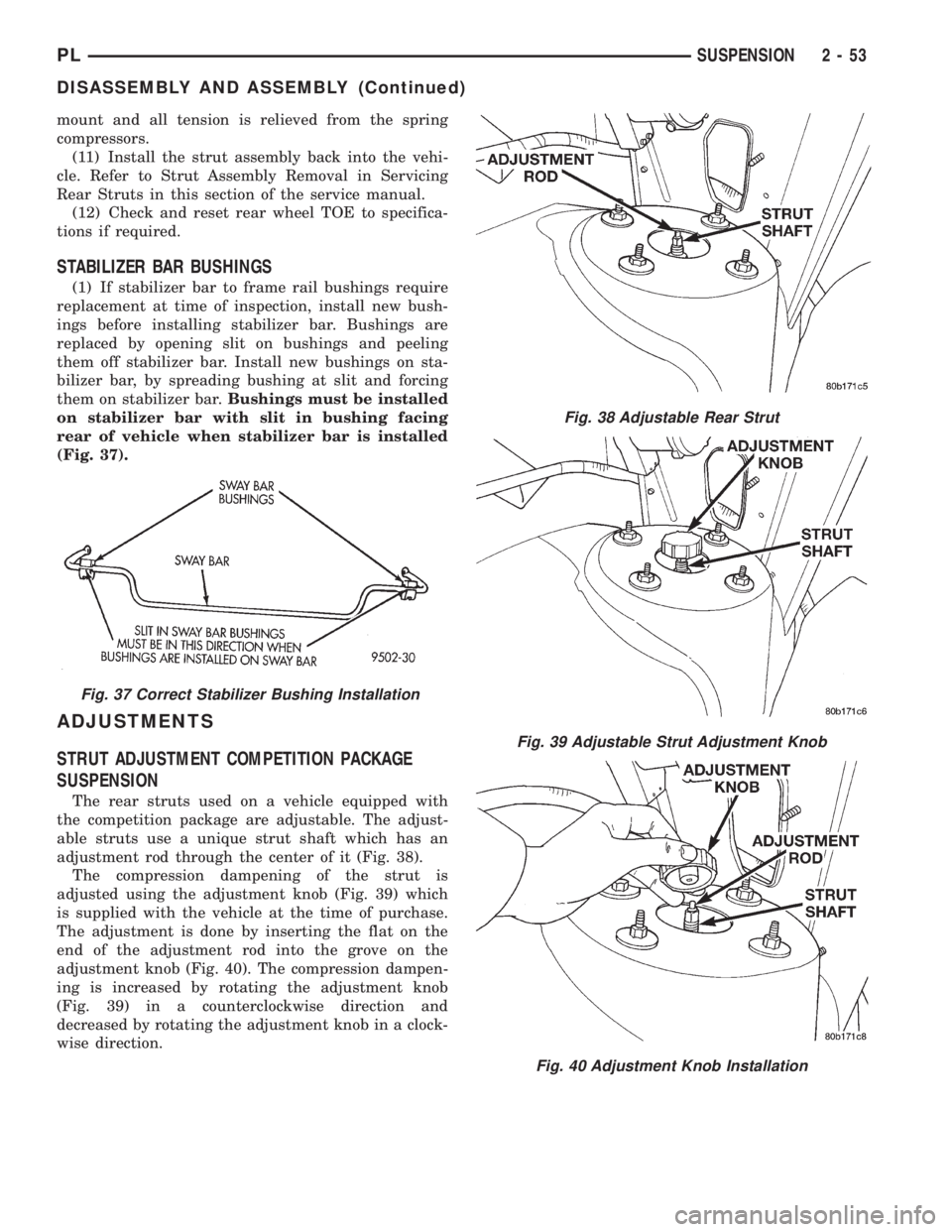
them on stabilizer bar.Bushings must be installed
on stabilizer bar with slit in bushing facing
rear of vehicle when stabilizer bar is installed
(Fig. 37).
ADJUSTMENTS
STRUT ADJUSTMENT COMPETITION PACKAGE
SUSPENSION
The rear struts used on a vehicle equipped with
the competition package are adjustable. The adjust-
able struts use a unique strut shaft which has an
adjustment rod through the center of it (Fig. 38).
The compression dampening of the strut is
adjusted using the adjustment knob (Fig. 39) which
is supplied with the vehicle at the time of purchase.
The adjustment is done by inserting the flat on the
end of the adjustment rod into the grove on the
adjustment knob (Fig. 40). The compression dampen-
ing is increased by rotating the adjustment knob
(Fig. 39) in a counterclockwise direction and
decreased by rotating the adjustment knob in a clock-
wise direction.
Fig. 37 Correct Stabilizer Bushing Installation
Fig. 38 Adjustable Rear Strut
Fig. 39 Adjustable Strut Adjustment Knob
Fig. 40 Adjustment Knob Installation
PLSUSPENSION 2 - 53
DISASSEMBLY AND ASSEMBLY (Continued)
Page 65 of 1200
SPECIFICATIONS
REAR SUSPENSION FASTENER TORQUE
SPECIFICATIONS
DESCRIPTION TORQUE
STRUT ASSEMBLY:
To Body Attaching Nuts.......34N´m(300 in. lbs.)
Clevis Bracket To Knuckle
Nut/Bolt..................95N´m(70ft.lbs.)
Strut Assembly Shaft Nut.......75N´m(55ft.lbs.)
BRAKE SUPPORT PLATE:
To Knuckle Bolts..............68N´m(50ft.lbs.)
STABILIZER BAR:
Bushing Retainer To
Frame Bolt...............34N´m(300 in. lbs.)
To Strut Attaching Link Nut . . .34 N´m (300 in. lbs.)
TENSION STRUT:
Shaft Nut...................95N´m(70ft.lbs.)
Bracket To Body Attaching
Bolts.....................95N´m(70ft.lbs.)
LATERAL LINK:
Attaching Nut................95N´m(70ft.lbs.)
DISC BRAKE CALIPER:
To Adapter Mounting Bolt......22N´m(16ft.lbs.)
Brake Hose To Caliper
Mounting Bolt..............45N´m(35ft.lbs.)
Adapter To Knuckle
Mounting Bolt..............68N´m(50ft.lbs.)
BRAKE HOSE:
Bracket Mounting Bolt........23N´m(17ft.lbs.)
HUB AND BEARING:
To Knuckle Retaining Nut.....216 N´m (160 ft. lbs.)
Wheel Stud Lug Nuts
(All Wheel Types). . . .109-150 N´m (80-110 ft. lbs.)
SPECIAL TOOLS
REAR SUSPENSION
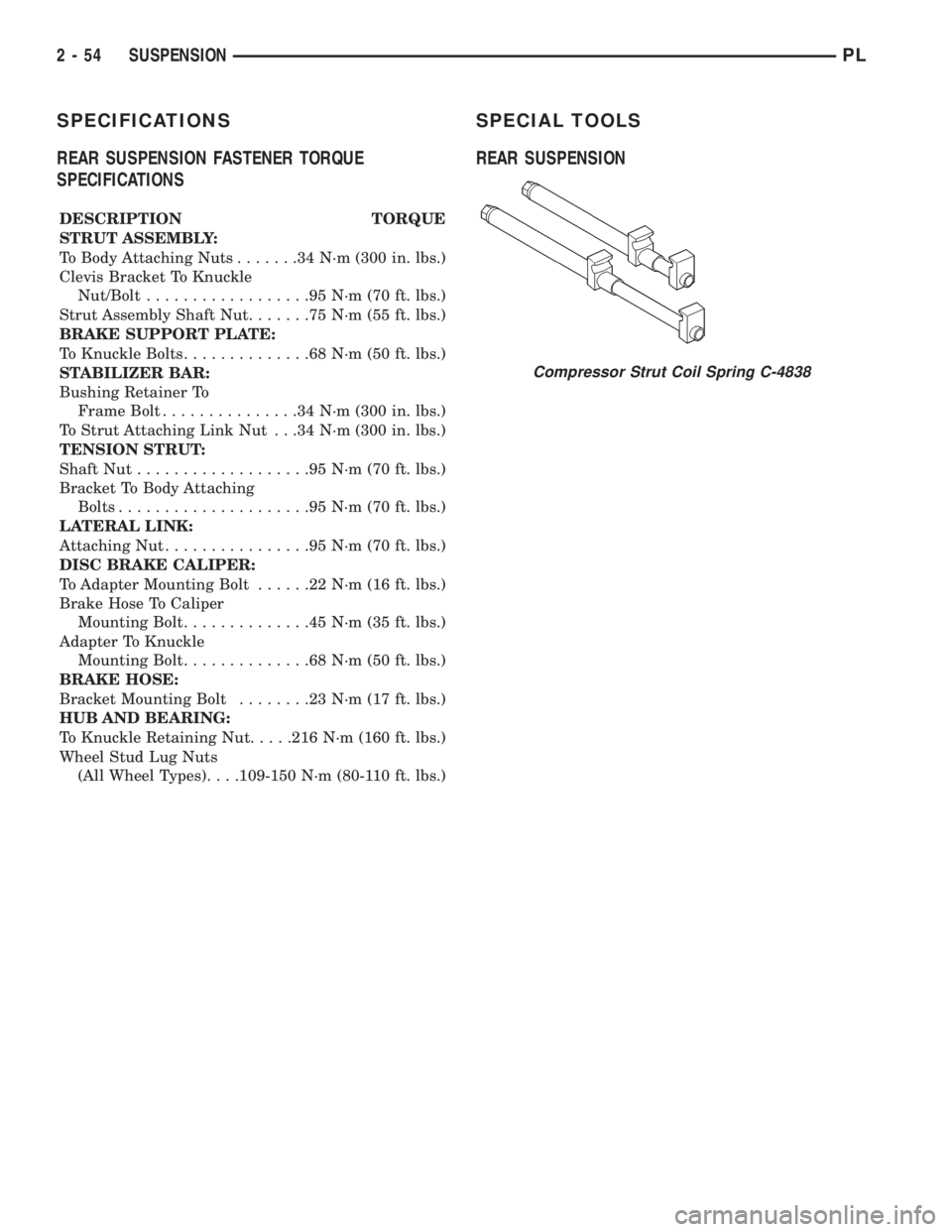
Compressor Strut Coil Spring C-4838
2 - 54 SUSPENSIONPL
Page 85 of 1200
REAR DISC BRAKES
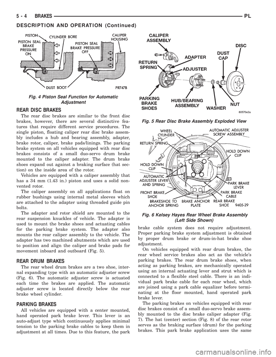
The rear disc brakes are similar to the front disc
brakes, however, there are several distinctive fea-
tures that require different service procedures. The
single piston, floating caliper rear disc brake assem-
bly includes a hub and bearing assembly, adapter,
brake rotor, caliper, brake pads/linings. The parking
brake system on all vehicles equipped with rear disc
brakes consists of a small duo-servo drum brake
mounted to the caliper adapter. The drum brake
shoes expand out against a braking surface (hat sec-
tion) on the inside area of the rotor.
Vehicles are equipped with a caliper assembly that
has a 34 mm (1.43 in.) piston and uses a solid non-
vented rotor.
The caliper assembly on all applications float on
rubber bushings using internal metal sleeves which
are attached to the adapter using threaded guide pin
bolts.
The adapter and rotor shield are mounted to the
rear suspension knuckles of vehicle. The adapter is
used to mount the brake shoes and actuating cables
for the parking brake system. The adapter also
mounts the rear caliper assembly to the vehicle. The
adapter has two machined abutments which are used
to position and align the caliper and brake pads for
movement inboard and outboard (Fig. 5).
REAR DRUM BRAKES
The rear wheel drum brakes are a two shoe, inter-
nal expanding type with an automatic adjuster screw
(Fig. 6). The automatic adjuster screw is actuated
each time the brakes are applied. The automatic
adjuster screw is located directly below the rear
brake wheel cylinder.
PARKING BRAKES
All vehicles are equipped with a center mounted,
hand operated park brake lever. This lever is an
auto-adjust type which continuously applies minimal
tension to the parking brake cables to keep them in
adjustment at all times. Due to this feature, the parkbrake cable system does not require adjustment.
Proper parking brake system adjustment is obtained
by proper drum brake or drum-in-hat brake shoe
adjustment.
On vehicles equipped with rear drum brakes, the
rear wheel service brakes also act as the vehicle's
parking brakes. The rear drum brake shoes, when
acting as parking brakes, are mechanically operated
using an internal actuating lever and strut which is
connected to a flexible steel cable. There is an indi-
vidual park brake cable for each rear wheel, which
are joined using a park cable equalizer before termi-
nating at the floor mounted, hand operated park
brake lever.
The parking brakes on vehicles equipped with rear
disc brakes consist of a small duo-servo brake assem-
bly mounted to the disc brake caliper adapter (Fig.
7). The hat (center) section (Fig. 8) of the rear rotor
serves as the braking surface (drum) for the parking
brakes. This park brake application uses the same
Fig. 4 Piston Seal Function for Automatic
Adjustment
Fig. 5 Rear Disc Brake Assembly Exploded View
Fig. 6 Kelsey Hayes Rear Wheel Brake Assembly
(Left Side Shown)
5 - 4 BRAKESPL
DESCRIPTION AND OPERATION (Continued)
Page 87 of 1200
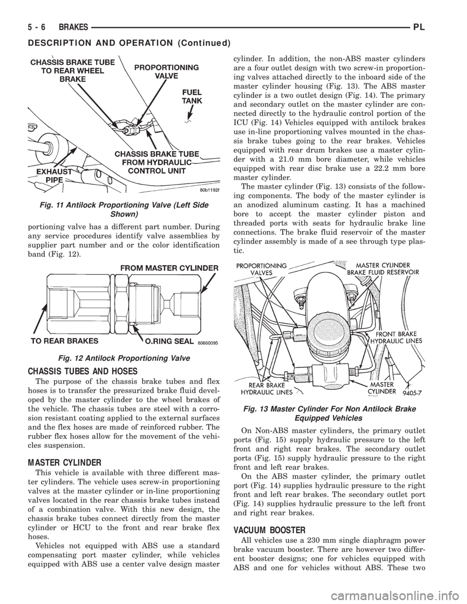
portioning valve has a different part number. During
any service procedures identify valve assemblies by
supplier part number and or the color identification
band (Fig. 12).
CHASSIS TUBES AND HOSES
The purpose of the chassis brake tubes and flex
hoses is to transfer the pressurized brake fluid devel-
oped by the master cylinder to the wheel brakes of
the vehicle. The chassis tubes are steel with a corro-
sion resistant coating applied to the external surfaces
and the flex hoses are made of reinforced rubber. The
rubber flex hoses allow for the movement of the vehi-
cles suspension.
MASTER CYLINDER
This vehicle is available with three different mas-
ter cylinders. The vehicle uses screw-in proportioning
valves at the master cylinder or in-line proportioning
valves located in the rear chassis brake tubes instead
of a combination valve. With this new design, the
chassis brake tubes connect directly from the master
cylinder or HCU to the front and rear brake flex
hoses.
Vehicles not equipped with ABS use a standard
compensating port master cylinder, while vehicles
equipped with ABS use a center valve design mastercylinder. In addition, the non-ABS master cylinders
are a four outlet design with two screw-in proportion-
ing valves attached directly to the inboard side of the
master cylinder housing (Fig. 13). The ABS master
cylinder is a two outlet design (Fig. 14). The primary
and secondary outlet on the master cylinder are con-
nected directly to the hydraulic control portion of the
ICU (Fig. 14) Vehicles equipped with antilock brakes
use in-line proportioning valves mounted in the chas-
sis brake tubes going to the rear brakes. Vehicles
equipped with rear drum brakes use a master cylin-
der with a 21.0 mm bore diameter, while vehicles
equipped with rear disc brake use a 22.2 mm bore
master cylinder.
The master cylinder (Fig. 13) consists of the follow-
ing components. The body of the master cylinder is
an anodized aluminum casting. It has a machined
bore to accept the master cylinder piston and
threaded ports with seats for hydraulic brake line
connections. The brake fluid reservoir of the master
cylinder assembly is made of a see through type plas-
tic.
On Non-ABS master cylinders, the primary outlet
ports (Fig. 15) supply hydraulic pressure to the left
front and right rear brakes. The secondary outlet
ports (Fig. 15) supply hydraulic pressure to the right
front and left rear brakes.
On the ABS master cylinder, the primary outlet
port (Fig. 14) supplies hydraulic pressure to the right
front and left rear brakes. The secondary outlet port
(Fig. 14) supplies hydraulic pressure to the left front
and right rear brakes.
VACUUM BOOSTER
All vehicles use a 230 mm single diaphragm power
brake vacuum booster. There are however two differ-
ent booster designs; one for vehicles equipped with
ABS and one for vehicles without ABS. These two
Fig. 11 Antilock Proportioning Valve (Left Side
Shown)
Fig. 12 Antilock Proportioning Valve
Fig. 13 Master Cylinder For Non Antilock Brake
Equipped Vehicles
5 - 6 BRAKESPL
DESCRIPTION AND OPERATION (Continued)
Page 96 of 1200
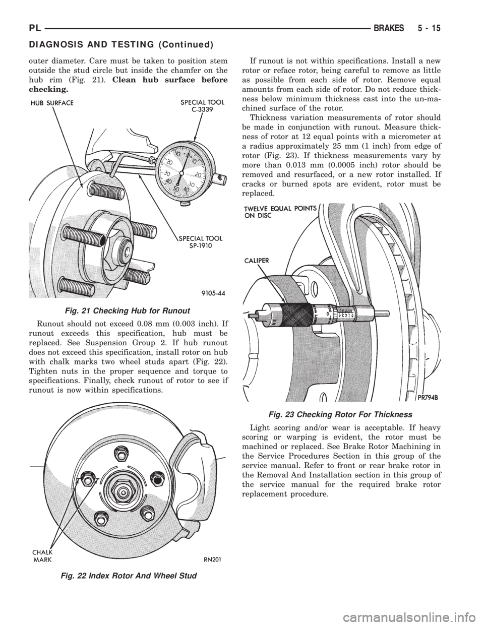
outer diameter. Care must be taken to position stem
outside the stud circle but inside the chamfer on the
hub rim (Fig. 21).Clean hub surface before
checking.
Runout should not exceed 0.08 mm (0.003 inch). If
runout exceeds this specification, hub must be
replaced. See Suspension Group 2. If hub runout
does not exceed this specification, install rotor on hub
with chalk marks two wheel studs apart (Fig. 22).
Tighten nuts in the proper sequence and torque to
specifications. Finally, check runout of rotor to see if
runout is now within specifications.If runout is not within specifications. Install a new
rotor or reface rotor, being careful to remove as little
as possible from each side of rotor. Remove equal
amounts from each side of rotor. Do not reduce thick-
ness below minimum thickness cast into the un-ma-
chined surface of the rotor.
Thickness variation measurements of rotor should
be made in conjunction with runout. Measure thick-
ness of rotor at 12 equal points with a micrometer at
a radius approximately 25 mm (1 inch) from edge of
rotor (Fig. 23). If thickness measurements vary by
more than 0.013 mm (0.0005 inch) rotor should be
removed and resurfaced, or a new rotor installed. If
cracks or burned spots are evident, rotor must be
replaced.
Light scoring and/or wear is acceptable. If heavy
scoring or warping is evident, the rotor must be
machined or replaced. See Brake Rotor Machining in
the Service Procedures Section in this group of the
service manual. Refer to front or rear brake rotor in
the Removal And Installation section in this group of
the service manual for the required brake rotor
replacement procedure.
Fig. 21 Checking Hub for Runout
Fig. 22 Index Rotor And Wheel Stud
Fig. 23 Checking Rotor For Thickness
PLBRAKES 5 - 15
DIAGNOSIS AND TESTING (Continued)
Page 119 of 1200
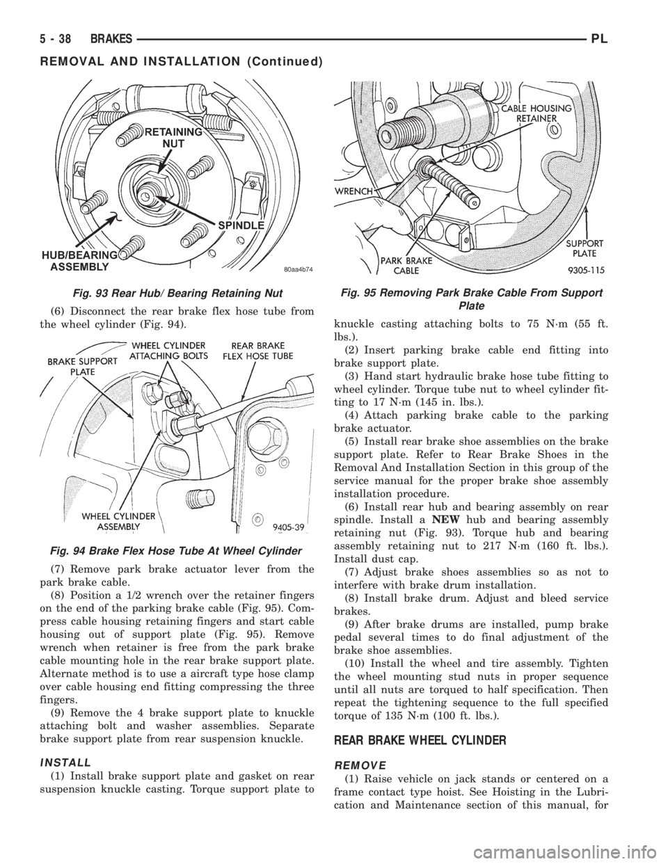
(6) Disconnect the rear brake flex hose tube from
the wheel cylinder (Fig. 94).
(7) Remove park brake actuator lever from the
park brake cable.
(8) Position a 1/2 wrench over the retainer fingers
on the end of the parking brake cable (Fig. 95). Com-
press cable housing retaining fingers and start cable
housing out of support plate (Fig. 95). Remove
wrench when retainer is free from the park brake
cable mounting hole in the rear brake support plate.
Alternate method is to use a aircraft type hose clamp
over cable housing end fitting compressing the three
fingers.
(9) Remove the 4 brake support plate to knuckle
attaching bolt and washer assemblies. Separate
brake support plate from rear suspension knuckle.
INSTALL
(1) Install brake support plate and gasket on rear
suspension knuckle casting. Torque support plate toknuckle casting attaching bolts to 75 N´m (55 ft.
lbs.).
(2) Insert parking brake cable end fitting into
brake support plate.
(3) Hand start hydraulic brake hose tube fitting to
wheel cylinder. Torque tube nut to wheel cylinder fit-
ting to 17 N´m (145 in. lbs.).
(4) Attach parking brake cable to the parking
brake actuator.
(5) Install rear brake shoe assemblies on the brake
support plate. Refer to Rear Brake Shoes in the
Removal And Installation Section in this group of the
service manual for the proper brake shoe assembly
installation procedure.
(6) Install rear hub and bearing assembly on rear
spindle. Install aNEWhub and bearing assembly
retaining nut (Fig. 93). Torque hub and bearing
assembly retaining nut to 217 N´m (160 ft. lbs.).
Install dust cap.
(7) Adjust brake shoes assemblies so as not to
interfere with brake drum installation.
(8) Install brake drum. Adjust and bleed service
brakes.
(9) After brake drums are installed, pump brake
pedal several times to do final adjustment of the
brake shoe assemblies.
(10) Install the wheel and tire assembly. Tighten
the wheel mounting stud nuts in proper sequence
until all nuts are torqued to half specification. Then
repeat the tightening sequence to the full specified
torque of 135 N´m (100 ft. lbs.).
REAR BRAKE WHEEL CYLINDER
REMOVE
(1) Raise vehicle on jack stands or centered on a
frame contact type hoist. See Hoisting in the Lubri-
cation and Maintenance section of this manual, for
Fig. 93 Rear Hub/ Bearing Retaining Nut
Fig. 94 Brake Flex Hose Tube At Wheel Cylinder
Fig. 95 Removing Park Brake Cable From Support
Plate
5 - 38 BRAKESPL
REMOVAL AND INSTALLATION (Continued)