1999 DODGE NEON suspension
[x] Cancel search: suspensionPage 151 of 1200
This is accomplished by a sophisticated system of
electrical and hydraulic components. As a result,
there are a few performance characteristics that may
at first seem different but should be considered nor-
mal. These characteristics are discussed below.
NORMAL BRAKING SYSTEM FUNCTION
Under normal braking conditions, the ABS System
functions the same as a standard brake system with
a diagonally split master cylinder and conventional
vacuum assist.
ABS SYSTEM OPERATION
If a wheel locking tendency is detected during a
brake application, the brake system will enter the
ABS mode. During ABS braking, hydraulic pressure
in the four wheel circuits is modulated to prevent
any wheel from locking. Each wheel circuit is
designed with a set of electric solenoids to allow mod-
ulation, although for vehicle stability, both rear
wheel solenoids receive the same electrical signal.
During an ABS stop, the brakes hydraulic system
is still diagonally split. However, the brake system
pressure is further split into four control channels.
During antilock operation of the vehicle's brake sys-
tem the front wheels are controlled independently
and are on two separate control channels and the
rear wheels of the vehicle are controlled together.
The system can build and release pressure at each
wheel, depending on signals generated by the wheel
speed sensors (WSS) at each wheel and received at
the Controller Antilock Brake (CAB).
ABS operation is available at all vehicle speeds
above 3 to 5 mph. Wheel lockup may be perceived at
the very end of an ABS stop and is considered nor-
mal.
VEHICLE HANDLING PERFORMANCE DURING
ABS BRAKING
It is important to remember that an antilock brake
system does not shorten a vehicle's stopping distance
under all driving conditions, but does provide
improved control of the vehicle while stopping. Vehi-
cle stopping distance is still dependent on vehicle
speed, weight, tires, road surfaces and other factors.
Though ABS provides the driver with some steer-
ing control during hard braking, there are conditions
however, where the system does not provide any ben-
efit. In particular, hydroplaning is still possible when
the tires ride on a film of water. This results in the
vehicles tires leaving the road surface rendering the
vehicle virtually uncontrollable. In addition, extreme
steering maneuvers at high speed or high speed cor-
nering beyond the limits of tire adhesion to the road
surface may cause vehicle skidding, independent of
vehicle braking. For this reason, the ABS system is
termed Antilock instead of Anti-Skid.
NOISE AND BRAKE PEDAL FEEL
During ABS braking, some brake pedal movement
may be felt. In addition, ABS braking will create
ticking, popping and/or groaning noises heard by the
driver. This is normal due to pressurized fluid being
transferred between the master cylinder and the
brakes. If ABS operation occurs during hard braking,
some pulsation may be felt in the vehicle body due to
fore and aft movement of the suspension as brake
pressures are modulated.
At the end of an ABS stop, ABS will be turned off
when the vehicle is slowed to a speed of 3±4 mph.
There may be a slight brake pedal drop anytime that
the ABS is deactivated, such as at the end of the stop
when the vehicle speed is less then 3 mph or during
an ABS stop where ABS is no longer required. These
conditions will exist when a vehicle is being stopped
on a road surface with patches of ice, loose gravel or
sand on it. Also stopping a vehicle on a bumpy road
surface will activate ABS because of the wheel hop
caused by the bumps.
TIRE NOISE AND MARKS
Although the ABS system prevents complete wheel
lock-up, some wheel slip is desired in order to
achieve optimum braking performance. Wheel slip is
defined as follows, 0 percent slip means the wheel is
rolling freely and 100 percent slip means the wheel is
fully locked. During brake pressure modulation,
wheel slip is allowed to reach up to 25 to30%. This
means that the wheel rolling velocity is 25 to 30%
less than that of a free rolling wheel at a given vehi-
cle speed. This slip may result in some tire chirping,
depending on the road surface. This sound should not
be interpreted as total wheel lock-up.
Complete wheel lock up normally leaves black tire
marks on dry pavement. The ABS System will not
leave dark black tire marks since the wheel never
reaches a fully locked condition. Tire marks may
however be noticeable as light patched marks.
START UP CYCLE
When the ignition is turned on, a popping sound
and a slight brake pedal movement may be noticed.
Additionally, when the vehicle is first driven off a
humming may be heard and/or felt by the driver at
approximately 20 to 40 kph (12 to 25 mph). The ABS
warning lamp will also be on for up to 5 seconds
after the ignition is turned on. All of these conditions
are a normal function of ABS as the system is per-
forming a diagnosis check.
5 - 70 BRAKESPL
DESCRIPTION AND OPERATION (Continued)
Page 174 of 1200
CLUTCH PEDAL POSITION
SWITCH±MECHANICAL TEST
With the park brake set and the vehicleIN NEU-
TRAL,turn the key to the start position. The vehicle
should not crank. If the vehicle cranks, the switch is
defective (shorted out) and must be replaced. If the
vehicle does not crank, proceed to the next step.
WARNING: BEFORE PERFORMING THIS STEP, BE
SURE THAT THE AREA IN FRONT OF THE VEHICLE
IS CLEAR OF OBSTRUCTIONS AND PEOPLE. VEHI-
CLE MAY MOVE WHEN PERFORMING THIS TEST.
With the park brake set and the vehicleIN GEAR,
turn the key to the start position and hold it there.
Slowly depress the clutch pedal and feel for any
vehicle motion when the starter is energized. If there
is no motion, the switch is working properly.
If motion is felt, check to see if the switch is mak-
ing contact when the pedal is between 25 mm (1.0
in.) and 6 mm (0.25 in.) from the floor. If this condi-
tion is met, then the problem is either the clutch orthe self-adjusting cable (See ªClutch Will Not Disen-
gage Properlyº). If this condition is not met, then the
switch mounting tab on the brake bracket is bent,
and the brake bracket must be replaced.
If vehicle will not crank, even with clutch pedal
pressed to the floor, refer to ªService Diagnosis-
Clutch Pedal Position Switchº chart in this section.
CLUTCH DIAGNOSIS
Problem diagnosis will generally require a road
test to determine the type of fault. Component
inspection will then determine the problem after road
testing.
Drive the vehicle at normal speeds during road
test. Shift the transaxle through all gear ranges and
observe clutch action. If chatter, grab, slip, or
improper release is experienced, remove and inspect
the clutch components. If the problem is noise or
hard shifting, further diagnosis may be needed. The
transaxle or other driveline components may actually
be at fault.
SERVICE DIAGNOSISÐCLUTCH GRAB/CHATTER
CONDITION POSSIBLE CAUSES CORRECTION
CLUTCH DISC FACING
COVERED WITH OIL OR
GREASEOil leak at engine rear main or
transaxle input shaft sealCorrect leak and replace w/modular clutch
assembly
Too much grease applied to splines
of disc and input shaftApply lighter coating of grease to splines
NO FAULT FOUND WITH
CLUTCH
COMPONENTSProblem actually related to
suspension or driveline componentFurther diagnosis required. Check
engine/transmission mounts, suspension
attaching parts and other driveline
components as needed.
Engine related problems Check EFI and ignition systems
PARTIAL ENGAGEMENT
OF CLUTCH DISCClutch cover, spring, or release
fingers bent, distorted (rough
handling, improper assembly)Replace w/modular clutch assembly
Clutch disc damaged or distorted Replace w/modular clutch assembly
Clutch misalignment Check alignment and runout of flywheel,
disc, or cover. Check clutch housing to
engine dowels and dowel holes for damage.
Correct as necessary.
PLCLUTCH 6 - 3
DIAGNOSIS AND TESTING (Continued)
Page 186 of 1200
SERVICE DIAGNOSISÐCLUTCH GRAB/CHATTER
CONDITION POSSIBLE CAUSES CORRECTION
CLUTCH DISC FACING
COVERED WITH OIL OR
GREASEOil leak at engine rear main or
transaxle input shaft sealCorrect leak and replace w/modular
clutch assembly
Too much grease applied to splines
of disc and input shaftApply lighter coating of grease to
splines
NO FAULT FOUND WITH
CLUTCH
COMPONENTSProblem actually related to
suspension or driveline componentFurther diagnosis required. Check
engine/transmission mounts,
suspension attaching parts and other
driveline components as needed.
Engine related problems Check EFI and ignition systems
PARTIAL ENGAGEMENT OF
CLUTCH DISCClutch cover, spring, or release
fingers bent, distorted (rough
handling, improper assembly)Replace w/modular clutch assembly
Clutch disc damaged or distorted Replace w/modular clutch assembly
Clutch misalignment Check alignment and runout of
flywheel, disc, or cover. Check clutch
housing to engine dowels and dowel
holes for damage. Correct as
necessary.
PLCLUTCH 6 - 3
DIAGNOSIS AND TESTING (Continued)
Page 333 of 1200
HEADLAMP ALIGNMENT
INDEX
page page
GENERAL INFORMATION
HEADLAMP ALIGNMENT................... 4
SERVICE PROCEDURES
HEADLAMP ALIGNMENT PREPARATION....... 4ADJUSTMENTS
FOG LAMP ALIGNMENT................... 4
HEADLAMP ADJUSTMENT USING ALIGNMENT
SCREEN.............................. 4
GENERAL INFORMATION
HEADLAMP ALIGNMENT
Headlamps can be aligned using the screen method
provided in this section.
SERVICE PROCEDURES
HEADLAMP ALIGNMENT PREPARATION
(1) Verify headlamp dimmer switch and high beam
indicator operation.
(2) Inspect and correct damaged or defective com-
ponents that could interfere with proper headlamp
alignment.
(3) Verify proper tire inflation.
(4) Clean headlamp lenses.
(5) Verify that luggage area is not heavily loaded.
(6) Fuel tank should be FULL. Add 2.94 kg (6.5
lbs.) of weight over the fuel tank for each estimated
gallon of missing fuel.
ADJUSTMENTS
HEADLAMP ADJUSTMENT USING ALIGNMENT
SCREEN
ALIGNMENT SCREEN PREPARATION
(1) Position vehicle on a level surface perpendicu-
lar to a flat wall 7.62 meters (25 ft.) away from front
of headlamp lens (Fig. 1).
(2) If necessary, tape a line on the floor 7.62
meters (25 ft.) away from and parallel to the wall.
(3) From the floor up 1.27 meters (5 ft.), tape a
line on the wall at the center line of the vehicle.
Sight along the center line of the vehicle (from rear
of vehicle forward) to verify accuracy of the line
placement.
(4) Rock vehicle side-to-side three times to allow
suspension to stabilize.(5) Jounce front suspension three times by pushing
downward on front bumper and releasing.
(6) Measure the distance from the center of head-
lamp lens to the floor. Transfer measurement to the
alignment screen (with tape). Use this line for
up/down adjustment reference.
(7) Measure distance from the center line of the
vehicle to the center of each headlamp being aligned.
Transfer measurements to screen (with tape) to each
side of vehicle center line. Use these lines for left/
right adjustment reference.
HEADLAMP ADJUSTMENT
A properly aimed low beam headlamp will project
the center of the low beam hot spot on the alignment
screen from 178 mm (7 in.) below the headlamp cen-
ter line. The side- to-side left edge of low beam hot
spot should be 127 mm (5 in.) to the right of head-
lamp center line (Fig. 1). The high beams on a vehi-
cle with aero headlamps cannot be aligned. The high
beam pattern should be correct when the low beams
are aligned properly.
To adjust headlamp alignment, rotate alignment
screws to achieve the specified low beam hot spot
pattern.
FOG LAMP ALIGNMENT
Prepare an alignment screen. Refer to Alignment
Screen Preparation paragraph in this section. Disen-
gage the wire connectors from the back of the head-
lamp bulbs to disable the headlamps. This will allow
a more accurate projection reading of the fog lamps.
Turn on the headlamp switch and actuate the fog
lamp switch. A properly aligned fog lamp will project
a pattern on the alignment screen 100 mm (4 in.)
below the fog lamp centerline and straight ahead
(Fig. 2).
8L - 4 LAMPSPL
Page 397 of 1200
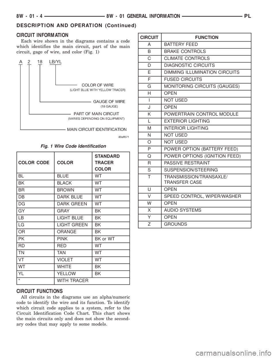
CIRCUIT INFORMATION
Each wire shown in the diagrams contains a code
which identifies the main circuit, part of the main
circuit, gage of wire, and color (Fig. 1)
CIRCUIT FUNCTIONS
All circuits in the diagrams use an alpha/numeric
code to identify the wire and its function. To identify
which circuit code applies to a system, refer to the
Circuit Identification Code Chart. This chart shows
the main circuits only and does not show the second-
ary codes that may apply to some models.
Fig. 1 Wire Code Identification
COLOR CODE COLORSTANDARD
TRACER
COLOR
BL BLUE WT
BK BLACK WT
BR BROWN WT
DB DARK BLUE WT
DG DARK GREEN WT
GY GRAY BK
LB LIGHT BLUE BK
LG LIGHT GREEN BK
OR ORANGE BK
PK PINK BK or WT
RD RED WT
TN TAN WT
VT VIOLET WT
WT WHITE BK
YL YELLOW BK
* WITH TRACER
CIRCUIT FUNCTION
A BATTERY FEED
B BRAKE CONTROLS
C CLIMATE CONTROLS
D DIAGNOSTIC CIRCUITS
E DIMMING ILLUMINATION CIRCUITS
F FUSED CIRCUITS
G MONITORING CIRCUITS (GAUGES)
H OPEN
I NOT USED
J OPEN
K POWERTRAIN CONTROL MODULE
L EXTERIOR LIGHTING
M INTERIOR LIGHTING
N NOT USED
O NOT USED
P POWER OPTION (BATTERY FEED)
Q POWER OPTIONS (IGNITION FEED)
R PASSIVE RESTRAINT
S SUSPENSION/STEERING
T TRANSMISSION/TRANSAXLE/
TRANSFER CASE
U OPEN
V SPEED CONTROL, WIPER/WASHER
W OPEN
X AUDIO SYSTEMS
Y OPEN
Z GROUNDS
8W - 01 - 4 8W - 01 GENERAL INFORMATIONPL
DESCRIPTION AND OPERATION (Continued)
Page 731 of 1200
REMOVAL AND INSTALLATION
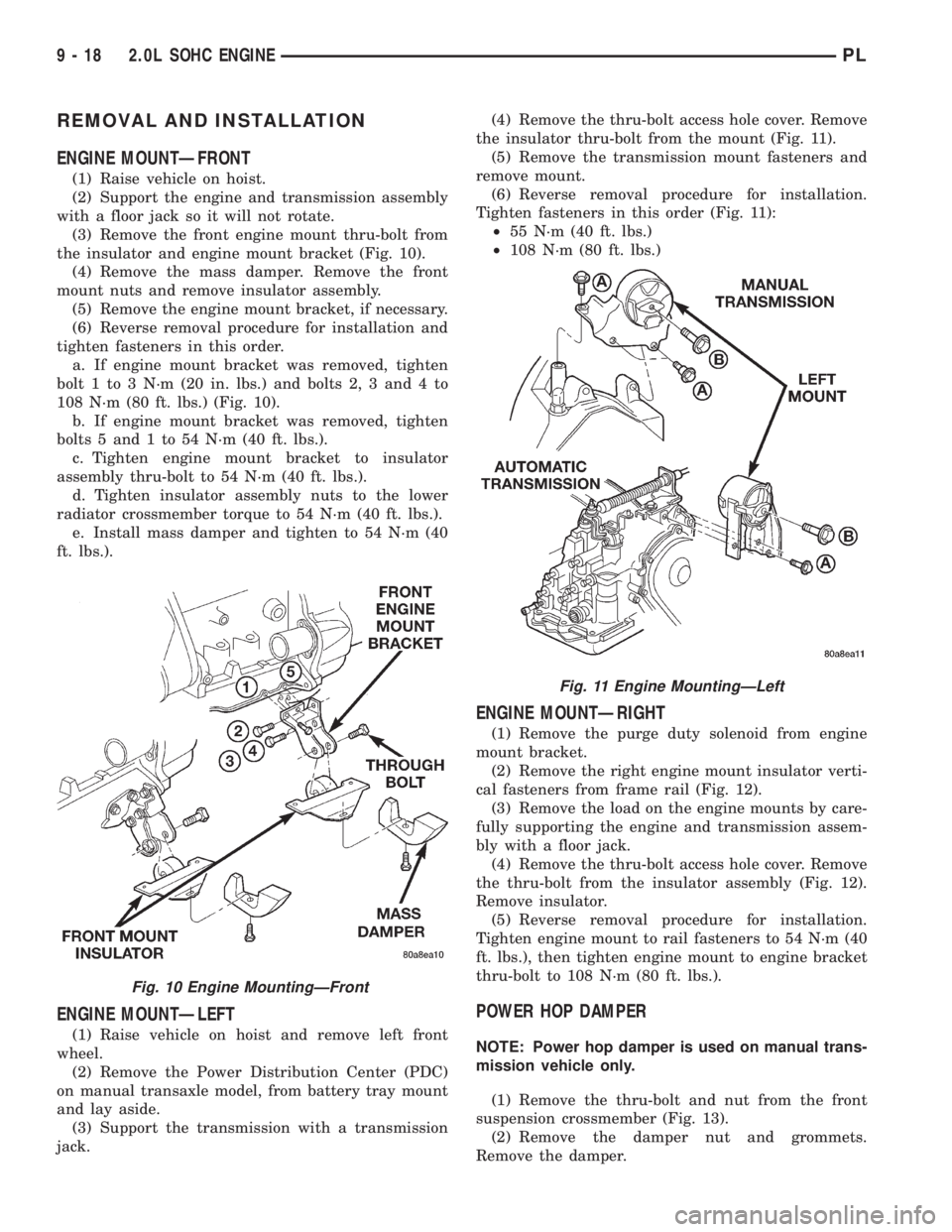
ENGINE MOUNTÐFRONT
(1) Raise vehicle on hoist.
(2) Support the engine and transmission assembly
with a floor jack so it will not rotate.
(3) Remove the front engine mount thru-bolt from
the insulator and engine mount bracket (Fig. 10).
(4) Remove the mass damper. Remove the front
mount nuts and remove insulator assembly.
(5) Remove the engine mount bracket, if necessary.
(6) Reverse removal procedure for installation and
tighten fasteners in this order.
a. If engine mount bracket was removed, tighten
bolt 1 to 3 N´m (20 in. lbs.) and bolts 2, 3 and 4 to
108 N´m (80 ft. lbs.) (Fig. 10).
b. If engine mount bracket was removed, tighten
bolts 5 and 1 to 54 N´m (40 ft. lbs.).
c. Tighten engine mount bracket to insulator
assembly thru-bolt to 54 N´m (40 ft. lbs.).
d. Tighten insulator assembly nuts to the lower
radiator crossmember torque to 54 N´m (40 ft. lbs.).
e. Install mass damper and tighten to 54 N´m (40
ft. lbs.).
ENGINE MOUNTÐLEFT
(1) Raise vehicle on hoist and remove left front
wheel.
(2) Remove the Power Distribution Center (PDC)
on manual transaxle model, from battery tray mount
and lay aside.
(3) Support the transmission with a transmission
jack.(4) Remove the thru-bolt access hole cover. Remove
the insulator thru-bolt from the mount (Fig. 11).
(5) Remove the transmission mount fasteners and
remove mount.
(6) Reverse removal procedure for installation.
Tighten fasteners in this order (Fig. 11):
²55 N´m (40 ft. lbs.)
²108 N´m (80 ft. lbs.)
ENGINE MOUNTÐRIGHT
(1) Remove the purge duty solenoid from engine
mount bracket.
(2) Remove the right engine mount insulator verti-
cal fasteners from frame rail (Fig. 12).
(3) Remove the load on the engine mounts by care-
fully supporting the engine and transmission assem-
bly with a floor jack.
(4) Remove the thru-bolt access hole cover. Remove
the thru-bolt from the insulator assembly (Fig. 12).
Remove insulator.
(5) Reverse removal procedure for installation.
Tighten engine mount to rail fasteners to 54 N´m (40
ft. lbs.), then tighten engine mount to engine bracket
thru-bolt to 108 N´m (80 ft. lbs.).
POWER HOP DAMPER
NOTE: Power hop damper is used on manual trans-
mission vehicle only.
(1) Remove the thru-bolt and nut from the front
suspension crossmember (Fig. 13).
(2) Remove the damper nut and grommets.
Remove the damper.
Fig. 10 Engine MountingÐFront
Fig. 11 Engine MountingÐLeft
9 - 18 2.0L SOHC ENGINEPL
Page 777 of 1200
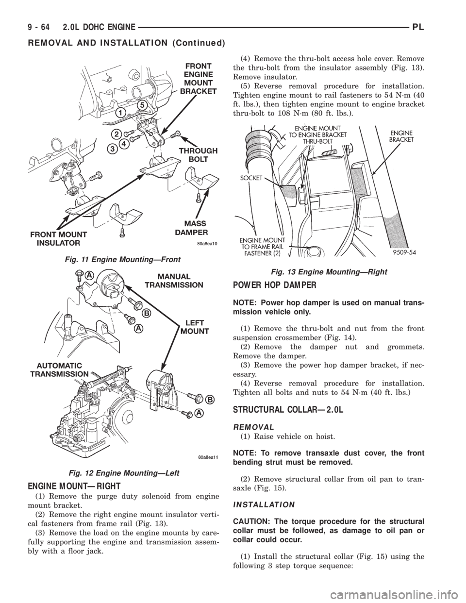
ENGINE MOUNTÐRIGHT
(1) Remove the purge duty solenoid from engine
mount bracket.
(2) Remove the right engine mount insulator verti-
cal fasteners from frame rail (Fig. 13).
(3) Remove the load on the engine mounts by care-
fully supporting the engine and transmission assem-
bly with a floor jack.(4) Remove the thru-bolt access hole cover. Remove
the thru-bolt from the insulator assembly (Fig. 13).
Remove insulator.
(5) Reverse removal procedure for installation.
Tighten engine mount to rail fasteners to 54 N´m (40
ft. lbs.), then tighten engine mount to engine bracket
thru-bolt to 108 N´m (80 ft. lbs.).
POWER HOP DAMPER
NOTE: Power hop damper is used on manual trans-
mission vehicle only.
(1) Remove the thru-bolt and nut from the front
suspension crossmember (Fig. 14).
(2) Remove the damper nut and grommets.
Remove the damper.
(3) Remove the power hop damper bracket, if nec-
essary.
(4) Reverse removal procedure for installation.
Tighten all bolts and nuts to 54 N´m (40 ft. lbs.)
STRUCTURAL COLLARÐ2.0L
REMOVAL
(1) Raise vehicle on hoist.
NOTE: To remove transaxle dust cover, the front
bending strut must be removed.
(2) Remove structural collar from oil pan to tran-
saxle (Fig. 15).
INSTALLATION
CAUTION: The torque procedure for the structural
collar must be followed, as damage to oil pan or
collar could occur.
(1) Install the structural collar (Fig. 15) using the
following 3 step torque sequence:
Fig. 11 Engine MountingÐFront
Fig. 12 Engine MountingÐLeft
Fig. 13 Engine MountingÐRight
9 - 64 2.0L DOHC ENGINEPL
REMOVAL AND INSTALLATION (Continued)
Page 820 of 1200
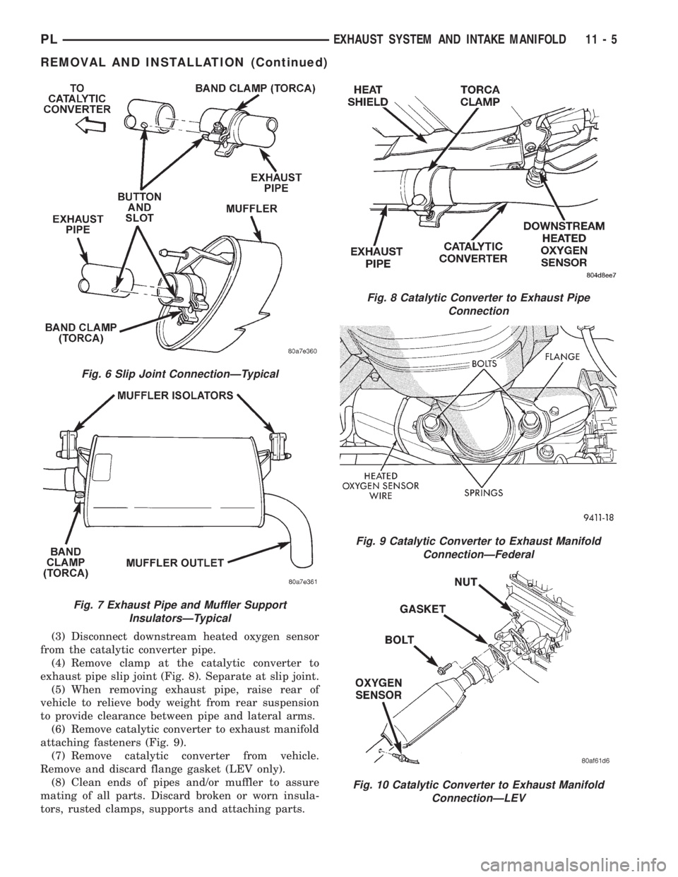
(3) Disconnect downstream heated oxygen sensor
from the catalytic converter pipe.
(4) Remove clamp at the catalytic converter to
exhaust pipe slip joint (Fig. 8). Separate at slip joint.
(5) When removing exhaust pipe, raise rear of
vehicle to relieve body weight from rear suspension
to provide clearance between pipe and lateral arms.
(6) Remove catalytic converter to exhaust manifold
attaching fasteners (Fig. 9).
(7) Remove catalytic converter from vehicle.
Remove and discard flange gasket (LEV only).
(8) Clean ends of pipes and/or muffler to assure
mating of all parts. Discard broken or worn insula-
tors, rusted clamps, supports and attaching parts.
Fig. 6 Slip Joint ConnectionÐTypical
Fig. 7 Exhaust Pipe and Muffler Support
InsulatorsÐTypical
Fig. 8 Catalytic Converter to Exhaust Pipe
Connection
Fig. 9 Catalytic Converter to Exhaust Manifold
ConnectionÐFederal
Fig. 10 Catalytic Converter to Exhaust Manifold
ConnectionÐLEV
PLEXHAUST SYSTEM AND INTAKE MANIFOLD 11 - 5
REMOVAL AND INSTALLATION (Continued)