1998 OPEL FRONTERA rack
[x] Cancel search: rackPage 5316 of 6000
ENGINE MECHANICAL 6A – 43
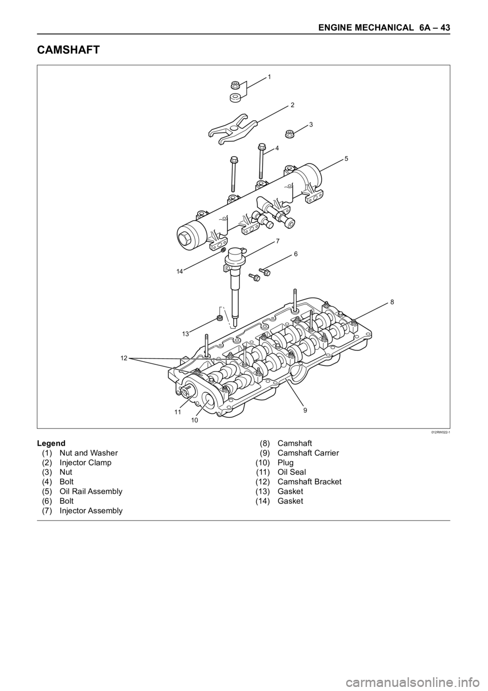
CAMSHAFT
2 1
6
13 14
8
12
11
109
3
4
7
5
012RW022-1
Legend
(1) Nut and Washer
(2) Injector Clamp
(3) Nut
(4) Bolt
(5) Oil Rail Assembly
(6) Bolt
(7) Injector Assembly(8) Camshaft
(9) Camshaft Carrier
(10) Plug
(11) Oil Seal
(12) Camshaft Bracket
(13) Gasket
(14) Gasket
Page 5317 of 6000
6A – 44 ENGINE MECHANICAL
DISASSEMBLY
1. Injector clamp and spacer.
2. Injector assembly
3. Oil rail assembly
4. Camshaft bracket
5. Camshaft
6. Oil seal
7. Plug
NOTE: Before starting disassembly above, drain oil
from oil rail to prevent oil from entering the cylinder.
REASSEMBLY
1. Camshaft
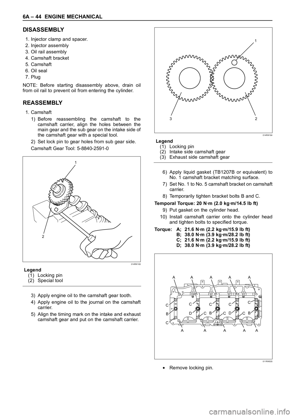
1) Before reassembling the camshaft to the
camshaft carrier, align the holes between the
main gear and the sub gear on the intake side of
the camshaft gear with a special tool.
2) Set lock pin to gear holes from sub gear side.
Camshaft Gear Tool: 5-8840-2591-0
Legend
(1) Locking pin
(2) Special tool
3) Apply engine oil to the camshaft gear tooth.
4) Apply engine oil to the journal on the camshaft
carrier.
5) Align the timing mark on the intake and exhaust
camshaft gear and put on the camshaft carrier.Legend
(1) Locking pin
(2) Intake side camshaft gear
(3) Exhaust side camshaft gear
6) Apply liquid gasket (TB1207B or equivalent) to
No. 1 camshaft bracket matching surface.
7) Set No. 1 to No. 5 camshaft bracket on camshaft
carrier.
8) Temporarily tighten bracket bolts B and C.
Temporal Torque: 20 Nꞏm (2.0 kgꞏm/14.5 lb ft)
9) Put gasket on the cylinder head.
10) Install camshaft carrier onto the cylinder head
and tighten bolts to specified torque.
Torque: A; 21.6 Nꞏm (2.2 kgꞏm/15.9 lb ft)
B; 38.0 Nꞏm (3.9 kgꞏm/28.2 lb ft)
C; 21.6 Nꞏm (2.2 kgꞏm/15.9 lb ft)
D; 38.0 Nꞏm (3.9 kgꞏm/28.2 lb ft)
Remove locking pin.
1
2
014RW183
321
014RW184
CC
D
B
CC
B
CC
D
CC
B
C
A AA A A A
AAAA
011RW035
Page 5318 of 6000
ENGINE MECHANICAL 6A – 45
INSPECTION AND REPAIR
Make the necessary adjustments, repairs, and part
replacements if excessive wear or damage is
discovered during inspection.
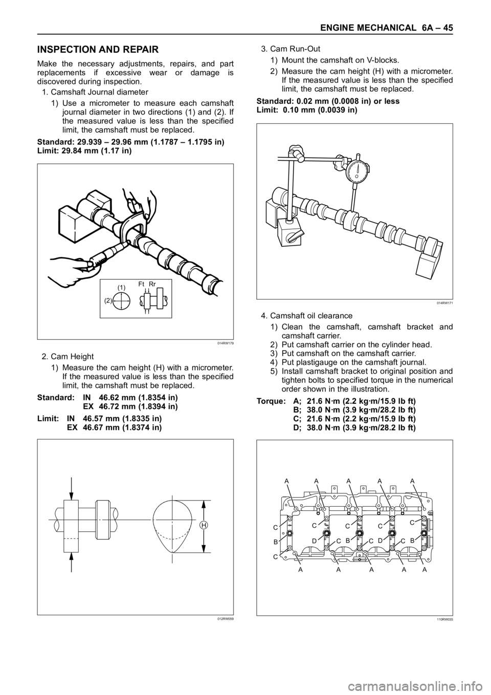
1. Camshaft Journal diameter
1) Use a micrometer to measure each camshaft
journal diameter in two directions (1) and (2). If
the measured value is less than the specified
limit, the camshaft must be replaced.
Standard: 29.939 – 29.96 mm (1.1787 – 1.1795 in)
Limit: 29.84 mm (1.17 in)
2. Cam Height
1) Measure the cam height (H) with a micrometer.
If the measured value is less than the specified
limit, the camshaft must be replaced.
Standard: IN 46.62 mm (1.8354 in)
EX 46.72 mm (1.8394 in)
Limit: IN 46.57 mm (1.8335 in)
EX 46.67 mm (1.8374 in)3. Cam Run-Out
1) Mount the camshaft on V-blocks.
2) Measure the cam height (H) with a micrometer.
If the measured value is less than the specified
limit, the camshaft must be replaced.
Standard: 0.02 mm (0.0008 in) or less
Limit: 0.10 mm (0.0039 in)
4. Camshaft oil clearance
1) Clean the camshaft, camshaft bracket and
camshaft carrier.
2) Put camshaft carrier on the cylinder head.
3) Put camshaft on the camshaft carrier.
4) Put plastigauge on the camshaft journal.
5) Install camshaft bracket to original position and
tighten bolts to specified torque in the numerical
order shown in the illustration.
Torque: A; 21.6 Nꞏm (2.2 kgꞏm/15.9 lb ft)
B; 38.0 Nꞏm (3.9 kgꞏm/28.2 lb ft)
C; 21.6 Nꞏm (2.2 kgꞏm/15.9 lb ft)
D; 38.0 Nꞏm (3.9 kgꞏm/28.2 lb ft)
(1)Ft Rr
(2)
014RW179
H
012RW059
014RW171
CC
D
B
CC
B
CC
D
CC
B
C
A AA A A A
AAAA
110RW035
Page 5319 of 6000
6A – 46 ENGINE MECHANICAL
NOTE: Do not allow the camshaft to rotate.
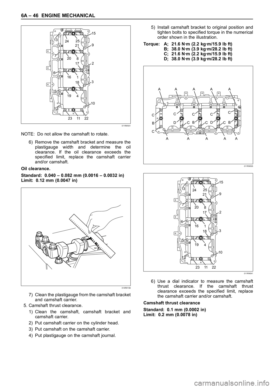
6) Remove the camshaft bracket and measure the
plastigauge width and determine the oil
clearance. If the oil clearance exceeds the
specified limit, replace the camshaft carrier
and/or camshaft.
Oil clearance.
Standard: 0.040 – 0.082 mm (0.0016 – 0.0032 in)
Limit: 0.12 mm (0.0047 in)
7) Clean the plastigauge from the camshaft bracket
and camshaft carrier.
5. Camshaft thrust clearance.
1) Clean the camshaft, camshaft bracket and
camshaft carrier.
2) Put camshaft carrier on the cylinder head.
3) Put camshaft on the camshaft carrier.
4) Put plastigauge on the camshaft journal.5) Install camshaft bracket to original position and
tighten bolts to specified torque in the numerical
order shown in the illustration.
Torque: A; 21.6 Nꞏm (2.2 kgꞏm/15.9 lb ft)
B; 38.0 Nꞏm (3.9 kgꞏm/28.2 lb ft)
C; 21.6 Nꞏm (2.2 kgꞏm/15.9 lb ft)
D; 38.0 Nꞏm (3.9 kgꞏm/28.2 lb ft)
6) Use a dial indicator to measure the camshaft
thrust clearance. If the camshaft thrust
clearance exceeds the specified limit, replace
the camshaft carrier and/or camshaft.
Camshaft thrust clearance
Standard: 0.1 mm (0.0002 in)
Limit: 0.2 mm (0.0078 in)
13
7
6
5
1215
2
3
10
9
20
8
19
2322
4
161
11 25
24
21
17
18
011RW041
014RW185
CC
D
B
CC
B
CC
D
CC
B
C
A AA A A A
AAAA
011RW035
13
7
6
5
1215
2
3
10
9
20
8
19
2322
4
161
11 25
24
21
17
18
011RW041
Page 5327 of 6000
6A – 54 ENGINE MECHANICAL
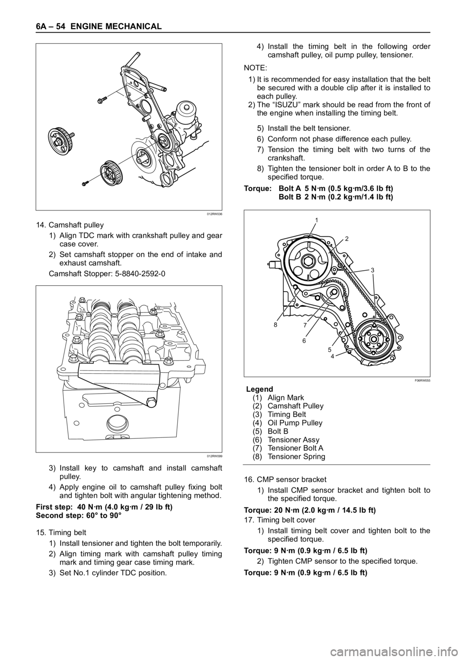
14. Camshaft pulley
1) Align TDC mark with crankshaft pulley and gear
case cover.
2) Set camshaft stopper on the end of intake and
exhaust camshaft.
Camshaft Stopper: 5-8840-2592-0
3) Install key to camshaft and install camshaft
pulley.
4) Apply engine oil to camshaft pulley fixing bolt
and tighten bolt with angular tightening method.
First step: 40 Nꞏm (4.0 kgꞏm / 29 lb ft)
Second step: 60° to 90°
15. Timing belt
1) Install tensioner and tighten the bolt temporarily.
2) Align timing mark with camshaft pulley timing
mark and timing gear case timing mark.
3) Set No.1 cylinder TDC position.4) Install the timing belt in the following order
camshaft pulley, oil pump pulley, tensioner.
NOTE:
1) It is recommended for easy installation that the belt
be secured with a double clip after it is installed to
each pulley.
2) The “ISUZU” mark should be read from the front of
the engine when installing the timing belt.
5) Install the belt tensioner.
6) Conform not phase difference each pulley.
7) Tension the timing belt with two turns of the
crankshaft.
8) Tighten the tensioner bolt in order A to B to the
specified torque.
Torque: Bolt A 5 Nꞏm (0.5 kgꞏm/3.6 lb ft)
Bolt B 2 Nꞏm (0.2 kgꞏm/1.4 lb ft)
Legend
(1) Align Mark
(2) Camshaft Pulley
(3) Timing Belt
(4) Oil Pump Pulley
(5) Bolt B
(6) Tensioner Assy
(7) Tensioner Bolt A
(8) Tensioner Spring
16. CMP sensor bracket
1) Install CMP sensor bracket and tighten bolt to
the specified torque.
Torque: 20 Nꞏm (2.0 kgꞏm / 14.5 lb ft)
17. Timing belt cover
1) Install timing belt cover and tighten bolt to the
specified torque.
Torque: 9 Nꞏm (0.9 kgꞏm / 6.5 lb ft)
2) Tighten CMP sensor to the specified torque.
Torque: 9 Nꞏm (0.9 kgꞏm / 6.5 lb ft)
012RW036
012RW099
1
2
3
8
67
4 5
F06RW055
Page 5329 of 6000
6A – 56 ENGINE MECHANICAL
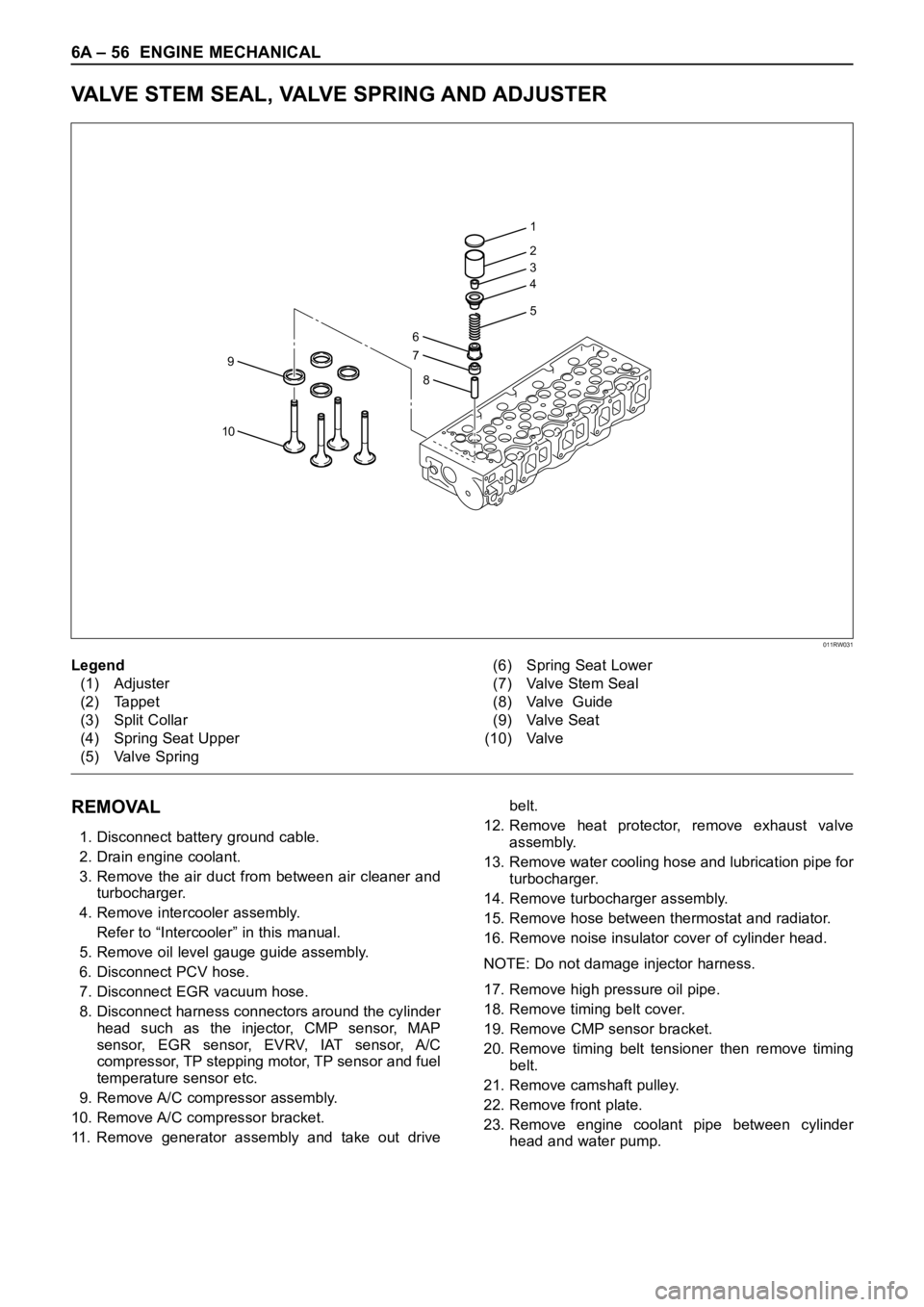
VALVE STEM SEAL, VALVE SPRING AND ADJUSTER
REMOVAL
1. Disconnect battery ground cable.
2. Drain engine coolant.
3. Remove the air duct from between air cleaner and
turbocharger.
4. Remove intercooler assembly.
Refer to “Intercooler” in this manual.
5. Remove oil level gauge guide assembly.
6. Disconnect PCV hose.
7. Disconnect EGR vacuum hose.
8. Disconnect harness connectors around the cylinder
head such as the injector, CMP sensor, MAP
sensor, EGR sensor, EVRV, IAT sensor, A/C
compressor, TP stepping motor, TP sensor and fuel
temperature sensor etc.
9. Remove A/C compressor assembly.
10. Remove A/C compressor bracket.
11. Remove generator assembly and take out drivebelt.
12. Remove heat protector, remove exhaust valve
assembly.
13. Remove water cooling hose and lubrication pipe for
turbocharger.
14. Remove turbocharger assembly.
15. Remove hose between thermostat and radiator.
16. Remove noise insulator cover of cylinder head.
NOTE: Do not damage injector harness.
17. Remove high pressure oil pipe.
18. Remove timing belt cover.
19. Remove CMP sensor bracket.
20. Remove timing belt tensioner then remove timing
belt.
21. Remove camshaft pulley.
22. Remove front plate.
23. Remove engine coolant pipe between cylinder
head and water pump.
1
2
3
4
5
6
9
10
7
8
011RW031
Legend
(1) Adjuster
(2) Tappet
(3) Split Collar
(4) Spring Seat Upper
(5) Valve Spring(6) Spring Seat Lower
(7) Valve Stem Seal
(8) Valve Guide
(9) Valve Seat
(10) Valve
Page 5335 of 6000
6A – 62 ENGINE MECHANICAL
INSTALLATION
1. Valve stem seal
1) Use the special tool to install the stem seal to the
valve guide.
Stem Seal Installer: 5-8840-2033-0
2. Valve spring.
1) Install the lower valve seat spring, valve spring,
then the upper valve spring seat.
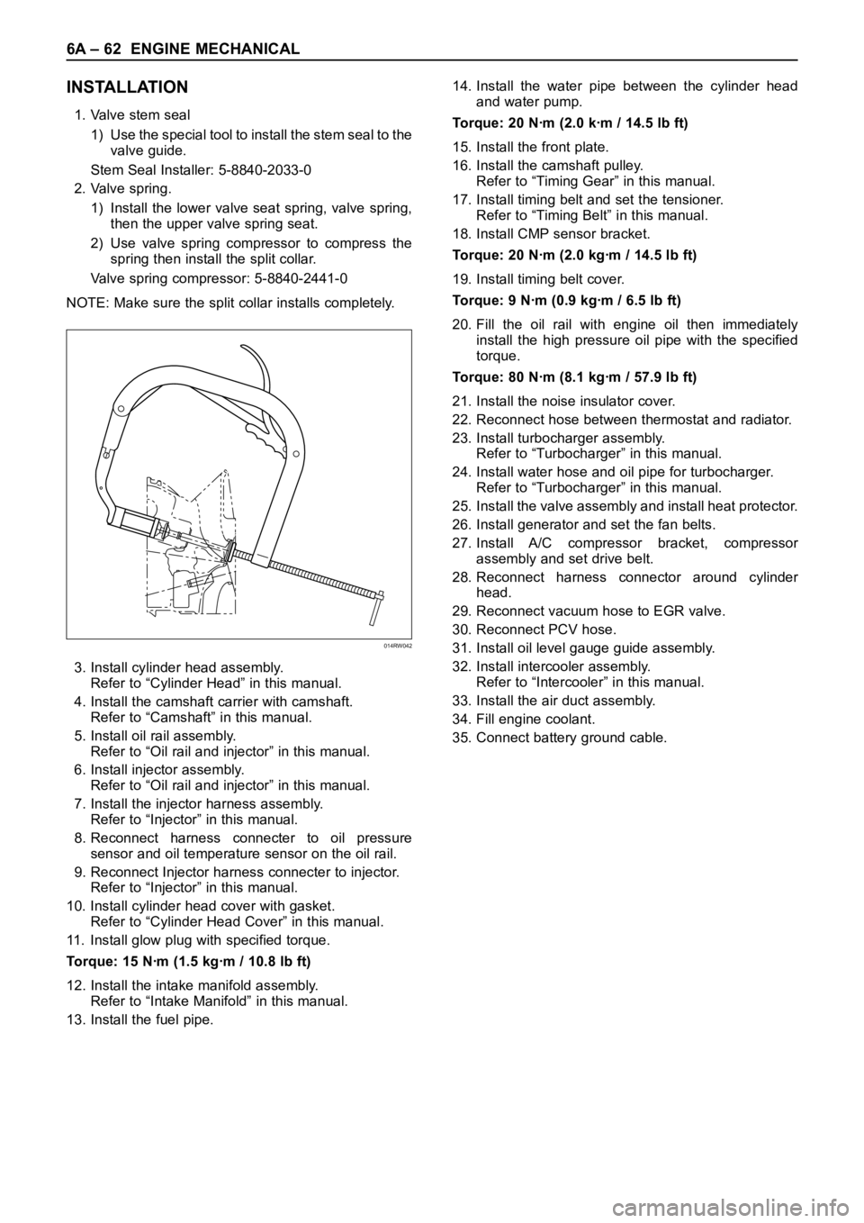
2) Use valve spring compressor to compress the
spring then install the split collar.
Valve spring compressor: 5-8840-2441-0
NOTE: Make sure the split collar installs completely.
3. Install cylinder head assembly.
Refer to “Cylinder Head” in this manual.
4. Install the camshaft carrier with camshaft.
Refer to “Camshaft” in this manual.
5. Install oil rail assembly.
Refer to “Oil rail and injector” in this manual.
6. Install injector assembly.
Refer to “Oil rail and injector” in this manual.
7. Install the injector harness assembly.
Refer to “Injector” in this manual.
8. Reconnect harness connecter to oil pressure
sensor and oil temperature sensor on the oil rail.
9. Reconnect Injector harness connecter to injector.
Refer to “Injector” in this manual.
10. Install cylinder head cover with gasket.
Refer to “Cylinder Head Cover” in this manual.
11. Install glow plug with specified torque.
Torque: 15 Nꞏm (1.5 kgꞏm / 10.8 lb ft)
12. Install the intake manifold assembly.
Refer to “Intake Manifold” in this manual.
13. Install the fuel pipe.14. Install the water pipe between the cylinder head
and water pump.
Torque: 20 Nꞏm (2.0 kꞏm / 14.5 lb ft)
15. Install the front plate.
16. Install the camshaft pulley.
Refer to “Timing Gear” in this manual.
17. Install timing belt and set the tensioner.
Refer to “Timing Belt” in this manual.
18. Install CMP sensor bracket.
Torque: 20 Nꞏm (2.0 kgꞏm / 14.5 lb ft)
19. Install timing belt cover.
Torque: 9 Nꞏm (0.9 kgꞏm / 6.5 lb ft)
20. Fill the oil rail with engine oil then immediately
install the high pressure oil pipe with the specified
torque.
Torque: 80 Nꞏm (8.1 kgꞏm / 57.9 lb ft)
21. Install the noise insulator cover.
22. Reconnect hose between thermostat and radiator.
23. Install turbocharger assembly.
Refer to “Turbocharger” in this manual.
24. Install water hose and oil pipe for turbocharger.
Refer to “Turbocharger” in this manual.
25. Install the valve assembly and install heat protector.
26. Install generator and set the fan belts.
27. Install A/C compressor bracket, compressor
assembly and set drive belt.
28. Reconnect harness connector around cylinder
head.
29. Reconnect vacuum hose to EGR valve.
30. Reconnect PCV hose.
31. Install oil level gauge guide assembly.
32. Install intercooler assembly.
Refer to “Intercooler” in this manual.
33. Install the air duct assembly.
34. Fill engine coolant.
35. Connect battery ground cable.
014RW042
Page 5338 of 6000
ENGINE MECHANICAL 6A – 65
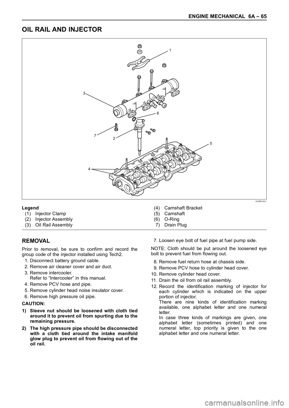
OIL RAIL AND INJECTOR
REMOVAL
Prior to removal, be sure to confirm and record the
group code of the injector installed using Tech2.
1. Disconnect battery ground cable.
2. Remove air cleaner cover and air duct.
3. Remove intercooler.
Refer to “Intercooler” in this manual.
4. Remove PCV hose and pipe.
5. Remove cylinder head noise insulator cover.
6. Remove high pressure oil pipe.
CAUTION:
1) Sleeve nut should be loosened with cloth tied
around it to prevent oil from spurting due to the
remaining pressure.
2) The high pressure pipe should be disconnected
with a cloth tied around the intake manifold
glow plug to prevent oil from flowing out of the
oil rail.7. Loosen eye bolt of fuel pipe at fuel pump side.
NOTE: Cloth should be put around the loosened eye
bolt to prevent fuel from flowing out.
8. Remove fuel return hose at chassis side.
9. Remove PCV hose to cylinder head cover.
10. Remove cylinder head cover.
11. Drain the oil from oil rail assembly.
12. Record the identification marking of injector for
each cylinder which is indicated on the upper
portion of injector.
There are nine kinds of identification marking
available, one alphabet letter and one numeral
letter.
In case three kinds of markings are given, one
alphabet letter (sometimes printed) and one
numeral letter, top priority is given to the one
alphabet letter and one numeral letter.
1
6
27
3
5
4
012RW102-1
Legend
(1) Injector Clamp
(2) Injector Assembly
(3) Oil Rail Assembly(4) Camshaft Bracket
(5) Camshaft
(6) O-Ring
7) Drain Plug