Page 4949 of 6000
6E–292
ENGINE DRIVEABILITY AND EMISSIONS
Crankshaft Position (CKP)
Sensor
Removal Procedure
1. Disconnect the negative battery cable.
2. Disconnect the electrical connector to the CKP
sensor.
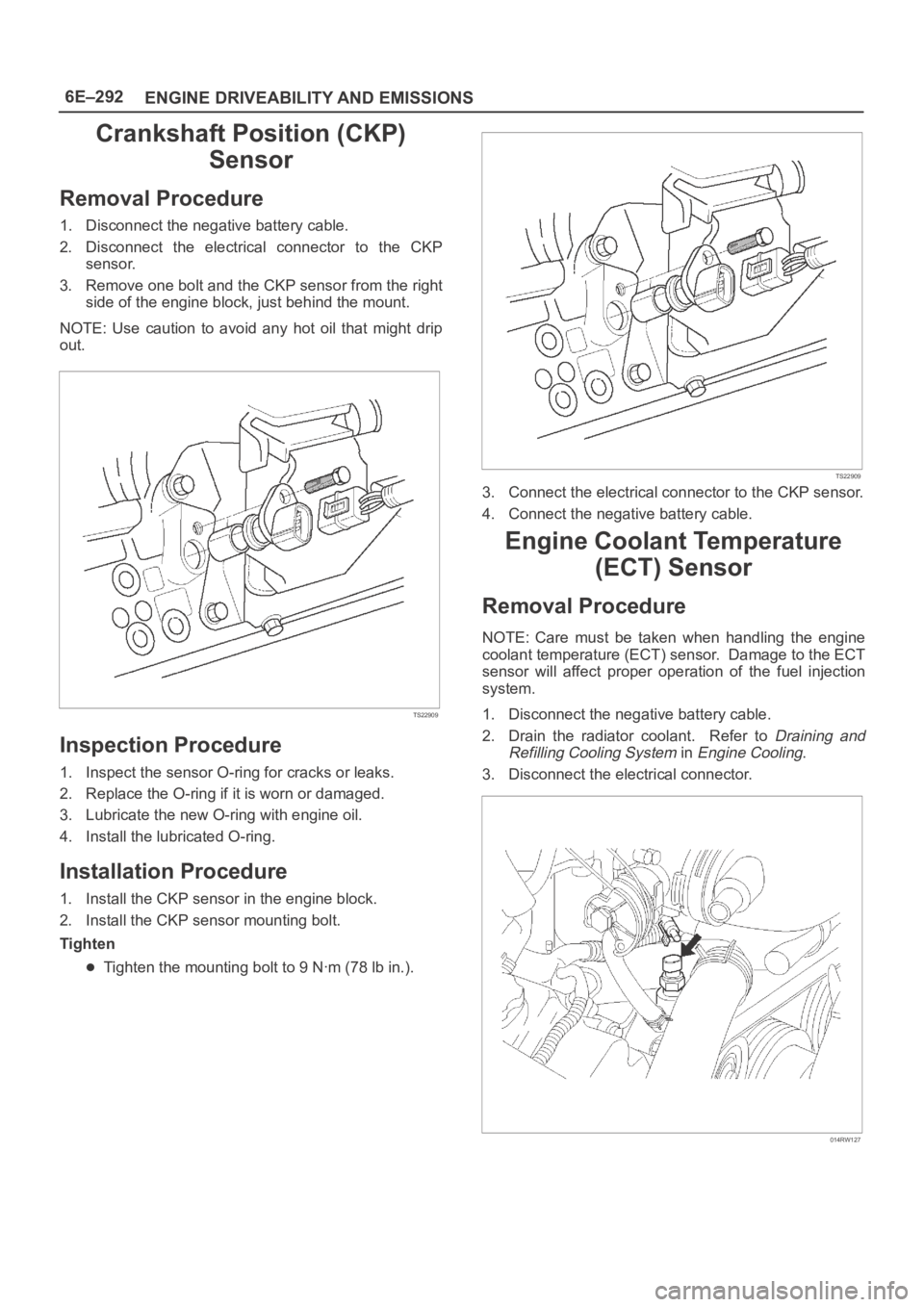
3. Remove one bolt and the CKP sensor from the right
side of the engine block, just behind the mount.
NOTE: Use caution to avoid any hot oil that might drip
out.
TS22909
Inspection Procedure
1. Inspect the sensor O-ring for cracks or leaks.
2. Replace the O-ring if it is worn or damaged.
3. Lubricate the new O-ring with engine oil.
4. Install the lubricated O-ring.
Installation Procedure
1. Install the CKP sensor in the engine block.
2. Install the CKP sensor mounting bolt.
Tighten
Tighten the mounting bolt to 9 Nꞏm (78 lb in.).
TS22909
3. Connect the electrical connector to the CKP sensor.
4. Connect the negative battery cable.
Engine Coolant Temperature
(ECT) Sensor
Removal Procedure
NOTE: Care must be taken when handling the engine
coolant temperature (ECT) sensor. Damage to the ECT
sensor will affect proper operation of the fuel injection
system.
1. Disconnect the negative battery cable.
2. Drain the radiator coolant. Refer to
Draining and
Refilling Cooling System
in Engine Cooling.
3. Disconnect the electrical connector.
014RW127
Page 4954 of 6000
6E–297 ENGINE DRIVEABILITY AND EMISSIONS
Mass Air Flow (MAF) Sensor
Removal Procedure
1. Disconnect the negative battery cable.
2. Disconnect the electrical connector from the MAF
sensor.
TS23740
3. Loosen the clamps which secure the intake air duct
and the air cleaner to the MAF sensor.
4. Remove the intake air duct from the MAF sensor.
5. Remove the MAF sensor from the air cleaner.
TS23781
Installation Procedure
1. Install the MAF sensor on the air cleaner with the
clamp.2. Install the intake air duct and the clamp on the MAF
sensor.
TS23781
3. Tighten the clamps to secure the MAF sensor to the
intake air duct and the air cleaner.
4. Connect the MAF electrical connector.
5. Connect the negative battery cable.
Manifold Absolute Pressure
(MAP) Sensor
Removal Procedure
1. Disconnect the negative battery cable.
2. Disconnect the electrical connector from the MAP
sensor.
055RW005
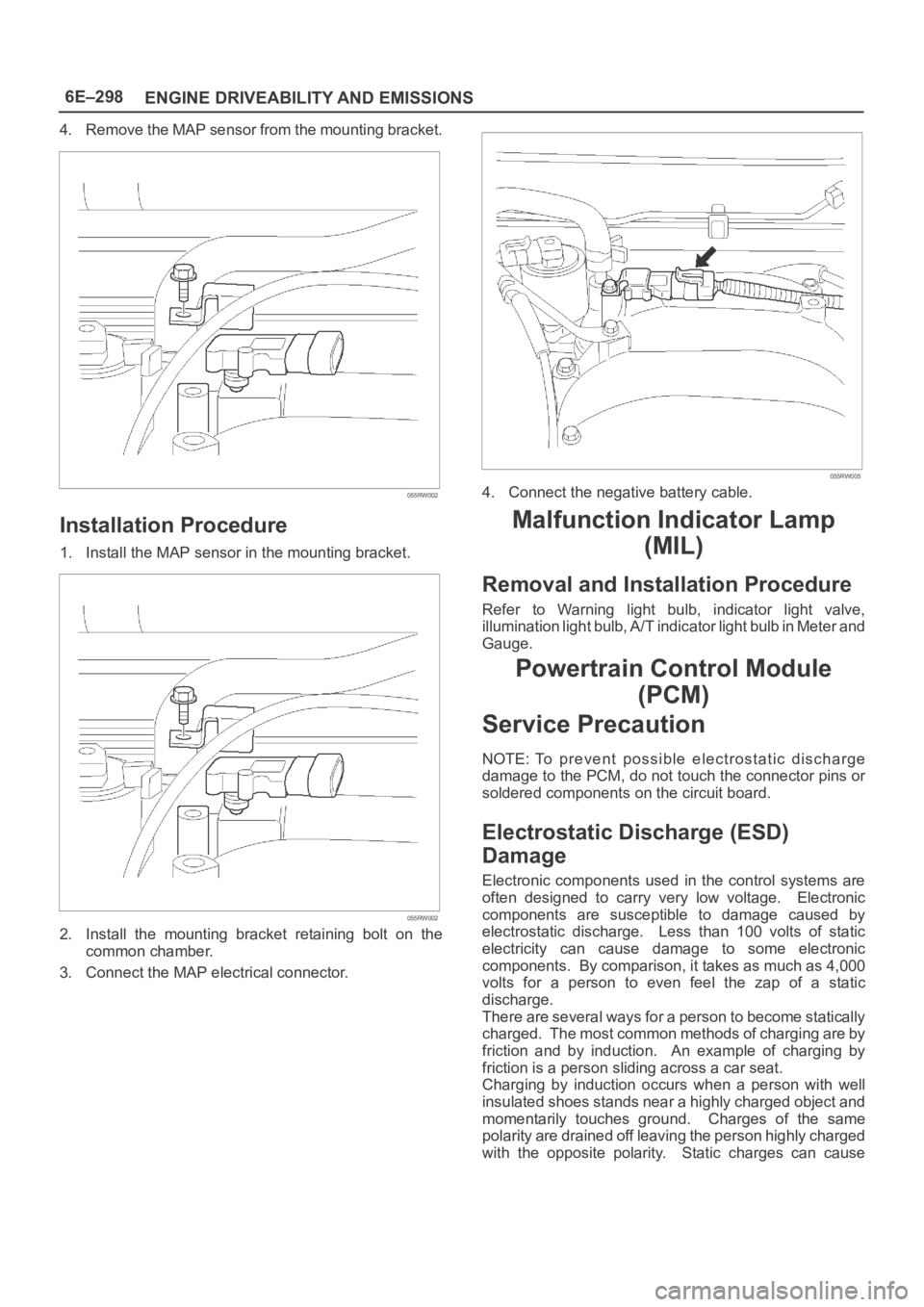
3. Remove the bolt securing the MAP sensor to the
mounting bracket on the common chamber.
Page 4955 of 6000
6E–298
ENGINE DRIVEABILITY AND EMISSIONS
4. Remove the MAP sensor from the mounting bracket.
055RW002
Installation Procedure
1. Install the MAP sensor in the mounting bracket.
055RW002
2. Install the mounting bracket retaining bolt on the
common chamber.
3. Connect the MAP electrical connector.
055RW005
4. Connect the negative battery cable.
Malfunction Indicator Lamp
(MIL)
Removal and Installation Procedure
Refer to Warning light bulb, indicator light valve,
illumination light bulb, A/T indicator light bulb in Meter and
Gauge.
Powertrain Control Module
(PCM)
Service Precaution
NOTE: To prevent possible electrostatic discharge
damage to the PCM, do not touch the connector pins or
soldered components on the circuit board.
Electrostatic Discharge (ESD)
Damage
Electronic components used in the control systems are
often designed to carry very low voltage. Electronic
components are susceptible to damage caused by
electrostatic discharge. Less than 100 volts of static
electricity can cause damage to some electronic
components. By comparison, it takes as much as 4,000
volts for a person to even feel the zap of a static
discharge.
There are several ways for a person to become statically
charged. The most common methods of charging are by
friction and by induction. An example of charging by
friction is a person sliding across a car seat.
Charging by induction occurs when a person with well
insulated shoes stands near a highly charged object and
momentarily touches ground. Charges of the same
polarity are drained off leaving the person highly charged
with the opposite polarity. Static charges can cause
Page 4961 of 6000
6E–304
ENGINE DRIVEABILITY AND EMISSIONS
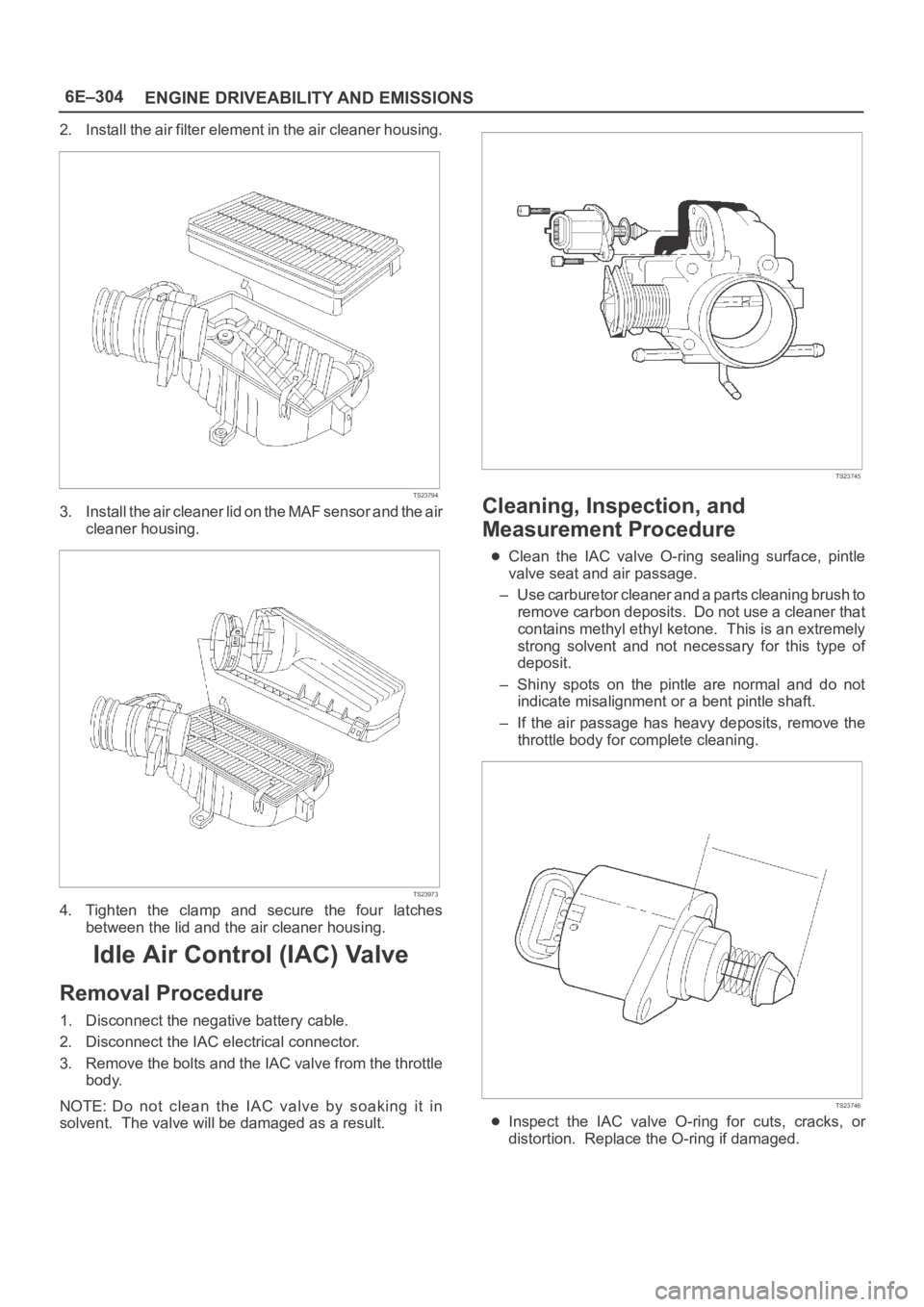
2. Install the air filter element in the air cleaner housing.
TS23794
3. Install the air cleaner lid on the MAF sensor and the air
cleaner housing.
TS23973
4. Tighten the clamp and secure the four latches
between the lid and the air cleaner housing.
Idle Air Control (IAC) Valve
Removal Procedure
1. Disconnect the negative battery cable.
2. Disconnect the IAC electrical connector.
3. Remove the bolts and the IAC valve from the throttle
body.
NOTE: Do not clean the IAC valve by soaking it in
solvent. The valve will be damaged as a result.
TS23745
Cleaning, Inspection, and
Measurement Procedure
Clean the IAC valve O-ring sealing surface, pintle
valve seat and air passage.
– Use carburetor cleaner and a parts cleaning brush to
remove carbon deposits. Do not use a cleaner that
contains methyl ethyl ketone. This is an extremely
strong solvent and not necessary for this type of
deposit.
– Shiny spots on the pintle are normal and do not
indicate misalignment or a bent pintle shaft.
– If the air passage has heavy deposits, remove the
throttle body for complete cleaning.
TS23746
Inspect the IAC valve O-ring for cuts, cracks, or
distortion. Replace the O-ring if damaged.
Page 4962 of 6000
6E–305 ENGINE DRIVEABILITY AND EMISSIONS
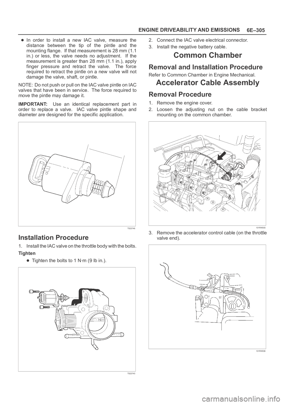
In order to install a new IAC valve, measure the
distance between the tip of the pintle and the
mounting flange. If that measurement is 28 mm (1.1
in.) or less, the valve needs no adjustment. If the
measurement is greater than 28 mm (1.1 in.), apply
finger pressure and retract the valve. The force
required to retract the pintle on a new valve will not
damage the valve, shaft, or pintle.
NOTE: Do not push or pull on the IAC valve pintle on IAC
valves that have been in service. The force required to
move the pintle may damage it.
IMPORTANT:Use an identical replacement part in
order to replace a valve. IAC valve pintle shape and
diameter are designed for the specific application.
TS23746
Installation Procedure
1. Install the IAC valve on the throttle body with the bolts.
Tighten
Tighten the bolts to 1 Nꞏm (9 lb in.).
TS23745
2. Connect the IAC valve electrical connector.
3. Install the negative battery cable.
Common Chamber
Removal and Installation Procedure
Refer to Common Chamber in Engine Mechanical.
Accelerator Cable Assembly
Removal Procedure
1. Remove the engine cover.
2. Loosen the adjusting nut on the cable bracket
mounting on the common chamber.
101RW005
3. Remove the accelerator control cable (on the throttle
valve end).
101RW006
Page 4971 of 6000
6E–314
ENGINE DRIVEABILITY AND EMISSIONS
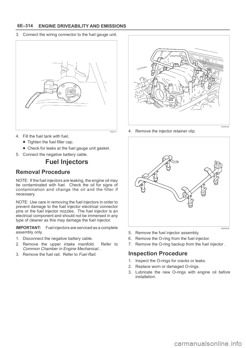
3. Connect the wiring connector to the fuel gauge unit.
TS23771
4. Fill the fuel tank with fuel.
Tighten the fuel filler cap.
Check for leaks at the fuel gauge unit gasket.
5. Connect the negative battery cable.
Fuel Injectors
Removal Procedure
NOTE: If the fuel injectors are leaking, the engine oil may
be contaminated with fuel. Check the oil for signs of
contamination and change the oil and the filter if
necessary.
NOTE: Use care in removing the fuel injectors in order to
prevent damage to the fuel injector electrical connector
pins or the fuel injector nozzles. The fuel injector is an
electrical component and should not be immersed in any
type of cleaner as this may damage the fuel injector.
IMPORTANT:Fuel injectors are serviced as a complete
assembly only.
1. Disconnect the negative battery cable.
2. Remove the upper intake manifold. Refer to
Common Chamber in Engine Mechanical..
3. Remove the fuel rail. Refer to
Fuel Rail.
014RW164
4. Remove the injector retainer clip.
055RW009
5. Remove the fuel injector assembly.
6. Remove the O-ring from the fuel injector.
7. Remove the O-ring backup from the fuel injector .
Inspection Procedure
1. Inspect the O-rings for cracks or leaks.
2. Replace worn or damaged O-rings.
3. Lubricate the new O-rings with engine oil before
installation.
Page 4975 of 6000
6E–318
ENGINE DRIVEABILITY AND EMISSIONS
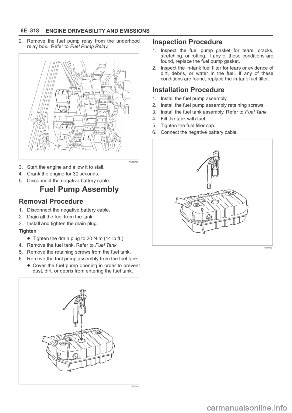
2. Remove the fuel pump relay from the underhood
relay box. Refer to
Fuel Pump Relay.
TS23976R
3. Start the engine and allow it to stall.
4. Crank the engine for 30 seconds.
5. Disconnect the negative battery cable.
Fuel Pump Assembly
Removal Procedure
1. Disconnect the negative battery cable.
2. Drain all the fuel from the tank.
3. Install and tighten the drain plug.
Tighten
Tighten the drain plug to 20 Nꞏm (14 lb ft.).
4. Remove the fuel tank. Refer to
Fuel Tank.
5. Remove the retaining screws from the fuel tank.
6. Remove the fuel pump assembly from the fuel tank.
Cover the fuel pump opening in order to prevent
dust, dirt, or debris from entering the fuel tank.
TS23795
Inspection Procedure
1. Inspect the fuel pump gasket for tears, cracks,
stretching, or rotting. If any of these conditions are
found, replace the fuel pump gasket.
2. Inspect the in-tank fuel filter for tears or evidence of
dirt, debris, or water in the fuel. If any of these
conditions are found, replace the in-tank fuel filter.
Installation Procedure
1. Install the fuel pump assembly.
2. Install the fuel pump assembly retaining screws.
3. Install the fuel tank assembly. Refer to
Fuel Tank.
4. Fill the tank with fuel.
5. Tighten the fuel filler cap.
6. Connect the negative battery cable.
TS23795
Page 4977 of 6000
6E–320
ENGINE DRIVEABILITY AND EMISSIONS
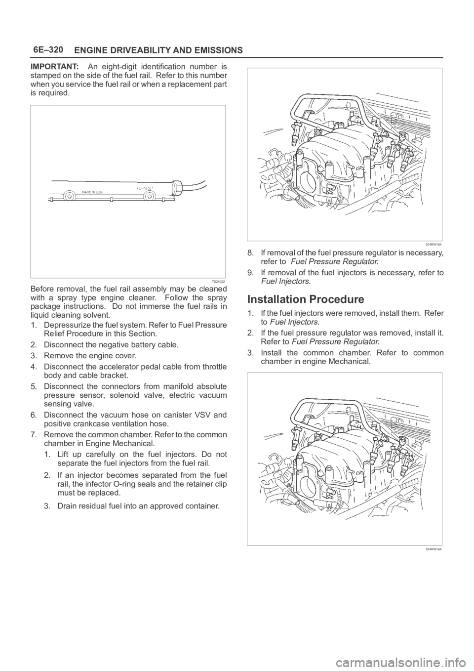
IMPORTANT:An eight-digit identification number is
stamped on the side of the fuel rail. Refer to this number
when you service the fuel rail or when a replacement part
is required.
TS24022
Before removal, the fuel rail assembly may be cleaned
with a spray type engine cleaner. Follow the spray
package instructions. Do not immerse the fuel rails in
liquid cleaning solvent.
1. Depressurize the fuel system. Refer to Fuel Pressure
Relief Procedure in this Section.
2. Disconnect the negative battery cable.
3. Remove the engine cover.
4. Disconnect the accelerator pedal cable from throttle
body and cable bracket.
5. Disconnect the connectors from manifold absolute
pressure sensor, solenoid valve, electric vacuum
sensing valve.
6. Disconnect the vacuum hose on canister VSV and
positive crankcase ventilation hose.
7. Remove the common chamber. Refer to the common
chamber in Engine Mechanical.
1. Lift up carefully on the fuel injectors. Do not
separate the fuel injectors from the fuel rail.
2. If an injector becomes separated from the fuel
rail, the infector O-ring seals and the retainer clip
must be replaced.
3. Drain residual fuel into an approved container.
014RW164
8. If removal of the fuel pressure regulator is necessary,
refer to
Fuel Pressure Regulator.
9. If removal of the fuel injectors is necessary, refer to
Fuel Injectors.
Installation Procedure
1. If the fuel injectors were removed, install them. Refer
to
Fuel Injectors.
2. If the fuel pressure regulator was removed, install it.
Refer to
Fuel Pressure Regulator.
3. Install the common chamber. Refer to common
chamber in engine Mechanical.
014RW164