1998 OPEL FRONTERA reset
[x] Cancel search: resetPage 971 of 6000
6A–15
ENGINE MECHANICAL
Condition CorrectionPossible cause
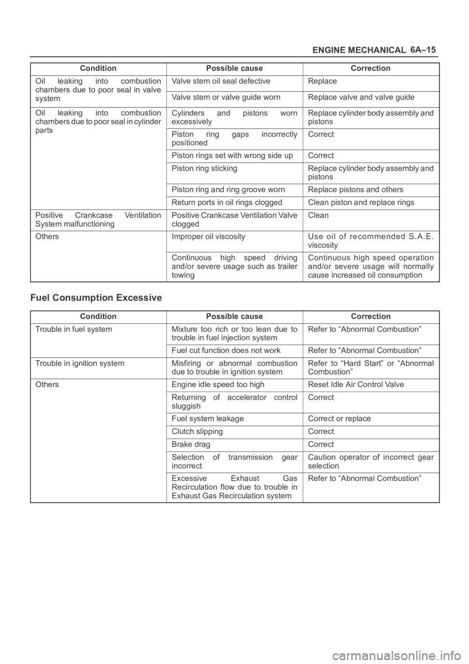
Oil leaking into combustion
chambers due topoor seal in valve
Valve stem oil seal defectiveReplace
chambers due to oor seal in valve
systemValve stem or valve guide wornReplace valve and valve guide
Oil leaking into combustion
chambers due to poor seal in cylinder
t
Cylinders and pistons worn
excessivelyReplace cylinder body assembly and
pistons
partsPiston ring gaps incorrectly
positionedCorrect
Piston rings set with wrong side upCorrect
Piston ring stickingReplace cylinder body assembly and
pistons
Piston ring and ring groove wornReplace pistons and others
Return ports in oil rings cloggedClean piston and replace rings
Positive Crankcase Ventilation
System malfunctioningPositive Crankcase Ventilation Valve
cloggedClean
OthersImproper oil viscosityUse oil of recommended S.A.E.
viscosity
Continuous high speed driving
and/or severe usage such as trailer
towingContinuous high speed operation
and/or severe usage will normally
cause increased oil consumption
Fuel Consumption Excessive
ConditionPossible causeCorrection
Trouble in fuel systemMixture too rich or too lean due to
trouble in fuel injection systemRefer to “Abnormal Combustion”
Fuel cut function does not workRefer to “Abnormal Combustion”
Trouble in ignition systemMisfiring or abnormal combustion
due to trouble in ignition systemRefer to “Hard Start” or “Abnormal
Combustion”
OthersEngine idle speed too highReset Idle Air Control Valve
Returning of accelerator control
sluggishCorrect
Fuel system leakageCorrect or replace
Clutch slippingCorrect
Brake dragCorrect
Selection of transmission gear
incorrectCaution operator of incorrect gear
selection
Excessive Exhaust Gas
Recirculation flow due to trouble in
Exhaust Gas Recirculation systemRefer to “Abnormal Combustion”
Page 1120 of 6000
6E–3 ENGINE DRIVEABILITY AND EMISSIONS
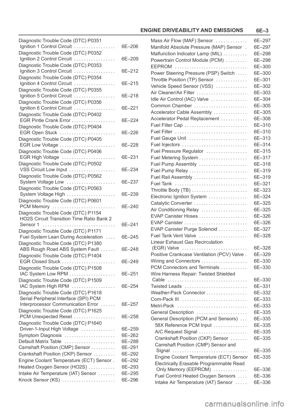
Diagnostic Trouble Code (DTC) P0351
Ignition 1 Control Circuit 6E–206. . . . . . . . . . . . . . . . .
Diagnostic Trouble Code (DTC) P0352
Ignition 2 Control Circuit 6E–209. . . . . . . . . . . . . . . . .
Diagnostic Trouble Code (DTC) P0353
Ignition 3 Control Circuit 6E–212. . . . . . . . . . . . . . . . .
Diagnostic Trouble Code (DTC) P0354
Ignition 4 Control Circuit 6E–215. . . . . . . . . . . . . . . . .
Diagnostic Trouble Code (DTC) P0355
Ignition 5 Control Circuit 6E–218. . . . . . . . . . . . . . . . .
Diagnostic Trouble Code (DTC) P0356
Ignition 6 Control Circuit 6E–221. . . . . . . . . . . . . . . . .
Diagnostic Trouble Code (DTC) P0402
EGR Pintle Crank Error 6E–224. . . . . . . . . . . . . . . . . .
Diagnostic Trouble Code (DTC) P0404
EGR Open Stuck 6E–226. . . . . . . . . . . . . . . . . . . . . . .
Diagnostic Trouble Code (DTC) P0405
EGR Low Voltage 6E–228. . . . . . . . . . . . . . . . . . . . . . .
Diagnostic Trouble Code (DTC) P0406
EGR High Voltage 6E–231. . . . . . . . . . . . . . . . . . . . . .
Diagnostic Trouble Code (DTC) P0502
VSS Circuit Low Input 6E–234. . . . . . . . . . . . . . . . . . .
Diagnostic Trouble Code (DTC) P0562
System Voltage Low 6E–237. . . . . . . . . . . . . . . . . . . .
Diagnostic Trouble Code (DTC) P0563
System Voltage High 6E–239. . . . . . . . . . . . . . . . . . . .
Diagnostic Trouble Code (DTC) P0601
PCM Memory 6E–240. . . . . . . . . . . . . . . . . . . . . . . . . .
Diagnostic Trouble Code (DTC) P1154
HO2S Circuit Transition Time Ratio Bank 2
Sensor 1 6E–241. . . . . . . . . . . . . . . . . . . . . . . . . . . . . .
Diagnostic Trouble Code (DTC) P1171
Fuel System Lean During Acceleration 6E–245. . . .
Diagnostic Trouble Code (DTC) P1380
ABS Rough Road ABS System Fault 6E–248. . . . . .
Diagnostic Trouble Code (DTC) P1404
EGR Closed Stuck 6E–249. . . . . . . . . . . . . . . . . . . . . .
Diagnostic Trouble Code (DTC) P1508
IAC System Low RPM 6E–251. . . . . . . . . . . . . . . . . . .
Diagnostic Trouble Code (DTC) P1509
IAC System High RPM 6E–254. . . . . . . . . . . . . . . . . .
Diagnostic Trouble Code (DTC) P1618
Serial Peripheral Interface (SPI) PCM
Interprocessor Communication Error 6E–257. . . . . .
Diagnostic Trouble Code (DTC) P1625
PCM Unexpected Reset 6E–258. . . . . . . . . . . . . . . . .
Diagnostic Trouble Code (DTC) P1640
Driver-1-Input High Voltage 6E–259. . . . . . . . . . . . . .
Symptom Diagnosis 6E–262. . . . . . . . . . . . . . . . . . . . .
Default Matrix Table 6E–288. . . . . . . . . . . . . . . . . . . . .
Camshaft Position (CMP) Sensor 6E–291. . . . . . . . . .
Crankshaft Position (CKP) Sensor 6E–292. . . . . . . . .
Engine Coolant Temperature (ECT) Sensor 6E–292.
Heated Oxygen Sensor (HO2S) 6E–293. . . . . . . . . . .
Intake Air Temperature (IAT) Sensor 6E–295. . . . . . .
Knock Sensor (KS) 6E–296. . . . . . . . . . . . . . . . . . . . . . Mass Air Flow (MAF) Sensor 6E–297. . . . . . . . . . . . .
Manifold Absolute Pressure (MAP) Sensor 6E–297.
Malfunction Indicator Lamp (MIL) 6E–298. . . . . . . . . .
Powertrain Control Module (PCM) 6E–298. . . . . . . . .
EEPROM 6E–300. . . . . . . . . . . . . . . . . . . . . . . . . . . . . .
Power Steering Pressure (PSP) Switch 6E–300
. . . .
Throttle Position (TP) Sensor 6E–301. . . . . . . . . . . . .
Vehicle Speed Sensor (VSS) 6E–302. . . . . . . . . . . . .
Air Cleaner/Air Filter 6E–303. . . . . . . . . . . . . . . . . . . . .
Idle Air Control (IAC) Valve 6E–304. . . . . . . . . . . . . . .
Common Chamber 6E–305. . . . . . . . . . . . . . . . . . . . . .
Accelerator Cable Assembly 6E–305. . . . . . . . . . . . . .
Accelerator Pedal Replacement 6E–308. . . . . . . . . . .
Fuel Filter Cap 6E–310. . . . . . . . . . . . . . . . . . . . . . . . . .
Fuel Filter 6E–310. . . . . . . . . . . . . . . . . . . . . . . . . . . . . .
Fuel Gauge Unit 6E–313. . . . . . . . . . . . . . . . . . . . . . . .
Fuel Injectors 6E–314. . . . . . . . . . . . . . . . . . . . . . . . . . .
Fuel Pressure Regulator 6E–315. . . . . . . . . . . . . . . . .
Fuel Metering System 6E–317. . . . . . . . . . . . . . . . . . . .
Fuel Pump Assembly 6E–318. . . . . . . . . . . . . . . . . . . .
Fuel Pump Relay 6E–319. . . . . . . . . . . . . . . . . . . . . . . .
Fuel Rail Assembly 6E–319. . . . . . . . . . . . . . . . . . . . . .
Fuel Tank 6E–321. . . . . . . . . . . . . . . . . . . . . . . . . . . . . .
Throttle Body (TB) 6E–323. . . . . . . . . . . . . . . . . . . . . . .
Electronic Ignition System 6E–324. . . . . . . . . . . . . . . .
Catalytic Converter 6E–325. . . . . . . . . . . . . . . . . . . . . .
Air Conditioning Relay 6E–325. . . . . . . . . . . . . . . . . . .
EVAP Canister Hoses 6E–326. . . . . . . . . . . . . . . . . . . .
EVAP Canister 6E–326. . . . . . . . . . . . . . . . . . . . . . . . . .
EVAP Canister Purge Solenoid 6E–327. . . . . . . . . . . .
Fuel Tank Vent Valve 6E–328. . . . . . . . . . . . . . . . . . . .
Linear Exhaust Gas Recirculation
(EGR) Valve 6E–328. . . . . . . . . . . . . . . . . . . . . . . . . . .
Positive Crankcase Ventilation (PCV) Valve 6E–329.
Wiring and Connectors 6E–330. . . . . . . . . . . . . . . . . . .
PCM Connectors and Terminals 6E–330. . . . . . . . . . .
Wire Harness Repair: Twisted Shielded
Cable 6E–330. . . . . . . . . . . . . . . . . . . . . . . . . . . . . . . . .
Twisted Leads 6E–331. . . . . . . . . . . . . . . . . . . . . . . . . .
Weather-Pack Connector 6E–332. . . . . . . . . . . . . . . . .
Com-Pack III 6E–333. . . . . . . . . . . . . . . . . . . . . . . . . . .
Metri-Pack 6E–333. . . . . . . . . . . . . . . . . . . . . . . . . . . . .
General Description 6E–335. . . . . . . . . . . . . . . . . . . . .
General Description (PCM and Sensors) 6E–335. . .
58X Reference PCM Input 6E–335. . . . . . . . . . . . . .
A/C Request Signal 6E–335. . . . . . . . . . . . . . . . . . . .
Crankshaft Position (CKP) Sensor 6E–335. . . . . . .
Camshaft Position (CMP) Sensor and
Signal 6E–335. . . . . . . . . . . . . . . . . . . . . . . . . . . . . . .
Engine Coolant Temperature (ECT) Sensor 6E–335
Electrically Erasable Programmable Read
Only Memory (EEPROM) 6E–336. . . . . . . . . . . . . .
Fuel Control Heated Oxygen Sensors 6E–336. . . .
Intake Air Temperature (IAT) Sensor 6E–336. . . . .
Page 1159 of 6000
6E–42
ENGINE DRIVEABILITY AND EMISSIONS
Intermittent Malfunction Indicator Lamp
In the case of an “intermittent” fault, the MIL (“Check
Engine” lamp) may illuminate and then (after three trips)
go “OFF”. However, the corresponding diagnostic trouble
code will be stored in the memory. When unexpected
diagnostic trouble codes appear, check for an intermittent
malfunction.
A diagnostic trouble code may reset. Consult the
“Diagnostic Aids” associated with the diagnostic trouble
code. A physical inspection of the applicable sub-system
most often will resolve the problem.
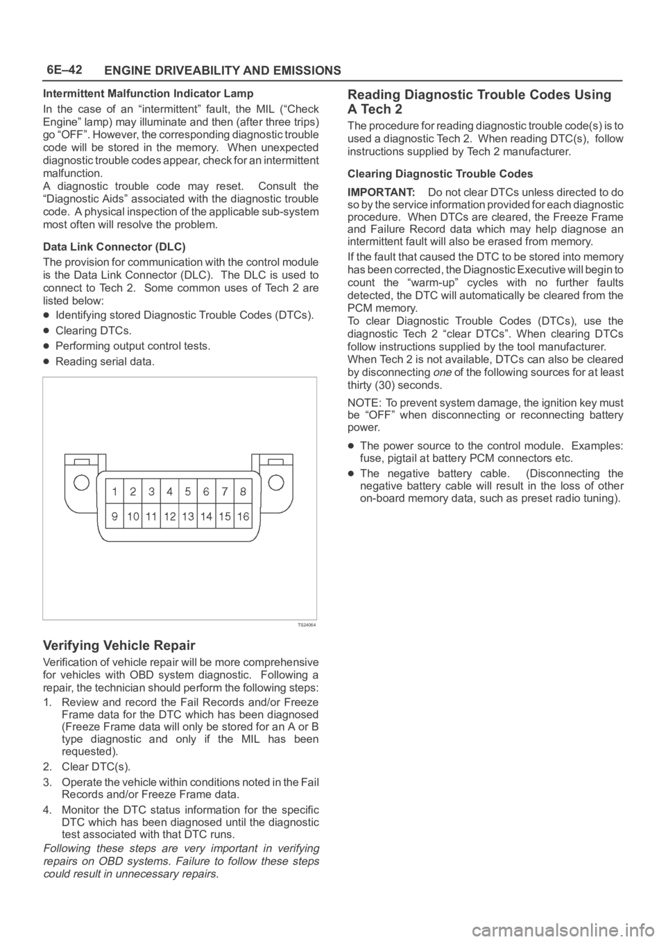
Data Link Connector (DLC)
The provision for communication with the control module
is the Data Link Connector (DLC). The DLC is used to
connect to Tech 2. Some common uses of Tech 2 are
listed below:
Identifying stored Diagnostic Trouble Codes (DTCs).
Clearing DTCs.
Performing output control tests.
Reading serial data.
TS24064
Verifying Vehicle Repair
Verification of vehicle repair will be more comprehensive
for vehicles with OBD system diagnostic. Following a
repair, the technician should perform the following steps:
1. Review and record the Fail Records and/or Freeze
Frame data for the DTC which has been diagnosed
(Freeze Frame data will only be stored for an A or B
type diagnostic and only if the MIL has been
requested).
2. Clear DTC(s).
3. Operate the vehicle within conditions noted in the Fail
Records and/or Freeze Frame data.
4. Monitor the DTC status information for the specific
DTC which has been diagnosed until the diagnostic
test associated with that DTC runs.
Following these steps are very important in verifying
repairs on OBD systems. Failure to follow these steps
could result in unnecessary repairs.
Reading Diagnostic Trouble Codes Using
A Tech 2
The procedure for reading diagnostic trouble code(s) is to
used a diagnostic Tech 2. When reading DTC(s), follow
instructions supplied by Tech 2 manufacturer.
Clearing Diagnostic Trouble Codes
IMPORTANT:Do not clear DTCs unless directed to do
so by the service information provided for each diagnostic
procedure. When DTCs are cleared, the Freeze Frame
and Failure Record data which may help diagnose an
intermittent fault will also be erased from memory.
If the fault that caused the DTC to be stored into memory
has been corrected, the Diagnostic Executive will begin to
count the “warm-up” cycles with no further faults
detected, the DTC will automatically be cleared from the
PCM memory.
To clear Diagnostic Trouble Codes (DTCs), use the
diagnostic Tech 2 “clear DTCs”. When clearing DTCs
follow instructions supplied by the tool manufacturer.
When Tech 2 is not available, DTCs can also be cleared
by disconnecting
one of the following sources for at least
thirty (30) seconds.
NOTE: To prevent system damage, the ignition key must
be “OFF” when disconnecting or reconnecting battery
power.
The power source to the control module. Examples:
fuse, pigtail at battery PCM connectors etc.
The negative battery cable. (Disconnecting the
negative battery cable will result in the loss of other
on-board memory data, such as preset radio tuning).
Page 1166 of 6000
6E–49 ENGINE DRIVEABILITY AND EMISSIONS
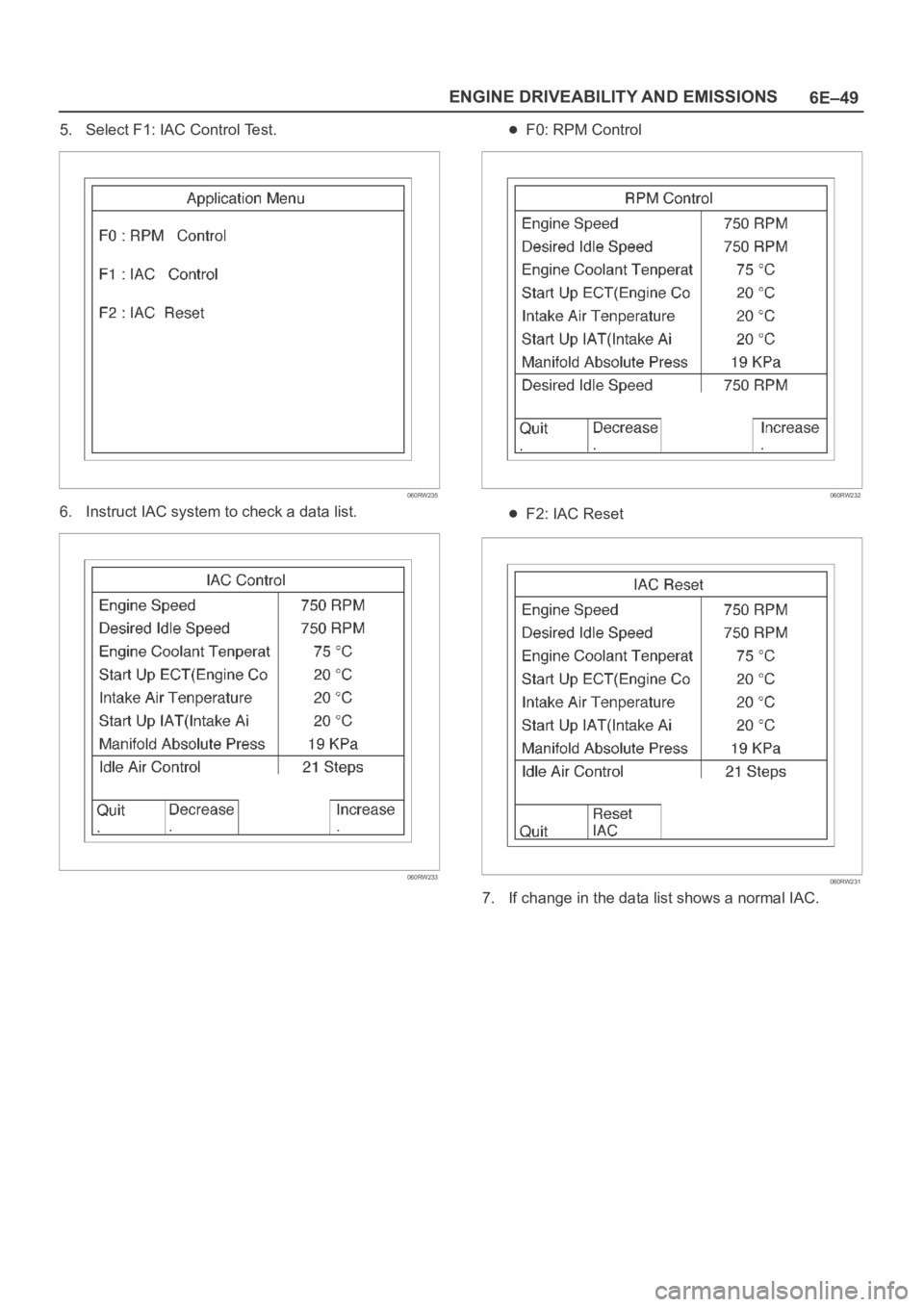
5. Select F1: IAC Control Test.
060RW235
6. Instruct IAC system to check a data list.
060RW233
F0: RPM Control
060RW232
F2: IAC Reset
060RW231
7. If change in the data list shows a normal IAC.
Page 1185 of 6000
6E–68
ENGINE DRIVEABILITY AND EMISSIONS
Exhaust Gas Recirculation (EGR)
Diagnosis (For except EXPORT and
SOUTH AFRICA)
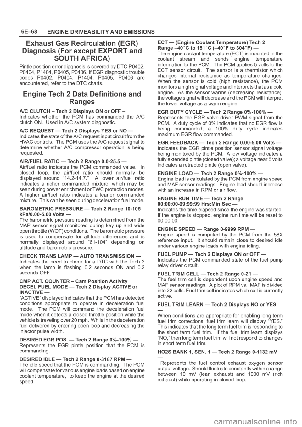
Pintle position error diagnosis is covered by DTC P0402,
P0404, P1404, P0405, P0406. If EGR diagnostic trouble
codes P0402, P0404, P1404, P0405, P0406 are
encountered, refer to the DTC charts.
Engine Tech 2 Data Definitions and
Ranges
A/C CLUTCH – Tech 2 Displays ON or OFF –
Indicates whether the PCM has commanded the A/C
clutch ON. Used in A/C system diagnostic.
A/C REQUEST — Tech 2 Displays YES or NO —
Indicates the state of the A/C request input circuit from the
HVAC controls. The PCM uses the A/C request signal to
determine whether A/C compressor operation is being
requested.
AIR/FUEL RATIO — Tech 2 Range 0.0-25.5 —
Air/fuel ratio indicates the PCM commanded value. In
closed loop, the air/fuel ratio should normally be
displayed around “14.2-14.7.” A lower air/fuel ratio
indicates a richer commanded mixture, which may be
seen during power enrichment or TWC protection modes.
A higher air/fuel ratio indicates a leaner commanded
mixture. This can be seen during deceleration fuel mode.
BAROMETRIC PRESSURE — Tech 2 Range 10-105
kPa/0.00-5.00 Volts —
The barometric pressure reading is determined from the
MAP sensor signal monitored during key up and wide
open throttle (WOT) conditions. The barometric pressure
is used to compensate for altitude differences and is
normally displayed around “61-104” depending on
altitude and barometric pressure.
CHECK TRANS LAMP — AUTO TRANSMISSION —
Indicates the need to check for a DTC with the Tech 2
when the lamp is flashing 0.2 seconds ON and 0.2
seconds OFF.
CMP ACT. COUNTER – Cam Position Activity
DECEL FUEL MODE — Tech 2 Display ACTIVE or
INACTIVE —
“ACTIVE” displayed indicates that the PCM has detected
conditions appropriate to operate in deceleration fuel
mode. The PCM will command the deceleration fuel
mode when it detects a closed throttle position while the
vehicle is traveling over 20 mph. While in the deceleration
fuel delivered by entering open loop and decreasing the
injector pulse width.
DESIRED EGR POS. — Tech 2 Range 0%-100% —
Represents the EGR pintle position that the PCM is
commanding.
DESIRED IDLE — Tech 2 Range 0-3187 RPM —
The idle speed that the PCM is commanding. The PCM
will compensate for various engine loads based on engine
coolant temperature, to keep the engine at the desired
speed.ECT — (Engine Coolant Temperature) Tech 2
Range –40
C to 151C (–40F to 304F) —
The engine coolant temperature (ECT) is mounted in the
coolant stream and sends engine temperature
information to the PCM. The PCM applies 5 volts to the
ECT sensor circuit. The sensor is a thermistor which
changes internal resistance as temperature changes.
When the sensor is cold (high resistance), the PCM
monitors a high signal voltage and interprets that as a cold
engine. As the sensor warms (decreasing resistance),
the voltage signal will decrease and the PCM will interpret
the lower voltage as a warm engine.
EGR DUTY CYCLE — Tech 2 Range 0%-100% —
Represents the EGR valve driver PWM signal from the
PCM. A duty cycle of 0% indicates that no EGR flow is
being commanded; a 100% duty cycle indicates
maximum EGR flow commanded.
EGR FEEDBACK — Tech 2 Range 0.00-5.00 Volts —
Indicates the EGR pintle position sensor signal voltage
being monitored by the PCM. A low voltage indicates a
fully extended pintle (closed valve); a voltage near 5 volts
indicates a retracted pintle (open valve).
ENGINE LOAD — Tech 2 Range 0%-100% —
Engine load is calculated by the PCM from engine speed
and MAF sensor readings. Engine load should increase
with an increase in RPM or air flow.
ENGINE RUN TIME — Tech 2 Range
00:00:00-99:99:99 Hrs:Min:Sec —
Indicates the time elapsed since the engine was started.
If the engine is stopped, engine run time will be reset to
00:00:00.
ENGINE SPEED — Range 0-9999 RPM —
Engine speed is computed by the PCM from the 58X
reference input. It should remain close to desired idle
under various engine loads with engine idling.
FUEL PUMP — Tech 2 Displays ON or OFF —
Indicates the PCM commanded state of the fuel pump
relay driver circuit.
FUEL TRIM CELL — Tech 2 Range 0-21 —
The fuel trim cell is dependent upon engine speed and
MAF sensor readings. A plot of RPM vs. MAF is divided
into 22 cells. Fuel trim cell indicates which cell is currently
active.
FUEL TRIM LEARN — Tech 2 Displays NO or YES
—
When conditions are appropriate for enabling long term
fuel trim corrections, fuel trim learn will display “YES.”
This indicates that the long term fuel trim is responding to
the short term fuel trim. If the fuel trim learn displays
“NO,” then long term fuel trim will not respond to changes
in short term fuel trim.
HO2S BANK 1, SEN. 1 — Tech 2 Range 0-1132 mV
—
Represents the fuel control exhaust oxygen sensor
output voltage. Should fluctuate constantly within a range
between 10 mV (lean exhaust) and 1000 mV (rich
exhaust) while operating in closed loop.
Page 1188 of 6000
6E–71 ENGINE DRIVEABILITY AND EMISSIONS
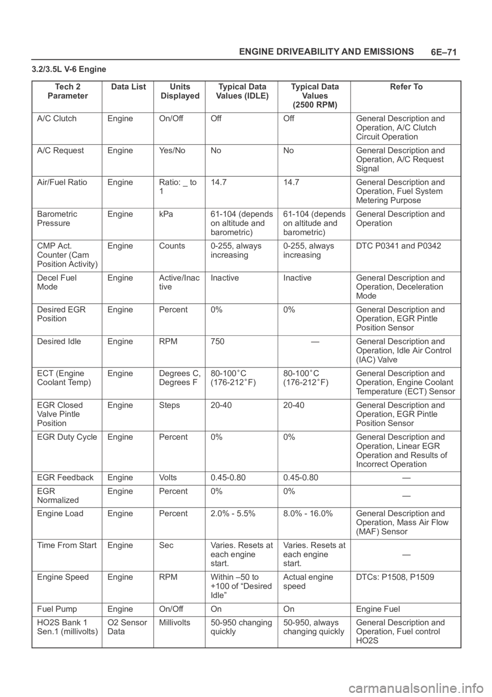
3.2/3.5L V-6 Engine
Te c h 2
Parameter
Data ListUnits
DisplayedTypical Data
Values (IDLE)Typical Data
Va l u e s
(2500 RPM)Refer To
A/C ClutchEngineOn/OffOffOffGeneral Description and
Operation, A/C Clutch
Circuit Operation
A/C RequestEngineYe s / N oNoNoGeneral Description and
Operation, A/C Request
Signal
Air/Fuel RatioEngineRatio: _ to
114.714.7General Description and
Operation, Fuel System
Metering Purpose
Barometric
PressureEnginekPa61-104 (depends
on altitude and
barometric)61-104 (depends
on altitude and
barometric)General Description and
Operation
CMP Act.
Counter (Cam
Position Activity)EngineCounts0-255, always
increasing0-255, always
increasingDTC P0341 and P0342
Decel Fuel
ModeEngineActive/Inac
tiveInactiveInactiveGeneral Description and
Operation, Deceleration
Mode
Desired EGR
PositionEnginePercent0%0%General Description and
Operation, EGR Pintle
Position Sensor
Desired IdleEngineRPM750—General Description and
Operation, Idle Air Control
(IAC) Valve
ECT (Engine
Coolant Temp)EngineDegrees C,
Degrees F80-100C
(176-212
F)
80-100C
(176-212
F)
General Description and
Operation, Engine Coolant
Temperature (ECT) Sensor
EGR Closed
Valve Pintle
PositionEngineSteps20-4020-40General Description and
Operation, EGR Pintle
Position Sensor
EGR Duty CycleEnginePercent0%0%General Description and
Operation, Linear EGR
Operation and Results of
Incorrect Operation
EGR FeedbackEngineVo l t s0.45-0.800.45-0.80—
EGR
NormalizedEnginePercent0%0%—
Engine LoadEnginePercent2.0% - 5.5%8.0% - 16.0%General Description and
Operation, Mass Air Flow
(MAF) Sensor
Time From StartEngineSecVaries. Resets at
each engine
start.Varies. Resets at
each engine
start.
—
Engine SpeedEngineRPMWithin –50 to
+100 of “Desired
Idle”Actual engine
speedDTCs: P1508, P1509
Fuel PumpEngineOn/OffOnOnEngine Fuel
HO2S Bank 1
Sen.1 (millivolts)O2 Sensor
DataMillivolts50-950 changing
quickly50-950, always
changing quicklyGeneral Description and
Operation, Fuel control
HO2S
Page 1210 of 6000
6E–93 ENGINE DRIVEABILITY AND EMISSIONS
Idle Air Control (IAC) System Check
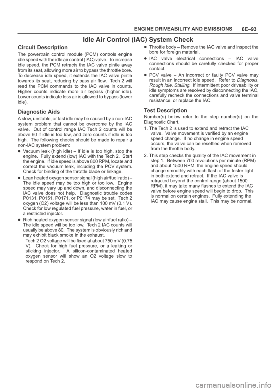
Circuit Description
The powertrain control module (PCM) controls engine
idle speed with the idle air control (IAC) valve. To increase
idle speed, the PCM retracts the IAC valve pintle away
from its seat, allowing more air to bypass the throttle bore.
To decrease idle speed, it extends the IAC valve pintle
towards its seat, reducing by pass air flow. Tech 2 will
read the PCM commands to the IAC valve in counts.
Higher counts indicate more air bypass (higher idle).
Lower counts indicate less air is allowed to bypass (lower
idle).
Diagnostic Aids
A slow, unstable, or fast idle may be caused by a non-IAC
system problem that cannot be overcome by the IAC
valve. Out of control range IAC Tech 2 counts will be
above 60 if idle is too low, and zero counts if idle is too
high. The following checks should be made to repair a
non-IAC system problem:
Vacuum leak (high idle) – If idle is too high, stop the
engine. Fully extend (low) IAC with the Tech 2. Start
the engine. If idle speed is above 800 RPM, locate and
correct the vacuum leak, including the PCV system.
Check for binding of the throttle blade or linkage.
Lean heated oxygen sensor signal (high air/fuel ratio) –
The idle speed may be too high or too low. Engine
speed may vary up and down, and disconnecting the
IAC valve does not help. Diagnostic trouble codes
P0131, P0151, P0171, or P0174 may be set. Tech 2
oxygen (O2) voltage will be less than 100 mV (0.1 V).
Check for low regulated fuel pressure, water in fuel, or
a restricted injector.
Rich heated oxygen sensor signal (low air/fuel ratio) –
The idle speed will be too low. Tech 2 IAC counts will
usually be above 80. The system is obviously rich and
may exhibit black smoke in the exhaust.
Tech 2 O2 voltage will be fixed at about 750 mV (0.75
V). Check for high fuel pressure, or a leaking or
sticking injector. A silicon-contaminated heated
oxygen sensor will show an O2 voltage slow to
respond on Tech 2.
Throttle body – Remove the IAC valve and inspect the
bore for foreign material.
IAC valve electrical connections – IAC valve
connections should be carefully checked for proper
contact.
PCV valve – An incorrect or faulty PCV valve may
result in an incorrect idle speed. Refer to
Diagnosis,
Rough Idle, Stalling.
If intermittent poor driveability or
idle symptoms are resolved by disconnecting the IAC,
carefully recheck the connections and valve terminal
resistance, or replace the IAC.
Test Description
Number(s) below refer to the step number(s) on the
Diagnostic Chart.
1. The Tech 2 is used to extend and retract the IAC
valve. Valve movement is verified by an engine
speed change. If no change in engine speed
occurs, the valve can be resettled when removed
from the throttle body.
2. This step checks the quality of the IAC movement in
step 1. Between 700 revolutions per minute (RPM)
and about 1500 RPM, the engine speed should
change smoothly with each flash of the tester light
in both extend and retract. If the IAC valve is
retracted beyond the control range (about 1500
RPM), it may take many flashes to extend the IAC
valve before engine speed will begin to drop. This
is normal on certain engines. Fully extending the
IAC may cause engine stall. This may be normal.
Page 1288 of 6000
6E–171 ENGINE DRIVEABILITY AND EMISSIONS
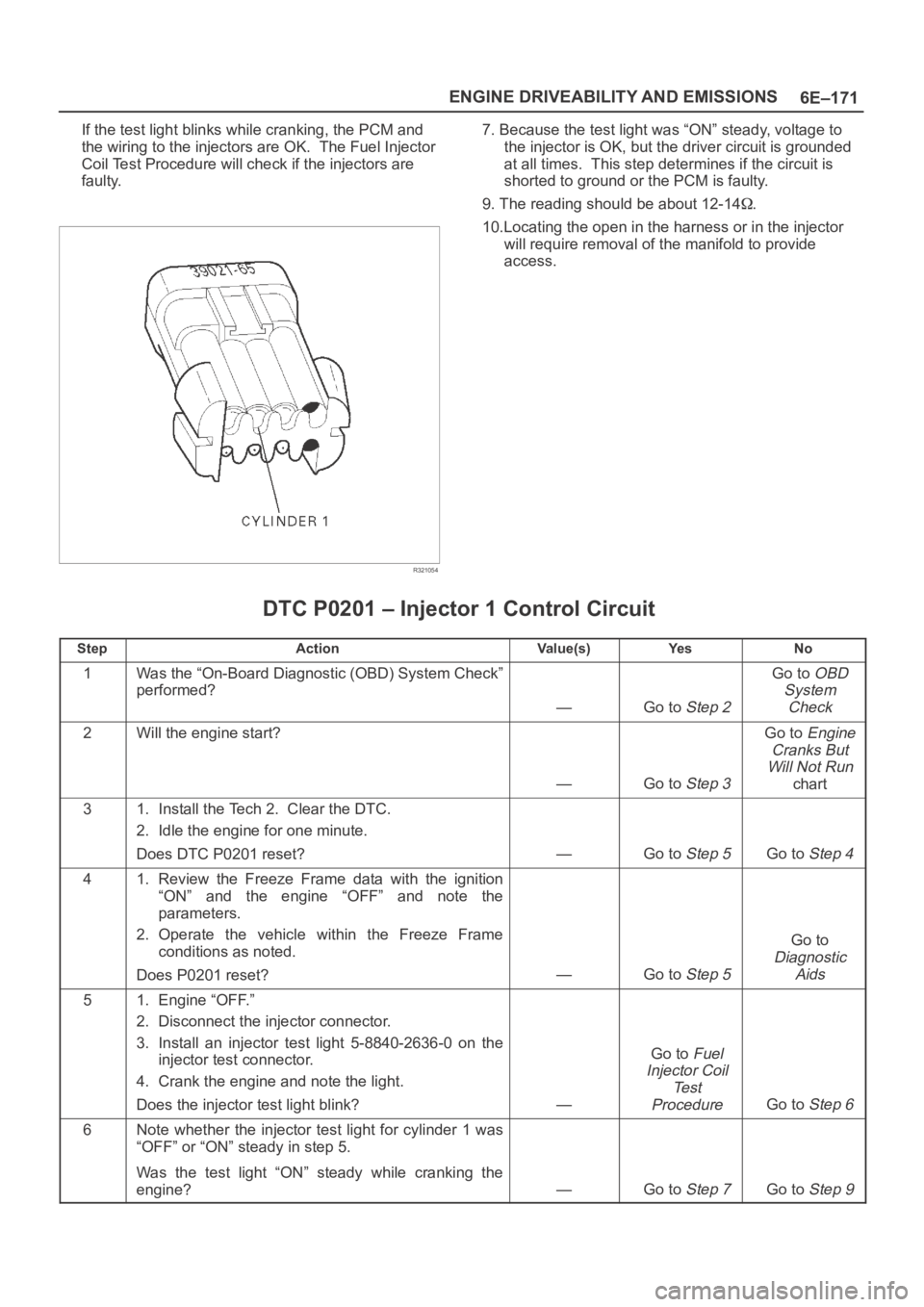
If the test light blinks while cranking, the PCM and
the wiring to the injectors are OK. The Fuel Injector
Coil Test Procedure will check if the injectors are
faulty.
R321054
7. Because the test light was “ON” steady, voltage to
the injector is OK, but the driver circuit is grounded
at all times. This step determines if the circuit is
shorted to ground or the PCM is faulty.
9. The reading should be about 12-14
.
10.Locating the open in the harness or in the injector
will require removal of the manifold to provide
access.
DTC P0201 – Injector 1 Control Circuit
StepActionVa l u e ( s )Ye sNo
1Was the “On-Board Diagnostic (OBD) System Check”
performed?
—Go to Step 2
Go to OBD
System
Check
2Will the engine start?
—Go to Step 3
Go to Engine
Cranks But
Will Not Run
chart
31. Install the Tech 2. Clear the DTC.
2. Idle the engine for one minute.
Does DTC P0201 reset?
—Go to Step 5Go to Step 4
41. Review the Freeze Frame data with the ignition
“ON” and the engine “OFF” and note the
parameters.
2. Operate the vehicle within the Freeze Frame
conditions as noted.
Does P0201 reset?
—Go to Step 5
Go to
Diagnostic
Aids
51. Engine “OFF.”
2. Disconnect the injector connector.
3. Install an injector test light 5-8840-2636-0 on the
injector test connector.
4. Crank the engine and note the light.
Does the injector test light blink?
—
Go to Fuel
Injector Coil
Te s t
Procedure
Go to Step 6
6Note whether the injector test light for cylinder 1 was
“OFF” or “ON” steady in step 5.
Was the test light “ON” steady while cranking the
engine?
—Go to Step 7Go to Step 9