1998 OPEL FRONTERA reset
[x] Cancel search: resetPage 1291 of 6000
6E–174
ENGINE DRIVEABILITY AND EMISSIONS
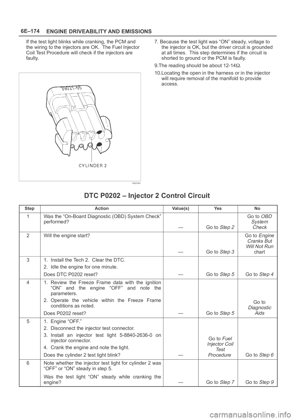
If the test light blinks while cranking, the PCM and
the wiring to the injectors are OK. The Fuel Injector
Coil Test Procedure will check if the injectors are
faulty.
R321055
7. Because the test light was “ON” steady, voltage to
the injector is OK, but the driver circuit is grounded
at all times. This step determines if the circuit is
shorted to ground or the PCM is faulty.
9.The reading should be about 12-14
.
10.Locating the open in the harness or in the injector
will require removal of the manifold to provide
access.
DTC P0202 – Injector 2 Control Circuit
StepActionVa l u e ( s )Ye sNo
1Was the “On-Board Diagnostic (OBD) System Check”
performed?
—Go to Step 2
Go to OBD
System
Check
2Will the engine start?
—Go to Step 3
Go to Engine
Cranks But
Will Not Run
chart
31. Install the Tech 2. Clear the DTC.
2. Idle the engine for one minute.
Does DTC P0202 reset?
—Go to Step 5Go to Step 4
41. Review the Freeze Frame data with the ignition
“ON” and the engine “OFF” and note the
parameters.
2. Operate the vehicle within the Freeze Frame
conditions as noted.
Does P0202 reset?
—Go to Step 5
Go to
Diagnostic
Aids
51. Engine “OFF.”
2. Disconnect the injector test connector.
3. Install an injector test light 5-8840-2636-0 on
injector connector.
4. Crank the engine and note the light.
Does the cylinder 2 test light blink?
—
Go to Fuel
Injector Coil
Te s t
Procedure
Go to Step 6
6Note whether the injector test light for cylinder 2 was
“OFF” or “ON” steady in step 5.
Was the test light “ON” steady while cranking the
engine?
—Go to Step 7Go to Step 9
Page 1294 of 6000
6E–177 ENGINE DRIVEABILITY AND EMISSIONS
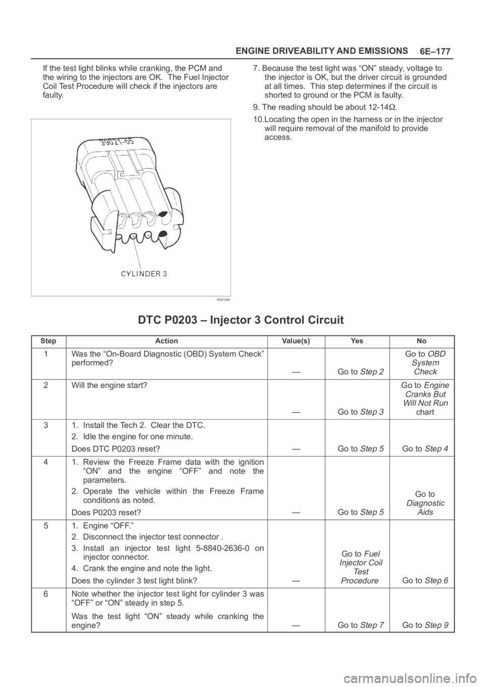
If the test light blinks while cranking, the PCM and
the wiring to the injectors are OK. The Fuel Injector
Coil Test Procedure will check if the injectors are
faulty.
R321056
7. Because the test light was “ON” steady, voltage to
the injector is OK, but the driver circuit is grounded
at all times. This step determines if the circuit is
shorted to ground or the PCM is faulty.
9. The reading should be about 12-14
.
10.Locating the open in the harness or in the injector
will require removal of the manifold to provide
access.
DTC P0203 – Injector 3 Control Circuit
StepActionVa l u e ( s )Ye sNo
1Was the “On-Board Diagnostic (OBD) System Check”
performed?
—Go to Step 2
Go to OBD
System
Check
2Will the engine start?
—Go to Step 3
Go to Engine
Cranks But
Will Not Run
chart
31. Install the Tech 2. Clear the DTC.
2. Idle the engine for one minute.
Does DTC P0203 reset?
—Go to Step 5Go to Step 4
41. Review the Freeze Frame data with the ignition
“ON” and the engine “OFF” and note the
parameters.
2. Operate the vehicle within the Freeze Frame
conditions as noted.
Does P0203 reset?
—Go to Step 5
Go to
Diagnostic
Aids
51. Engine “OFF.”
2. Disconnect the injector test connector .
3. Install an injector test light 5-8840-2636-0 on
injector connector.
4. Crank the engine and note the light.
Does the cylinder 3 test light blink?
—
Go to Fuel
Injector Coil
Te s t
Procedure
Go to Step 6
6Note whether the injector test light for cylinder 3 was
“OFF” or “ON” steady in step 5.
Was the test light “ON” steady while cranking the
engine?
—Go to Step 7Go to Step 9
Page 1297 of 6000
6E–180
ENGINE DRIVEABILITY AND EMISSIONS
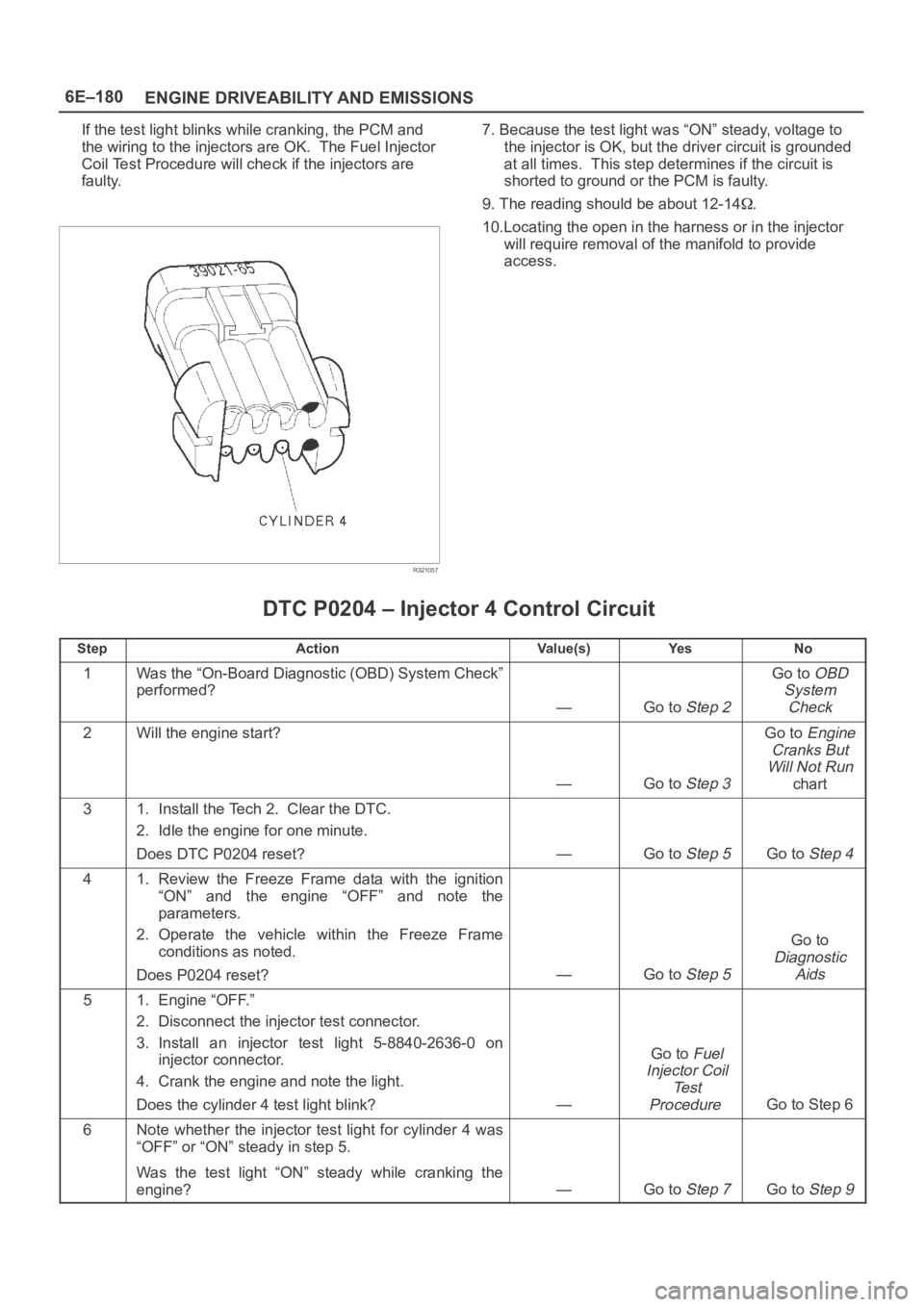
If the test light blinks while cranking, the PCM and
the wiring to the injectors are OK. The Fuel Injector
Coil Test Procedure will check if the injectors are
faulty.
R321057
7. Because the test light was “ON” steady, voltage to
the injector is OK, but the driver circuit is grounded
at all times. This step determines if the circuit is
shorted to ground or the PCM is faulty.
9. The reading should be about 12-14
.
10.Locating the open in the harness or in the injector
will require removal of the manifold to provide
access.
DTC P0204 – Injector 4 Control Circuit
StepActionVa l u e ( s )Ye sNo
1Was the “On-Board Diagnostic (OBD) System Check”
performed?
—Go to Step 2
Go to OBD
System
Check
2Will the engine start?
—Go to Step 3
Go to Engine
Cranks But
Will Not Run
chart
31. Install the Tech 2. Clear the DTC.
2. Idle the engine for one minute.
Does DTC P0204 reset?
—Go to Step 5Go to Step 4
41. Review the Freeze Frame data with the ignition
“ON” and the engine “OFF” and note the
parameters.
2. Operate the vehicle within the Freeze Frame
conditions as noted.
Does P0204 reset?
—Go to Step 5
Go to
Diagnostic
Aids
51. Engine “OFF.”
2. Disconnect the injector test connector.
3. Install an injector test light 5-8840-2636-0 on
injector connector.
4. Crank the engine and note the light.
Does the cylinder 4 test light blink?
—
Go to Fuel
Injector Coil
Te s t
Procedure
Go to Step 6
6Note whether the injector test light for cylinder 4 was
“OFF” or “ON” steady in step 5.
Was the test light “ON” steady while cranking the
engine?
—Go to Step 7Go to Step 9
Page 1300 of 6000
6E–183 ENGINE DRIVEABILITY AND EMISSIONS
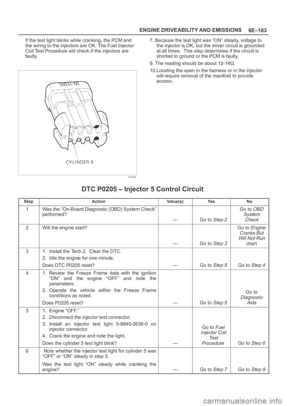
If the test light blinks while cranking, the PCM and
the wiring to the injectors are OK. The Fuel Injector
Coil Test Procedure will check if the injectors are
faulty.
R321058
7. Because the test light was “ON” steady, voltage to
the injector is OK, but the driver circuit is grounded
at all times. This step determines if the circuit is
shorted to ground or the PCM is faulty.
9. The reading should be about 12-14
.
10.Locating the open in the harness or in the injector
will require removal of the manifold to provide
access.
DTC P0205 – Injector 5 Control Circuit
StepActionVa l u e ( s )Ye sNo
1Was the “On-Board Diagnostic (OBD) System Check”
performed?
—Go to Step 2
Go to OBD
System
Check
2Will the engine start?
—Go to Step 3
Go to Engine
Cranks But
Will Not Run
chart
31. Install the Tech 2. Clear the DTC.
2. Idle the engine for one minute.
Does DTC P0205 reset?
—Go to Step 5Go to Step 4
41. Review the Freeze Frame data with the ignition
“ON” and the engine “OFF” and note the
parameters.
2. Operate the vehicle within the Freeze Frame
conditions as noted.
Does P0205 reset?
—Go to Step 5
Go to
Diagnostic
Aids
51. Engine “OFF.”
2. Disconnect the injector test connector.
3. Install an injector test light 5-8840-2636-0 on
injector connector.
4. Crank the engine and note the light.
Does the cylinder 5 test light blink?
—
Go to Fuel
Injector Coil
Te s t
Procedure
Go to Step 6
6 Note whether the injector test light for cylinder 5 was
“OFF” or “ON” steady in step 5.
Was the test light “ON” steady while cranking the
engine?
—Go to Step 7Go to Step 9
Page 1303 of 6000
6E–186
ENGINE DRIVEABILITY AND EMISSIONS
If the test light blinks while cranking, the PCM and
the wiring to the injectors are OK. The Fuel Injector
Coil Test Procedure will check if the injectors are
faulty.
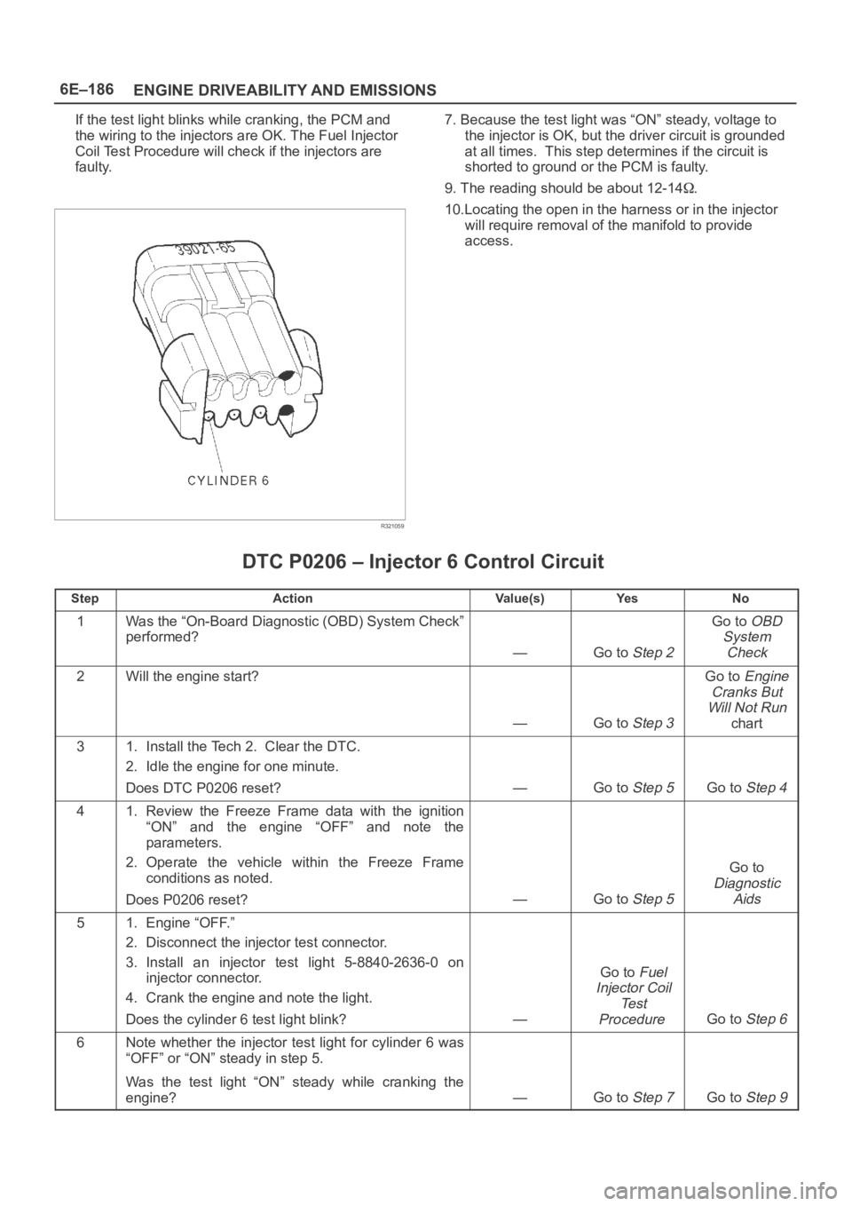
R321059
7. Because the test light was “ON” steady, voltage to
the injector is OK, but the driver circuit is grounded
at all times. This step determines if the circuit is
shorted to ground or the PCM is faulty.
9. The reading should be about 12-14
.
10.Locating the open in the harness or in the injector
will require removal of the manifold to provide
access.
DTC P0206 – Injector 6 Control Circuit
StepActionVa l u e ( s )Ye sNo
1Was the “On-Board Diagnostic (OBD) System Check”
performed?
—Go to Step 2
Go to OBD
System
Check
2Will the engine start?
—Go to Step 3
Go to Engine
Cranks But
Will Not Run
chart
31. Install the Tech 2. Clear the DTC.
2. Idle the engine for one minute.
Does DTC P0206 reset?
—Go to Step 5Go to Step 4
41. Review the Freeze Frame data with the ignition
“ON” and the engine “OFF” and note the
parameters.
2. Operate the vehicle within the Freeze Frame
conditions as noted.
Does P0206 reset?
—Go to Step 5
Go to
Diagnostic
Aids
51. Engine “OFF.”
2. Disconnect the injector test connector.
3. Install an injector test light 5-8840-2636-0 on
injector connector.
4. Crank the engine and note the light.
Does the cylinder 6 test light blink?
—
Go to Fuel
Injector Coil
Te s t
Procedure
Go to Step 6
6Note whether the injector test light for cylinder 6 was
“OFF” or “ON” steady in step 5.
Was the test light “ON” steady while cranking the
engine?
—Go to Step 7Go to Step 9
Page 1367 of 6000
6E–250
ENGINE DRIVEABILITY AND EMISSIONS
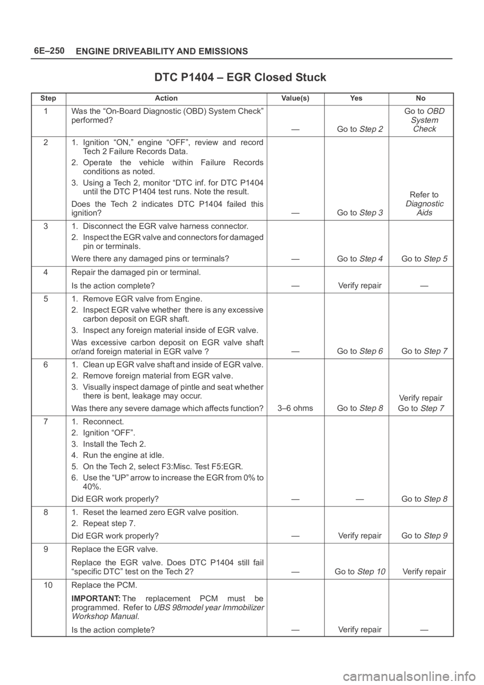
DTC P1404 – EGR Closed Stuck
StepActionVa l u e ( s )Ye sNo
1Was the “On-Board Diagnostic (OBD) System Check”
performed?
—Go to Step 2
Go to OBD
System
Check
21. Ignition “ON,” engine “OFF”, review and record
Tech 2 Failure Records Data.
2. Operate the vehicle within Failure Records
conditions as noted.
3. Using a Tech 2, monitor “DTC inf. for DTC P1404
until the DTC P1404 test runs. Note the result.
Does the Tech 2 indicates DTC P1404 failed this
ignition?
—Go to Step 3
Refer to
Diagnostic
Aids
31. Disconnect the EGR valve harness connector.
2. Inspect the EGR valve and connectors for damaged
pin or terminals.
Were there any damaged pins or terminals?
—Go to Step 4Go to Step 5
4Repair the damaged pin or terminal.
Is the action complete?
—Verify repair—
51. Remove EGR valve from Engine.
2. Inspect EGR valve whether there is any excessive
carbon deposit on EGR shaft.
3. Inspect any foreign material inside of EGR valve.
Was excessive carbon deposit on EGR valve shaft
or/and foreign material in EGR valve ?
—Go to Step 6Go to Step 7
61. Clean up EGR valve shaft and inside of EGR valve.
2. Remove foreign material from EGR valve.
3. Visually inspect damage of pintle and seat whether
there is bent, leakage may occur.
Was there any severe damage which affects function?
3–6 ohmsGo to Step 8
Verify repair
Go to
Step 7
71. Reconnect.
2. Ignition “OFF”.
3. Install the Tech 2.
4. Run the engine at idle.
5. On the Tech 2, select F3:Misc. Test F5:EGR.
6. Use the “UP” arrow to increase the EGR from 0% to
40%.
Did EGR work properly?
——Go to Step 8
81. Reset the learned zero EGR valve position.
2. Repeat step 7.
Did EGR work properly?
—Verify repairGo to Step 9
9Replace the EGR valve.
Replace the EGR valve. Does DTC P1404 still fail
“specific DTC” test on the Tech 2?
—Go to Step 10Verify repair
10Replace the PCM.
IMPORTANT:The replacement PCM must be
programmed. Refer to
UBS 98model year Immobilizer
Workshop Manual.
Is the action complete?—Verify repair—
Page 1374 of 6000
6E–257 ENGINE DRIVEABILITY AND EMISSIONS
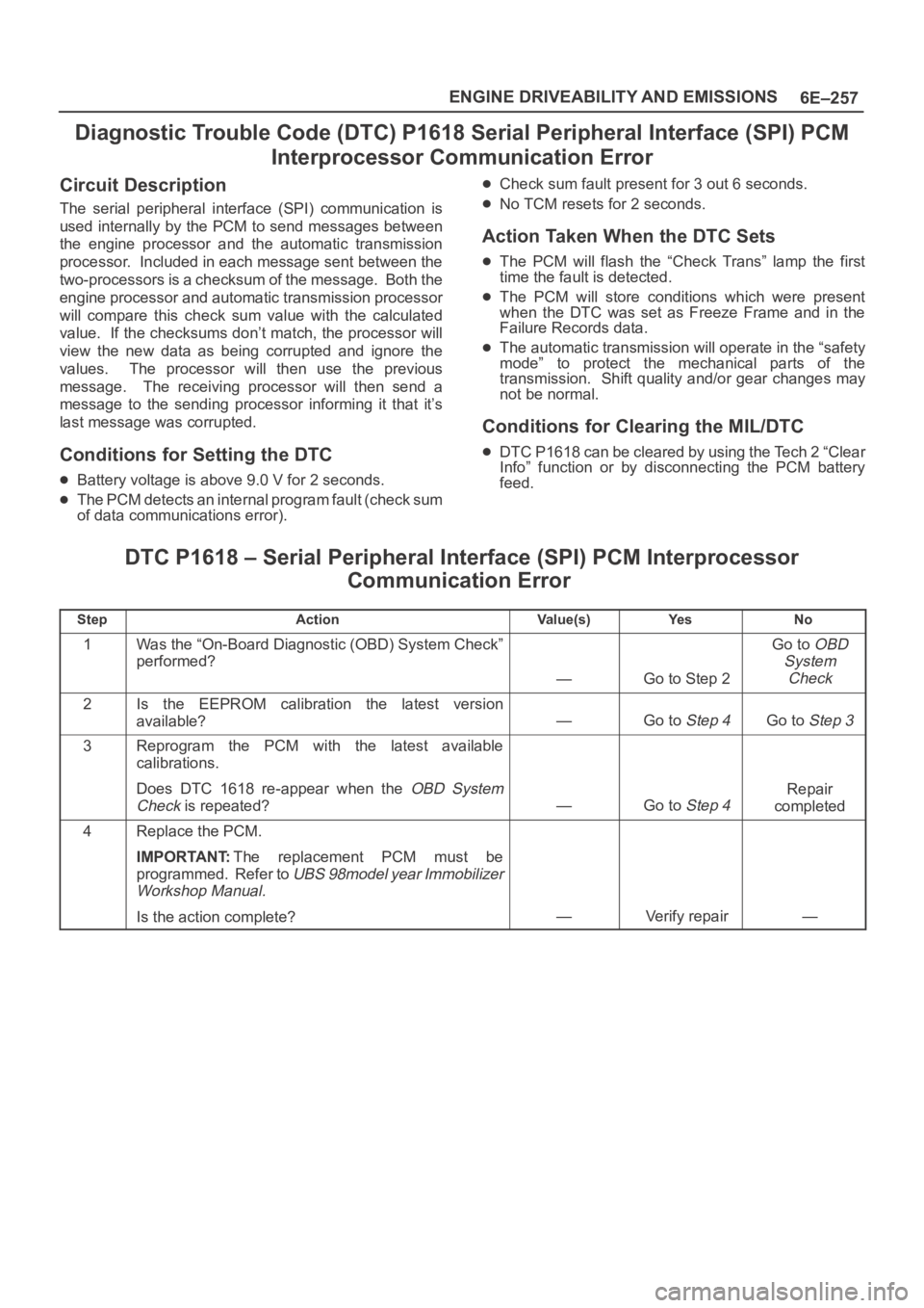
Diagnostic Trouble Code (DTC) P1618 Serial Peripheral Interface (SPI) PCM
Interprocessor Communication Error
Circuit Description
The serial peripheral interface (SPI) communication is
used internally by the PCM to send messages between
the engine processor and the automatic transmission
processor. Included in each message sent between the
two-processors is a checksum of the message. Both the
engine processor and automatic transmission processor
will compare this check sum value with the calculated
value. If the checksums don’t match, the processor will
view the new data as being corrupted and ignore the
values. The processor will then use the previous
message. The receiving processor will then send a
message to the sending processor informing it that it’s
last message was corrupted.
Conditions for Setting the DTC
Battery voltage is above 9.0 V for 2 seconds.
The PCM detects an internal program fault (check sum
of data communications error).
Check sum fault present for 3 out 6 seconds.
No TCM resets for 2 seconds.
Action Taken When the DTC Sets
The PCM will flash the “Check Trans” lamp the first
time the fault is detected.
The PCM will store conditions which were present
when the DTC was set as Freeze Frame and in the
Failure Records data.
The automatic transmission will operate in the “safety
mode” to protect the mechanical parts of the
transmission. Shift quality and/or gear changes may
not be normal.
Conditions for Clearing the MIL/DTC
DTC P1618 can be cleared by using the Tech 2 “Clear
Info” function or by disconnecting the PCM battery
feed.
DTC P1618 – Serial Peripheral Interface (SPI) PCM Interprocessor
Communication Error
StepActionVa l u e ( s )Ye sNo
1Was the “On-Board Diagnostic (OBD) System Check”
performed?
—Go to Step 2
Go to OBD
System
Check
2Is the EEPROM calibration the latest version
available?
—Go to Step 4Go to Step 3
3Reprogram the PCM with the latest available
calibrations.
Does DTC 1618 re-appear when the
OBD System
Check
is repeated?—Go to Step 4
Repair
completed
4Replace the PCM.
IMPORTANT:The replacement PCM must be
programmed. Refer to
UBS 98model year Immobilizer
Workshop Manual.
Is the action complete?—Verify repair—
Page 1375 of 6000
6E–258
ENGINE DRIVEABILITY AND EMISSIONS
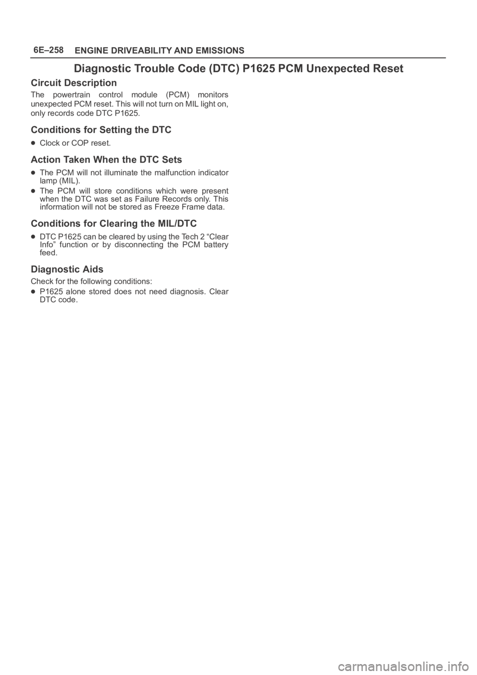
Diagnostic Trouble Code (DTC) P1625 PCM Unexpected Reset
Circuit Description
The powertrain control module (PCM) monitors
unexpected PCM reset. This will not turn on MIL light on,
only records code DTC P1625.
Conditions for Setting the DTC
Clock or COP reset.
Action Taken When the DTC Sets
The PCM will not illuminate the malfunction indicator
lamp (MIL).
The PCM will store conditions which were present
when the DTC was set as Failure Records only. This
information will not be stored as Freeze Frame data.
Conditions for Clearing the MIL/DTC
DTC P1625 can be cleared by using the Tech 2 “Clear
Info” function or by disconnecting the PCM battery
feed.
Diagnostic Aids
Check for the following conditions:
P1625 alone stored does not need diagnosis. Clear
DTC code.