1998 OPEL FRONTERA water pump
[x] Cancel search: water pumpPage 960 of 6000
6A–4
ENGINE MECHANICAL
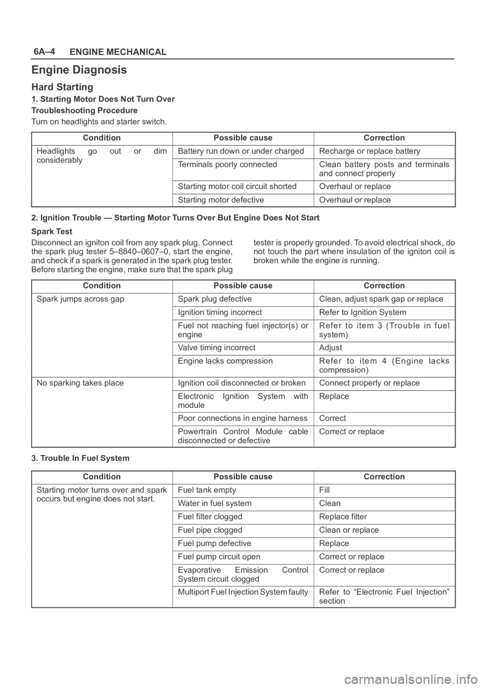
Engine Diagnosis
Hard Starting
1. Starting Motor Does Not Turn Over
Troubleshooting Procedure
Turn on headlights and starter switch.
Condition
Possible causeCorrection
Headlights go out or dim
considerably
Battery run down or under chargedRecharge or replace battery
considerablyTerminals poorly connectedClean battery posts and terminals
and connect properly
Starting motor coil circuit shortedOverhaul or replace
Starting motor defectiveOverhaul or replace
2. Ignition Trouble — Starting Motor Turns Over But Engine Does Not Start
Spark Test
Disconnect an igniton coil from any spark plug. Connect
the spark plug tester 5–8840–0607–0, start the engine,
a n d c h e c k i f a s p a r k i s g e n e r a t e d in t h e s p a r k p l u g t e s t e r.
Before starting the engine, make sure that the spark plugtester is properly grounded. To avoid electrical shock, do
not touch the part where insulation of the igniton coil is
broken while the engine is running.
Condition
Possible causeCorrection
Spark jumps across gapSpark plug defectiveClean, adjust spark gap or replace
Ignition timing incorrectRefer to Ignition System
Fuel not reaching fuel injector(s) or
engineRefer to item 3 (Trouble in fuel
system)
Valve timing incorrectAdjust
Engine lacks compressionRefer to item 4 (Engine lacks
compression)
No sparking takes placeIgnition coil disconnected or brokenConnect properly or replace
Electronic Ignition System with
moduleReplace
Poor connections in engine harnessCorrect
Powertrain Control Module cable
disconnected or defectiveCorrect or replace
3. Trouble In Fuel System
Condition
Possible causeCorrection
Starting motor turns over and spark
occurs but engine does not start
Fuel tank emptyFill
occurs but engine does not start.Water in fuel systemClean
Fuel filter cloggedReplace filter
Fuel pipe cloggedClean or replace
Fuel pump defectiveReplace
Fuel pump circuit openCorrect or replace
Evaporative Emission Control
System circuit cloggedCorrect or replace
Multiport Fuel Injection System faultyRefer to “Electronic Fuel Injection”
section
Page 966 of 6000

6A–10
ENGINE MECHANICAL
Engine Lacks Power
ConditionPossible causeCorrection
Trouble in fuel systemFuel Pressure Control Valve not
working normallyReplace
Fuel injector cloggedClean or replace
Fuel pipe cloggedClean
Fuel filter clogged or fouledReplace
Fuel pump drive circuit not working
normallyCorrect or replace
Fuel tank not sufficiently breathing
due to clogged Evaporative
Emission Control System circuitClean or replace
Water in fuel systemClean
Inferior quality fuel in fuel systemUse fuel of specified octane rating
Powertrain Control Module supplied
poor voltageCorrect circuit
Throttle Position Sensor cable
broken or poor connectionsCorrect or replace
Throttle Position Sensor defectiveReplace
Mass Airflow Sensor not working
normallyReplace
Manifold Absolute Pressure Sensor
not working normallyReplace
Intake Air Temperature Sensor not
working normallyReplace
Engine Coolant Temperature Sensor
circuit open or shortedCorrect or replace
Engine Coolant Temperature Sensor
defectiveReplace
Powertrain Control Module defectiveReplace
Trouble in intake or exhaust systemAir Cleaner Filter cloggedReplace filter element
Air duct kinked or flattenedCorrect or replace
Ignition failure————Refer to Hard Start Troubleshooting
Guide
Heat range of spark plug inadequateInstall spark plugs of adequate heat
range
Ignition coil defectiveReplace
Page 969 of 6000
6A–13
ENGINE MECHANICAL
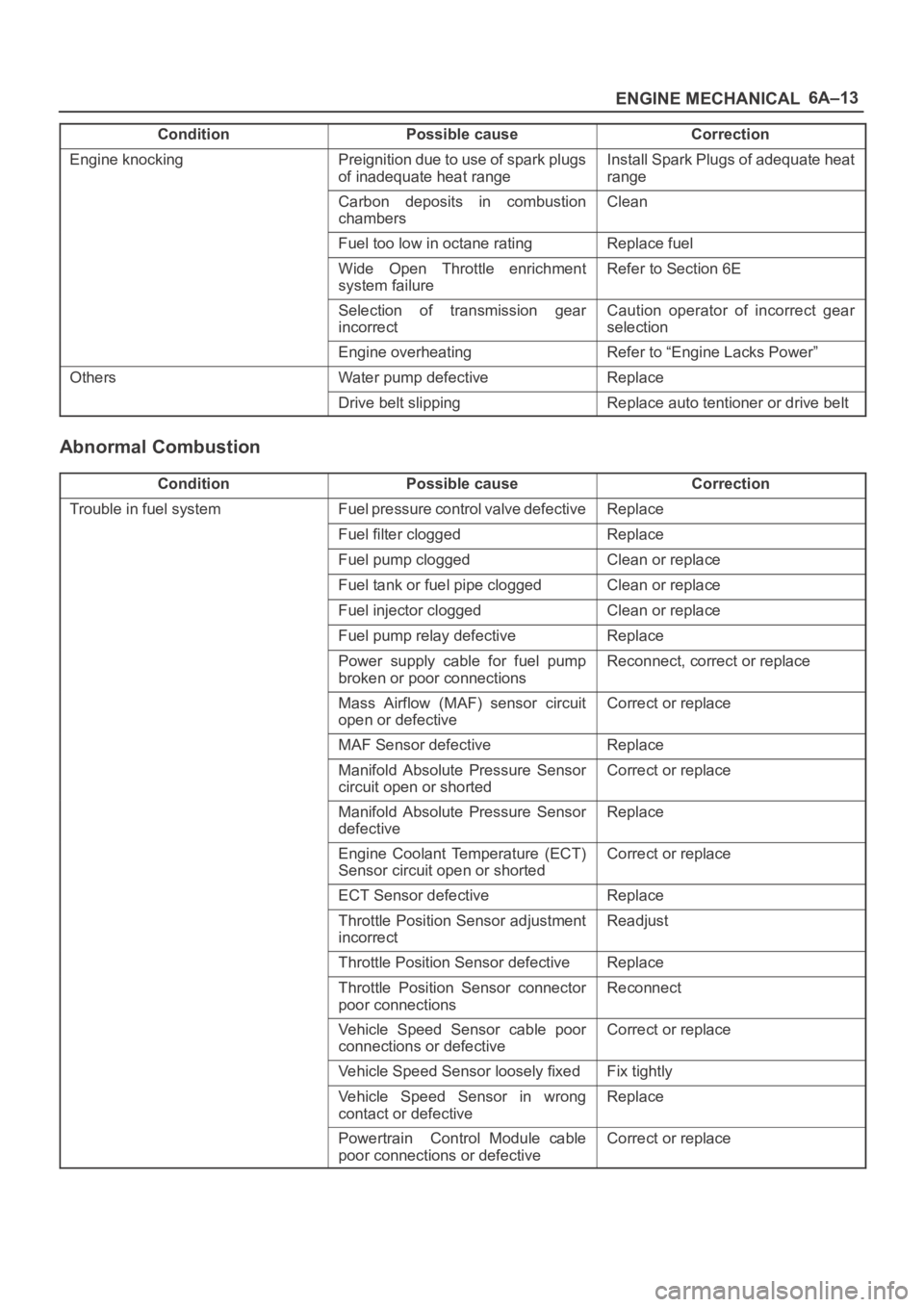
Condition CorrectionPossible cause
Engine knockingPreignition due to use of spark plugs
of inadequate heat rangeInstall Spark Plugs of adequate heat
range
Carbon deposits in combustion
chambersClean
Fuel too low in octane ratingReplace fuel
Wide Open Throttle enrichment
system failureRefer to Section 6E
Selection of transmission gear
incorrectCaution operator of incorrect gear
selection
Engine overheatingRefer to “Engine Lacks Power”
OthersWater pump defectiveReplace
Drive belt slippingReplace auto tentioner or drive belt
Abnormal Combustion
ConditionPossible causeCorrection
Trouble in fuel systemFuel pressure control valve defectiveReplace
Fuel filter cloggedReplace
Fuel pump cloggedClean or replace
Fuel tank or fuel pipe cloggedClean or replace
Fuel injector cloggedClean or replace
Fuel pump relay defectiveReplace
Power supply cable for fuel pump
broken or poor connectionsReconnect, correct or replace
Mass Airflow (MAF) sensor circuit
open or defectiveCorrect or replace
MAF Sensor defectiveReplace
Manifold Absolute Pressure Sensor
circuit open or shortedCorrect or replace
Manifold Absolute Pressure Sensor
defectiveReplace
Engine Coolant Temperature (ECT)
Sensor circuit open or shortedCorrect or replace
ECT Sensor defectiveReplace
Throttle Position Sensor adjustment
incorrectReadjust
Throttle Position Sensor defectiveReplace
Throttle Position Sensor connector
poor connectionsReconnect
Vehicle Speed Sensor cable poor
connections or defectiveCorrect or replace
Vehicle Speed Sensor loosely fixedFix tightly
Vehicle Speed Sensor in wrong
contact or defectiveReplace
Powertrain Control Module cable
poor connections or defectiveCorrect or replace
Page 972 of 6000

6A–16
ENGINE MECHANICAL
Lubrication Problems
ConditionPossible causeCorrection
Oil pressure too lowWrong oil in useReplace with correct engine oil
Relief valve stickingReplace
Oil pump not operating properlyCorrect or replace
Oil pump strainer cloggedClean or replace strainer
Oil pump wornReplace
Oil pressure gauge defectiveCorrect or replace
Crankshaft bearing or connecting
rod bearing wornReplace
Oil contaminationWrong oil in useReplace with correct engine oil
Oil filter cloggedReplace oil filter
Cylinder head gasket damageReplace gasket
Burned gases leakingReplace piston and piston rings or
cylinder body assembly
Oil not reaching valve systemOil passage in cylinder head or
cylinder body cloggedClean or correct
Engine Oil Pressure Check
1. Check for dirt, gasoline or water in the engine oil.
a. Check the viscosity of the oil.
b. Change the oil if the viscosity is outside the
specified standard.
c. Refer to the “Maintenance and Lubrication” section
of this manual.
2. Check the engine oil level.
The level should fall somewhere between the “ADD”
and the “FULL” marks on the oil level dipstick.
If the oil level does not reach the “ADD” mark on the
oil level dipstick, engine oil must be added.3. Remove the oil pressure unit.
4. Install an oil pressure gauge.
5. Start the engine and allow the engine to reach normal
operating temperature (About 80
C).
6. Measure the oil pressure.
Oil pressure should be:
392–550 kPa (56.9–80.4 psi) at 3000 rpm.
7. Stop the engine.
8. Remove the oil pressure gauge.
9. Install the oil pressure unit.
10. Start the engine and check for leaks.
Page 986 of 6000

6A–30
ENGINE MECHANICAL
Installation
NOTE: For correct belt installation, the letter on the belt
must be able to be read as viewed from the front of the
vehicle.
014RY00042
Legend
(1) Crankshaft Timing Pulley
(2) RH Bank Camshaft Drive Gear Pulley
(3) Water Pump Pulley
(4) Idle Pulley
(5) LH Bank Camshaft Drive Gear Pulley
(6) Tension Pulley
014RY00043
Legend
(7) Alignment Mark on Oil Pump.
(8) Alignment Mark on Timing Belt
(9) Alignment Mark (notch) on Crankshaft Timing
Pulley.
(10) Alignment Mark (groove) on Crankshaft Timing
Pulley.
014RW006
Legend
(1) Timing Belt
(2) Engine Rotation Direction
(3) Cylinder Head Side
1. Install timing belt.
1. Align the mark (notch) of crankshaft timing pulley
(2) with mark on oil pump (1).
Align the mark (groove) on the crankshaft timing
pulley (3) with alignment mark (white dots line) on
the timing belt (4).
NOTE: When timing marks are aligned, No.2 piston will
be on Top Dead Center.
014RW003
Legend
(1) Alignment Mark on Oil Pump
(2) Groove on Crankshaft Timing Pulley
(3) Alignment Mark on Crankshaft Timing Pulley
(4) Alignment Mark on Timing Belt
Page 1049 of 6000
6A–93
ENGINE MECHANICAL
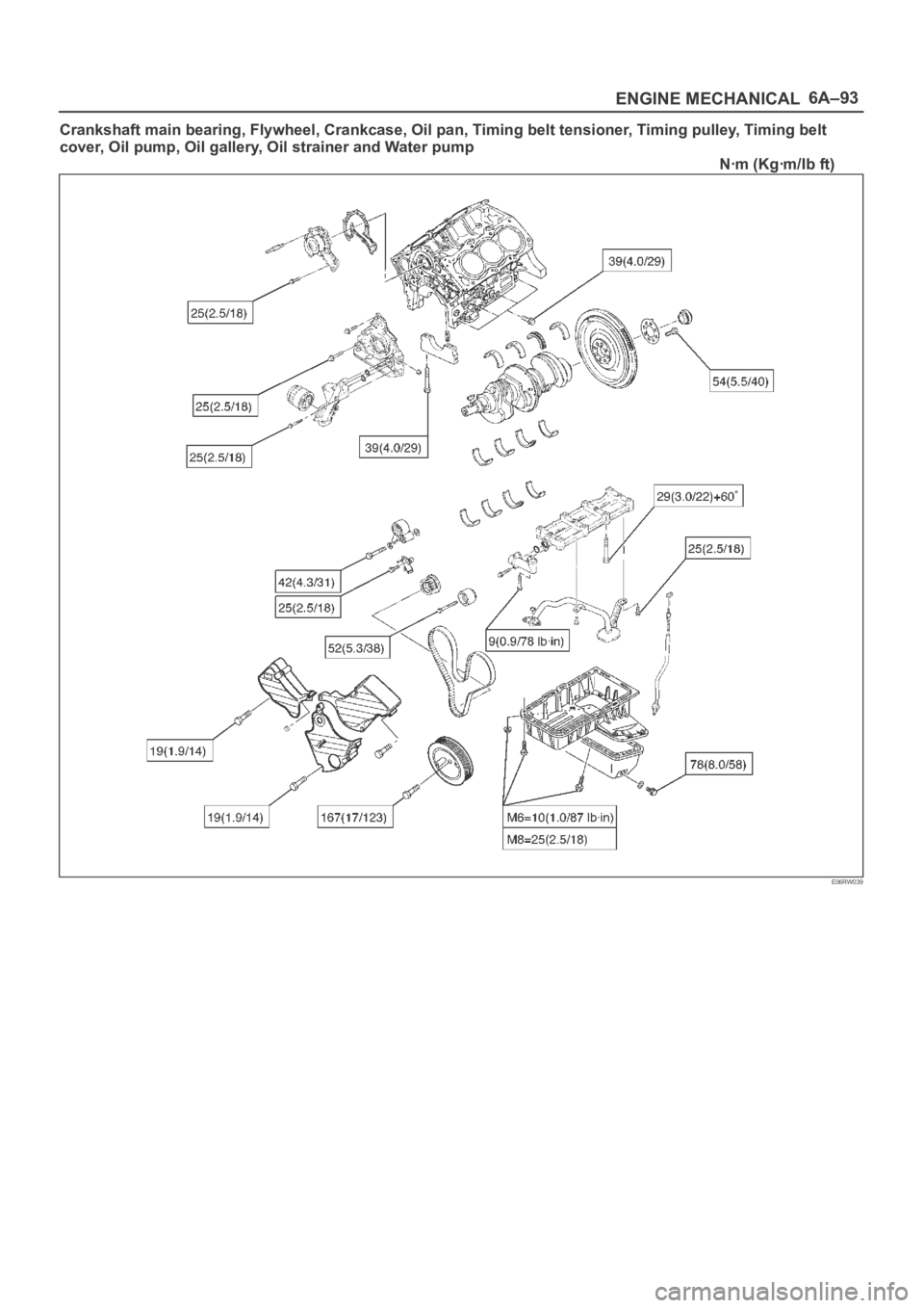
Crankshaft main bearing, Flywheel, Crankcase, Oil pan, Timing belt tensioner, Timing pulley, Timing belt
cover, Oil pump, Oil gallery, Oil strainer and Water pump
Nꞏm (Kgꞏm/Ib ft)
E06RW039
Page 1050 of 6000
6A–94
ENGINE MECHANICAL
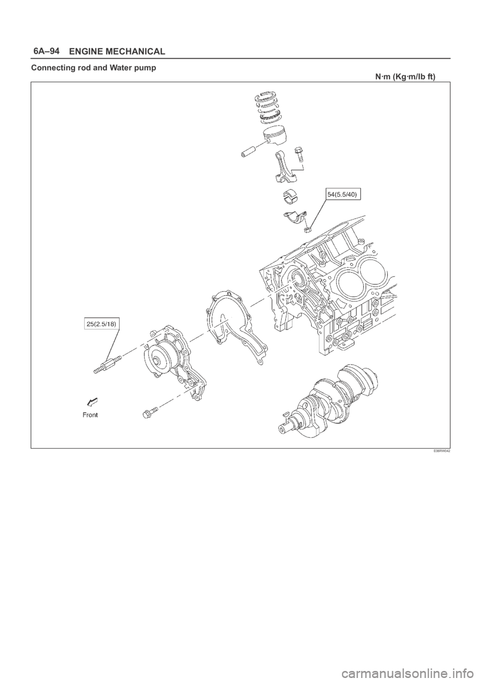
Connecting rod and Water pump
Nꞏm (Kgꞏm/Ib ft)
E06RW042
Page 1054 of 6000
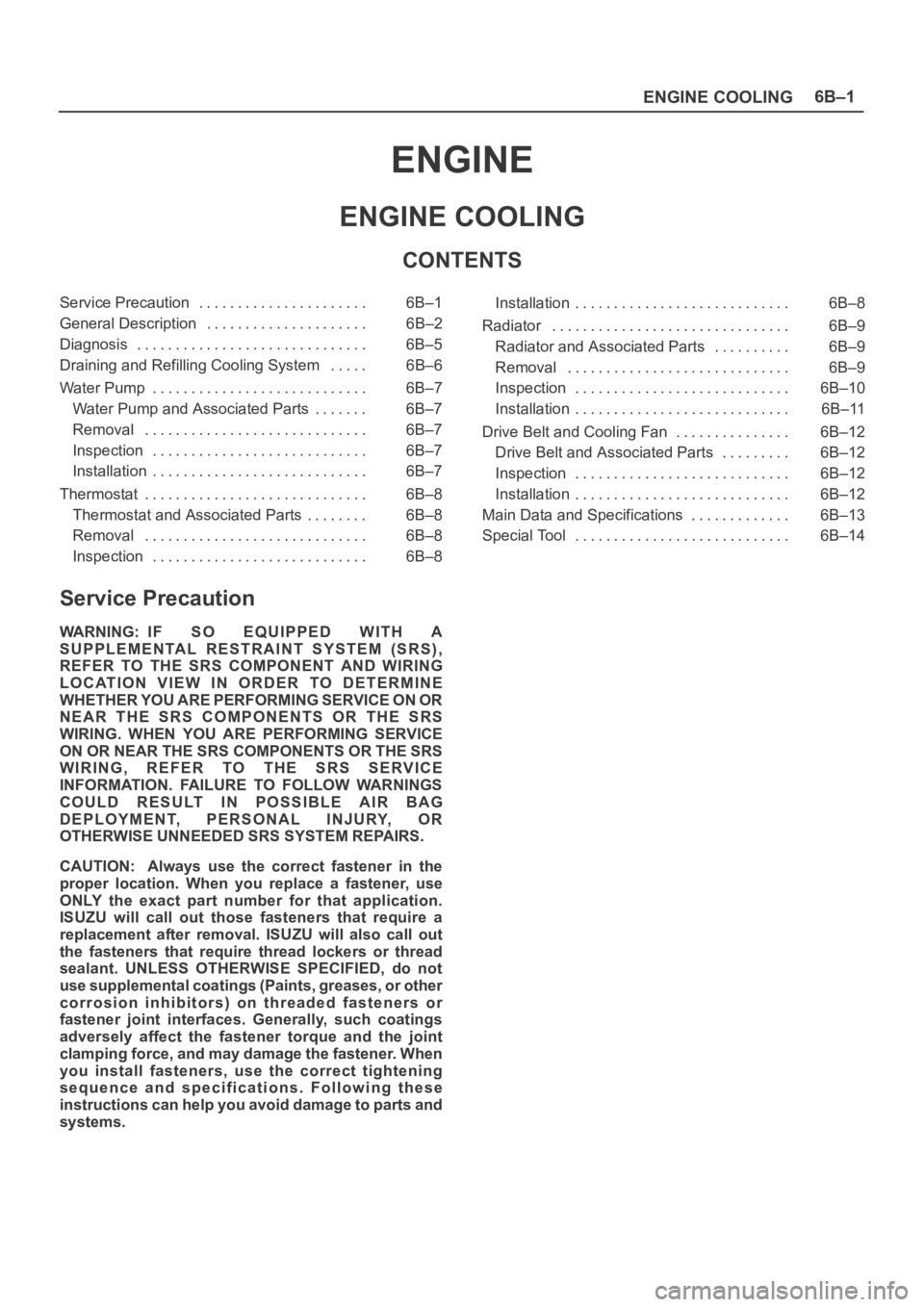
ENGINE COOLING6B–1
ENGINE
ENGINE COOLING
CONTENTS
Service Precaution 6B–1. . . . . . . . . . . . . . . . . . . . . .
General Description 6B–2. . . . . . . . . . . . . . . . . . . . .
Diagnosis 6B–5. . . . . . . . . . . . . . . . . . . . . . . . . . . . . .
Draining and Refilling Cooling System 6B–6. . . . .
Water Pump 6B–7. . . . . . . . . . . . . . . . . . . . . . . . . . . .
Water Pump and Associated Parts 6B–7. . . . . . .
Removal 6B–7. . . . . . . . . . . . . . . . . . . . . . . . . . . . .
Inspection 6B–7. . . . . . . . . . . . . . . . . . . . . . . . . . . .
Installation 6B–7. . . . . . . . . . . . . . . . . . . . . . . . . . . .
Thermostat 6B–8. . . . . . . . . . . . . . . . . . . . . . . . . . . . .
Thermostat and Associated Parts 6B–8. . . . . . . .
Removal 6B–8. . . . . . . . . . . . . . . . . . . . . . . . . . . . .
Inspection 6B–8. . . . . . . . . . . . . . . . . . . . . . . . . . . . Installation 6B–8. . . . . . . . . . . . . . . . . . . . . . . . . . . .
Radiator 6B–9. . . . . . . . . . . . . . . . . . . . . . . . . . . . . . .
Radiator and Associated Parts 6B–9. . . . . . . . . .
Removal 6B–9. . . . . . . . . . . . . . . . . . . . . . . . . . . . .
Inspection 6B–10. . . . . . . . . . . . . . . . . . . . . . . . . . . .
Installation 6B–11. . . . . . . . . . . . . . . . . . . . . . . . . . . .
Drive Belt and Cooling Fan 6B–12. . . . . . . . . . . . . . .
Drive Belt and Associated Parts 6B–12. . . . . . . . .
Inspection 6B–12. . . . . . . . . . . . . . . . . . . . . . . . . . . .
Installation 6B–12. . . . . . . . . . . . . . . . . . . . . . . . . . . .
Main Data and Specifications 6B–13. . . . . . . . . . . . .
Special Tool 6B–14. . . . . . . . . . . . . . . . . . . . . . . . . . . .
Service Precaution
WARNING: IF SO EQUIPPED WITH A
SUPPLEMENTAL RESTRAINT SYSTEM (SRS),
REFER TO THE SRS COMPONENT AND WIRING
LOCATION VIEW IN ORDER TO DETERMINE
WHETHER YOU ARE PERFORMING SERVICE ON OR
NEAR THE SRS COMPONENTS OR THE SRS
WIRING. WHEN YOU ARE PERFORMING SERVICE
ON OR NEAR THE SRS COMPONENTS OR THE SRS
WIRING, REFER TO THE SRS SERVICE
INFORMATION. FAILURE TO FOLLOW WARNINGS
COULD RESULT IN POSSIBLE AIR BAG
DEPLOYMENT, PERSONAL INJURY, OR
OTHERWISE UNNEEDED SRS SYSTEM REPAIRS.
CAUTION: Always use the correct fastener in the
proper location. When you replace a fastener, use
ONLY the exact part number for that application.
ISUZU will call out those fasteners that require a
replacement after removal. ISUZU will also call out
the fasteners that require thread lockers or thread
sealant. UNLESS OTHERWISE SPECIFIED, do not
use supplemental coatings (Paints, greases, or other
corrosion inhibitors) on threaded fasteners or
fastener joint interfaces. Generally, such coatings
adversely affect the fastener torque and the joint
clamping force, and may damage the fastener. When
you install fasteners, use the correct tightening
sequence and specifications. Following these
instructions can help you avoid damage to parts and
systems.