1998 OPEL FRONTERA recommended oil
[x] Cancel search: recommended oilPage 497 of 6000

4A2A–30
DIFFERENTIAL (REAR 220mm)
3. After measuring dimensions of each of the above
sections, proceed with the adjustment in the following
manner:
Adjust the clearance to satisfy the equation below.
{(F – B) + G – H}=0.05 – 0.20 mm
Also, select the thrust washers so that the
dimensional difference between the back surfaces of
the left and right pressure rings to the thrust washers
is 0.05mm or less.
Thickness : 1.5mm (0.059 in)
1.6 mm(0.063 in)
1.7 mm(0.067 in)
NOTE: When assembling the parts, apply recommended
gear oil sufficiently to each of the parts, especially, to the
contact surfaces and sliding surfaces.
1. Install Differential cage B.
2. Install Thrust washer.
3. Install Spring disc.
When assembling the spring disc, make sure the
mounting direction is correct as shown in figure.
425RS068
Legend
(1) Friction Plate
(2) Spring Disc
(3) Friction Disc
4. Inatall Spring disc.
5. Inatall Friction plate.
6. Inatall Friction disc.
7. Inatall Friction plate.
8. Inatall Friction disc.
9. Inatall Pressure ring.
10. Inatall Side gear.
11. Inatall Pinion and pinion shaft.
12. Inatall Side gear.
13. Inatall Pressure ring.
14. Inatall Friction disc.15. Inatall Friction plate.
16. Inatall Friction disc.
17. Inatall Friction plate.
18. Inatall Spring disc.
When assembling the spring disc, make sure the
mounting direction is correct.
19. Inatall Spring disc.
20. Inatall Thrust washer.
21. Inatall Differential cage A.
22. Inatall Screw.
Matching the guide marks of the differential cages A
and B, tighten the screws evenly in the diagonal
order.
425RS055
Page 729 of 6000

4D1–8
TRANSFER CASE (STANDARD TYPE)
Transfer Rear Oil Seal
Removal
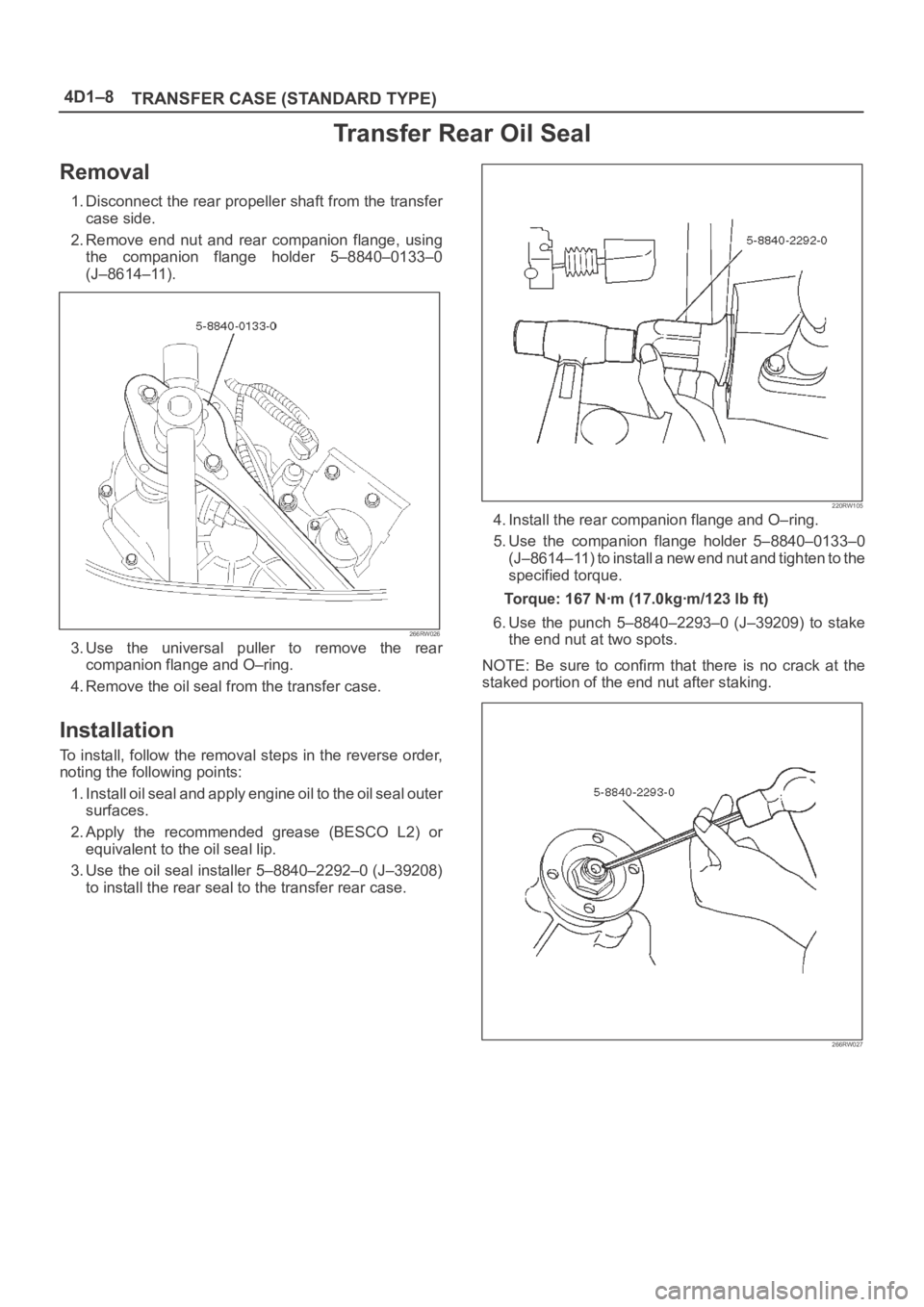
1. Disconnect the rear propeller shaft from the transfer
case side.
2. Remove end nut and rear companion flange, using
the companion flange holder 5–8840–0133–0
(J–8614–11).
266RW026
3. Use the universal puller to remove the rear
companion flange and O–ring.
4. Remove the oil seal from the transfer case.
Installation
To install, follow the removal steps in the reverse order,
noting the following points:
1. Install oil seal and apply engine oil to the oil seal outer
surfaces.
2. Apply the recommended grease (BESCO L2) or
equivalent to the oil seal lip.
3. Use the oil seal installer 5–8840–2292–0 (J–39208)
to install the rear seal to the transfer rear case.
220RW105
4. Install the rear companion flange and O–ring.
5. Use the companion flange holder 5–8840–0133–0
(J–8614–11) to install a new end nut and tighten to the
specified torque.
Torque: 167 Nꞏm (17.0kgꞏm/123 lb ft)
6. Use the punch 5–8840–2293–0 (J–39209) to stake
the end nut at two spots.
NOTE: Be sure to confirm that there is no crack at the
staked portion of the end nut after staking.
266RW027
Page 738 of 6000

TRANSFER CASE (STANDARD TYPE)
4D1–17
2. Remove the rear output shaft assembly (1) from the
transfer rear cover (with oil seal).
3. Remove ball bearing (8), using a bench press and the
bearing remover 5–8840–0015–0 (J–22912–01) .
226RW186
4. Remove the speedometer drive gear (7).
5. Remove the ball (6).
6. Remove the bearing snap ring (5), using a pair of snap
ring pliers.
7. Remove the ball bearing (4) from the rear output
shaft, using a bench press and the bearing remover
5–8840–0015–0 (J–22912–01).
226RW187
Inspection and Repair
Refer to “TRANSFER CASE ASSEMBLY” in this section
for inspection and repair.
Reassembly
1. Install transfer rear cover (with oil seal).
Oil seal replacement
Remove the oil seal from the transfer rear cover.
Apply engine oil to the oil seal outer surfaces.
Fill in recommended grease (BESCO L2) or
equivalent in the oil seal lip.
Use the oil seal installer 5–8840–2292–0 (J–39208)
to install the rear oil seal to the transfer rear cover.
220RW104
2. Set the snap ring (3), and install ball bearing (4) to the
rear output shaft (2), using the ball bearing installer
5–8840–2159–0 (J–37223) and the adapter
5–8840–2192–1 (J–37486–A).
262RW068
Page 745 of 6000

4D1–24
TRANSFER CASE (STANDARD TYPE)
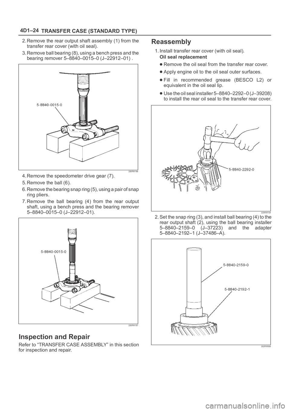
2. Remove the rear output shaft assembly (1) from the
transfer rear cover (with oil seal).
3. Remove ball bearing (8), using a bench press and the
bearing remover 5–8840–0015–0 (J–22912–01) .
226RW186
4. Remove the speedometer drive gear (7).
5. Remove the ball (6).
6. Remove the bearing snap ring (5), using a pair of snap
ring pliers.
7. Remove the ball bearing (4) from the rear output
shaft, using a bench press and the bearing remover
5–8840–0015–0 (J–22912–01).
226RW187
Inspection and Repair
Refer to “TRANSFER CASE ASSEMBLY” in this section
for inspection and repair.
Reassembly
1. Install transfer rear cover (with oil seal).
Oil seal replacement
Remove the oil seal from the transfer rear cover.
Apply engine oil to the oil seal outer surfaces.
Fill in recommended grease (BESCO L2) or
equivalent in the oil seal lip.
Use the oil seal installer 5–8840–2292–0 (J–39208)
to install the rear oil seal to the transfer rear cover.
220RW104
2. Set the snap ring (3), and install ball bearing (4) to the
rear output shaft (2), using the ball bearing installer
5–8840–2159–0 (J–37223) and the adapter
5–8840–2192–1 (J–37486–A).
262RW068
Page 758 of 6000

TRANSFER CASE (STANDARD TYPE)
4D1–37
Reassembly
1. Put the transfer case (with oil seal) as the following
illustration.
Input shaft oil seal (1) replacement
1. Remove the oil seal from the transfer case.
2. Apply engine oil to the oil seal outer surfaces.
3. Apply recommended grease (BESCO L2) or
equivalent to the oil seal lip.
4. Use the oil seal installer 5–8840–2279–0
(J–38592) to install the oil seal to the transfer
case.
220RW106
Front output shaft oil seal (2) replacement
1. Remove the oil seal from the transfer case.
2. Apply engine oil to the oil seal outer surfaces.
3. Apply recommended grease (BESCO L2) or
equivalent to the oil seal lip.
4. Use the oil seal installer 5–8840–2281–0
(J–38594) to install the oil seal to the transfer
case.
220RW107
Legend
(2) Front output shaft oil seal
2. Apply chassis grease (3) to the sub–gear (23) and the
counter gear (22) thrust surfaces.
226RW134
Page 967 of 6000

6A–11
ENGINE MECHANICAL
Condition CorrectionPossible cause
Engine overheatingLevel of Engine Coolant too lowReplenish
Fan clutch defectiveReplace
Incorrect fan installedReplace
Thermostat defectiveReplace
Engine Coolant pump defectiveCorrect or replace
Radiator cloggedClean or replace
Radiator filler cap defectiveReplace
Level of oil in engine crankcase too
low or wrong engine oilChange or replenish
Resistance in exhaust system
increasedClean exhaust system or replace
defective parts
Throttle Position Sensor adjustment
incorrectReplace with Throttle Valve ASM
Throttle Position Sensor circuit open
or shortedCorrect or replace
Cylinder head gasket damagedReplace
Engine overcoolingThermostat defectiveReplace (Use a thermostat set to
open at 82
C (180F))
Engine lacks compression————Refer to Hard Start
OthersTire inflation pressure abnormalAdjust to recommended pressures
Brake dragAdjust
Clutch slippingAdjust or replace
Level of oil in engine crankcase too
highCorrect level of engine oil
Exhaust Gas Recirculation Valve
defectiveReplace
Engine Noisy
Abnormal engine noise often consists of various noises
originating in rotating parts, sliding parts and othermoving parts of the engine. It is, therefore, advisable to
locate the source of noise systematically.
Condition
Possible causeCorrection
Noise from crank journals or from
crank bearings
(Faulty crank journals and crankOil clearance increased due to worn
crank journals or crank bearingsReplace crank bearings and
crankshaft or regrind crankshaft and
install the undersize bearing
yj
bearings usually make dull noise that
becomes more evident when
accelerating)Crankshaft out of roundReplace crank bearings and
crankshaft or regrind crankshaft and
install the undersize bearing
Crank bearing seizedCrank bearing seized. Replace crank
bearings and crankshaft or regrind
crankshaft and install the undersize
bearing
Troubleshooting Procedure
Short out each spark plug in sequence using insulated
spark plug wire removers. Locate cylinder with defectivebearing by listening for abnormal noise that stops when
spark plug is shorted out.
Page 971 of 6000

6A–15
ENGINE MECHANICAL
Condition CorrectionPossible cause
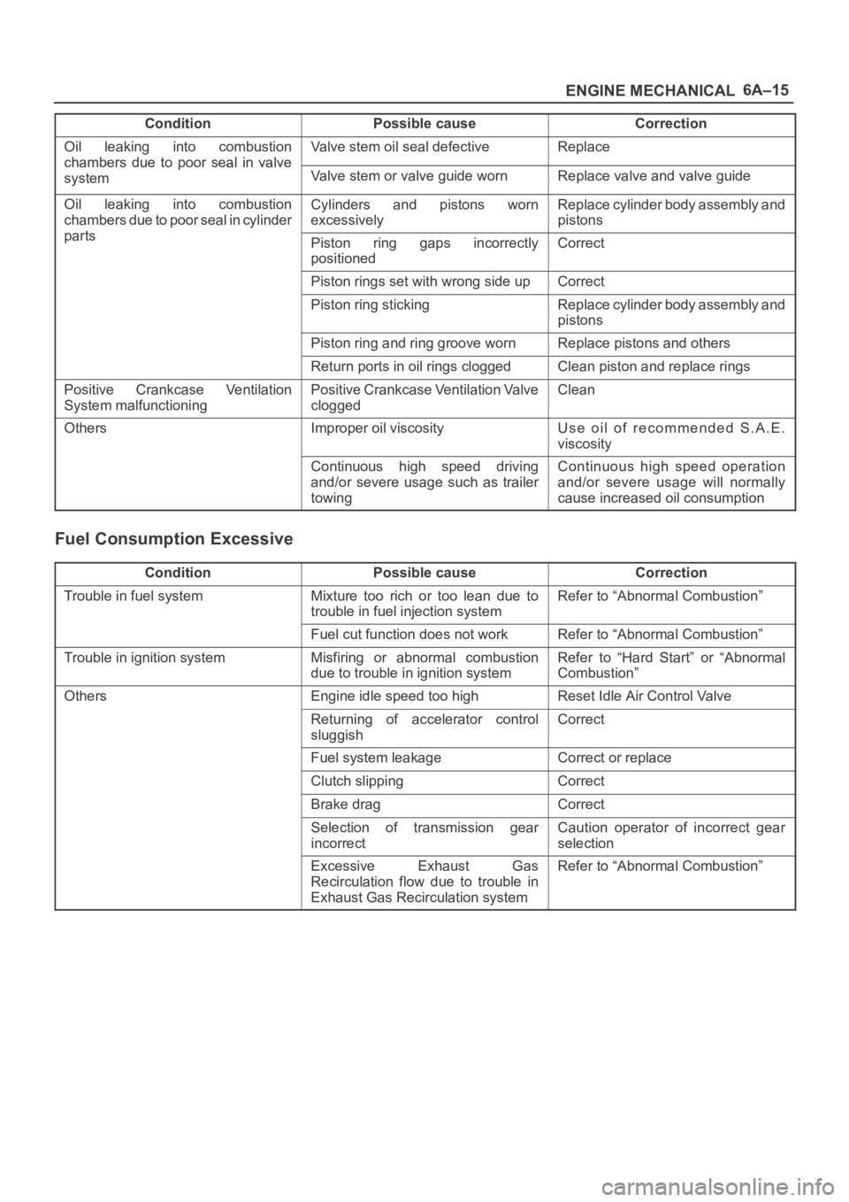
Oil leaking into combustion
chambers due topoor seal in valve
Valve stem oil seal defectiveReplace
chambers due to oor seal in valve
systemValve stem or valve guide wornReplace valve and valve guide
Oil leaking into combustion
chambers due to poor seal in cylinder
t
Cylinders and pistons worn
excessivelyReplace cylinder body assembly and
pistons
partsPiston ring gaps incorrectly
positionedCorrect
Piston rings set with wrong side upCorrect
Piston ring stickingReplace cylinder body assembly and
pistons
Piston ring and ring groove wornReplace pistons and others
Return ports in oil rings cloggedClean piston and replace rings
Positive Crankcase Ventilation
System malfunctioningPositive Crankcase Ventilation Valve
cloggedClean
OthersImproper oil viscosityUse oil of recommended S.A.E.
viscosity
Continuous high speed driving
and/or severe usage such as trailer
towingContinuous high speed operation
and/or severe usage will normally
cause increased oil consumption
Fuel Consumption Excessive
ConditionPossible causeCorrection
Trouble in fuel systemMixture too rich or too lean due to
trouble in fuel injection systemRefer to “Abnormal Combustion”
Fuel cut function does not workRefer to “Abnormal Combustion”
Trouble in ignition systemMisfiring or abnormal combustion
due to trouble in ignition systemRefer to “Hard Start” or “Abnormal
Combustion”
OthersEngine idle speed too highReset Idle Air Control Valve
Returning of accelerator control
sluggishCorrect
Fuel system leakageCorrect or replace
Clutch slippingCorrect
Brake dragCorrect
Selection of transmission gear
incorrectCaution operator of incorrect gear
selection
Excessive Exhaust Gas
Recirculation flow due to trouble in
Exhaust Gas Recirculation systemRefer to “Abnormal Combustion”
Page 1056 of 6000

ENGINE COOLING6B–3
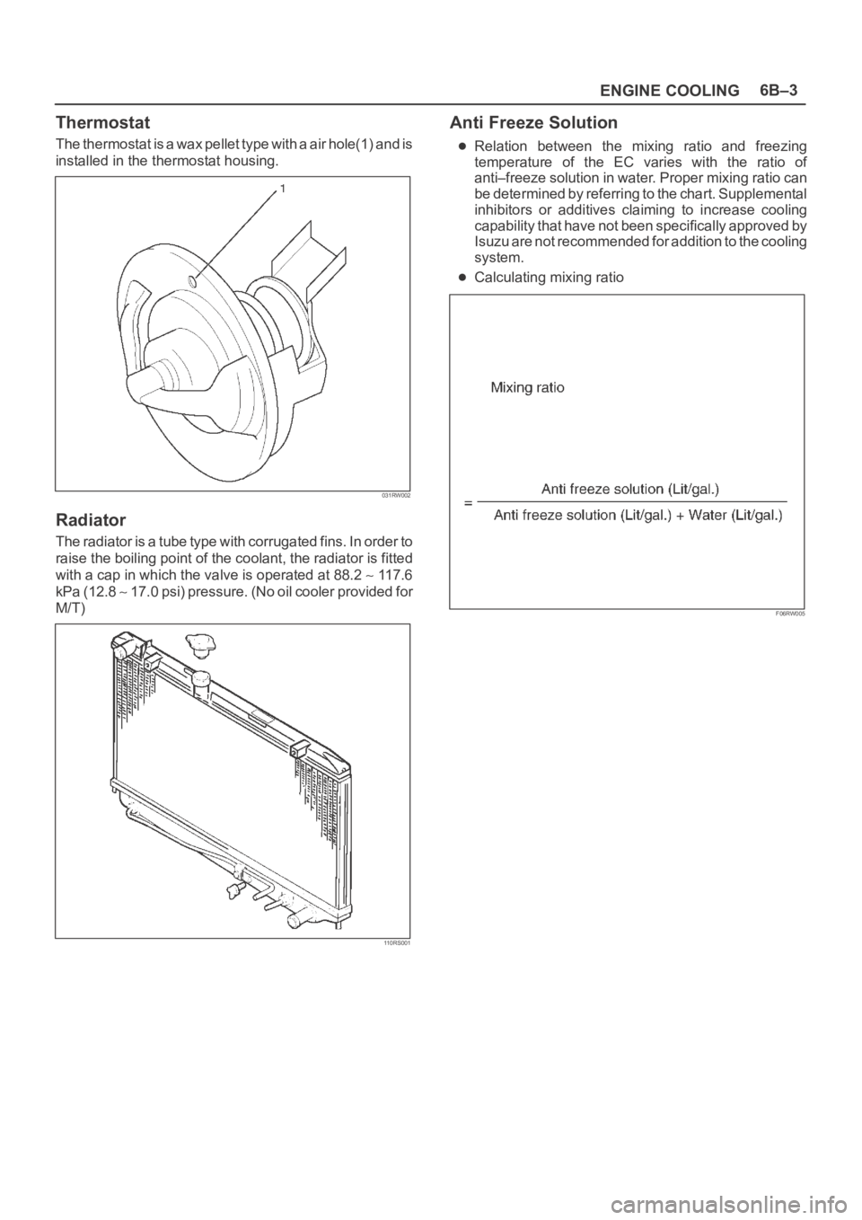
Thermostat
The thermostat is a wax pellet type with a air hole(1) and is
installed in the thermostat housing.
031RW002
Radiator
The radiator is a tube type with corrugated fins. In order to
raise the boiling point of the coolant, the radiator is fitted
with a cap in which the valve is operated at 88.2
117.6
kPa (12.8
1 7 . 0 p s i ) p r e s s u r e . ( N o o i l c o o l e r p r o v i d e d f o r
M/T)
110RS001
Anti Freeze Solution
Relation between the mixing ratio and freezing
temperature of the EC varies with the ratio of
anti–freeze solution in water. Proper mixing ratio can
be determined by referring to the chart. Supplemental
inhibitors or additives claiming to increase cooling
capability that have not been specifically approved by
Isuzu are not recommended for addition to the cooling
system.
Calculating mixing ratio
F06RW005