1998 OPEL FRONTERA oil filter
[x] Cancel search: oil filterPage 959 of 6000

6A–3
ENGINE MECHANICAL
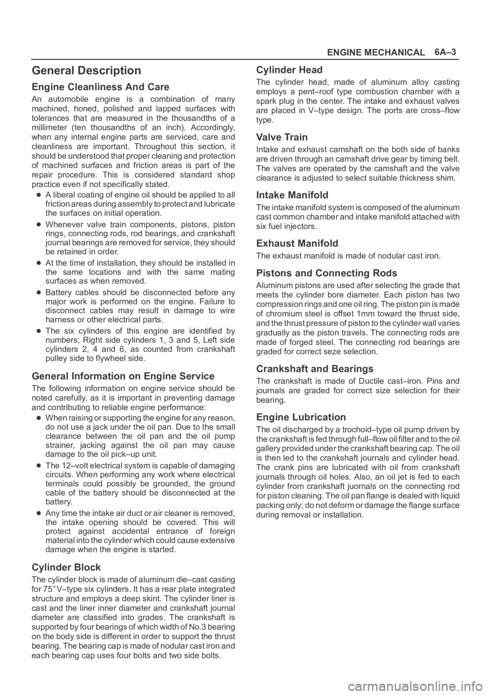
General Description
Engine Cleanliness And Care
An automobile engine is a combination of many
machined, honed, polished and lapped surfaces with
tolerances that are measured in the thousandths of a
millimeter (ten thousandths of an inch). Accordingly,
when any internal engine parts are serviced, care and
cleanliness are important. Throughout this section, it
should be understood that proper cleaning and protection
of machined surfaces and friction areas is part of the
repair procedure. This is considered standard shop
practice even if not specifically stated.
A liberal coating of engine oil should be applied to all
friction areas during assembly to protect and lubricate
the surfaces on initial operation.
Whenever valve train components, pistons, piston
rings, connecting rods, rod bearings, and crankshaft
journal bearings are removed for service, they should
be retained in order.
At the time of installation, they should be installed in
the same locations and with the same mating
surfaces as when removed.
Battery cables should be disconnected before any
major work is performed on the engine. Failure to
disconnect cables may result in damage to wire
harness or other electrical parts.
The six cylinders of this engine are identified by
numbers; Right side cylinders 1, 3 and 5, Left side
cylinders 2, 4 and 6, as counted from crankshaft
pulley side to flywheel side.
General Information on Engine Service
The following information on engine service should be
noted carefully, as it is important in preventing damage
and contributing to reliable engine performance:
When raising or supporting the engine for any reason,
do not use a jack under the oil pan. Due to the small
clearance between the oil pan and the oil pump
strainer, jacking against the oil pan may cause
damage to the oil pick–up unit.
The 12–volt electrical system is capable of damaging
circuits. When performing any work where electrical
terminals could possibly be grounded, the ground
cable of the battery should be disconnected at the
battery.
Any time the intake air duct or air cleaner is removed,
the intake opening should be covered. This will
protect against accidental entrance of foreign
material into the cylinder which could cause extensive
damage when the engine is started.
Cylinder Block
The cylinder block is made of aluminum die–cast casting
for 75
V–type six cylinders. It has a rear plate integrated
structure and employs a deep skint. The cylinder liner is
cast and the liner inner diameter and crankshaft journal
diameter are classified into grades. The crankshaft is
supported by four bearings of which width of No.3 bearing
on the body side is different in order to support the thrust
bearing. The bearing cap is made of nodular cast iron and
each bearing cap uses four bolts and two side bolts.
Cylinder Head
The cylinder head, made of aluminum alloy casting
employs a pent–roof type combustion chamber with a
spark plug in the center. The intake and exhaust valves
are placed in V–type design. The ports are cross–flow
type.
Va l v e Tr a i n
Intake and exhaust camshaft on the both side of banks
are driven through an camshaft drive gear by timing belt.
The valves are operated by the camshaft and the valve
clearance is adjusted to select suitable thickness shim.
Intake Manifold
The intake manifold system is composed of the aluminum
cast common chamber and intake manifold attached with
six fuel injectors.
Exhaust Manifold
The exhaust manifold is made of nodular cast iron.
Pistons and Connecting Rods
Aluminum pistons are used after selecting the grade that
meets the cylinder bore diameter. Each piston has two
compression rings and one oil ring. The piston pin is made
of chromium steel is offset 1mm toward the thrust side,
and the thrust pressure of piston to the cylinder wall varies
gradually as the piston travels. The connecting rods are
made of forged steel. The connecting rod bearings are
graded for correct seze selection.
Crankshaft and Bearings
The crankshaft is made of Ductile cast–iron. Pins and
journals are graded for correct size selection for their
bearing.
Engine Lubrication
The oil discharged by a trochoid–type oil pump driven by
the crankshaft is fed through full–flow oil filter and to the oil
gallery provided under the crankshaft bearing cap. The oil
is then led to the crankshaft journals and cylinder head.
The crank pins are lubricated with oil from crankshaft
journals through oil holes. Also, an oil jet is fed to each
cylinder from crankshaft juornals on the connecting rod
for piston cleaning. The oil pan flange is dealed with liquid
packing only; do not deform or damage the flange surface
during removal or installation.
Page 960 of 6000

6A–4
ENGINE MECHANICAL
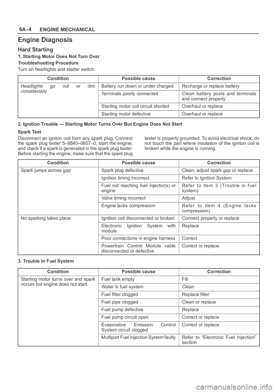
Engine Diagnosis
Hard Starting
1. Starting Motor Does Not Turn Over
Troubleshooting Procedure
Turn on headlights and starter switch.
Condition
Possible causeCorrection
Headlights go out or dim
considerably
Battery run down or under chargedRecharge or replace battery
considerablyTerminals poorly connectedClean battery posts and terminals
and connect properly
Starting motor coil circuit shortedOverhaul or replace
Starting motor defectiveOverhaul or replace
2. Ignition Trouble — Starting Motor Turns Over But Engine Does Not Start
Spark Test
Disconnect an igniton coil from any spark plug. Connect
the spark plug tester 5–8840–0607–0, start the engine,
a n d c h e c k i f a s p a r k i s g e n e r a t e d in t h e s p a r k p l u g t e s t e r.
Before starting the engine, make sure that the spark plugtester is properly grounded. To avoid electrical shock, do
not touch the part where insulation of the igniton coil is
broken while the engine is running.
Condition
Possible causeCorrection
Spark jumps across gapSpark plug defectiveClean, adjust spark gap or replace
Ignition timing incorrectRefer to Ignition System
Fuel not reaching fuel injector(s) or
engineRefer to item 3 (Trouble in fuel
system)
Valve timing incorrectAdjust
Engine lacks compressionRefer to item 4 (Engine lacks
compression)
No sparking takes placeIgnition coil disconnected or brokenConnect properly or replace
Electronic Ignition System with
moduleReplace
Poor connections in engine harnessCorrect
Powertrain Control Module cable
disconnected or defectiveCorrect or replace
3. Trouble In Fuel System
Condition
Possible causeCorrection
Starting motor turns over and spark
occurs but engine does not start
Fuel tank emptyFill
occurs but engine does not start.Water in fuel systemClean
Fuel filter cloggedReplace filter
Fuel pipe cloggedClean or replace
Fuel pump defectiveReplace
Fuel pump circuit openCorrect or replace
Evaporative Emission Control
System circuit cloggedCorrect or replace
Multiport Fuel Injection System faultyRefer to “Electronic Fuel Injection”
section
Page 963 of 6000

6A–7
ENGINE MECHANICAL
Condition CorrectionPossible cause
OthersEngine lacks compressionRefer to “Hard Start”
Valve incorrectly seatedLap valve
Air Cleaner Filter cloggedReplace filter element
Valve timing incorrectReadjust
Idle air control valve brokenReplace
Fast idle solenoid defectiveReplace
Positive Crankcase Ventilation valve
defective or cloggedReplace
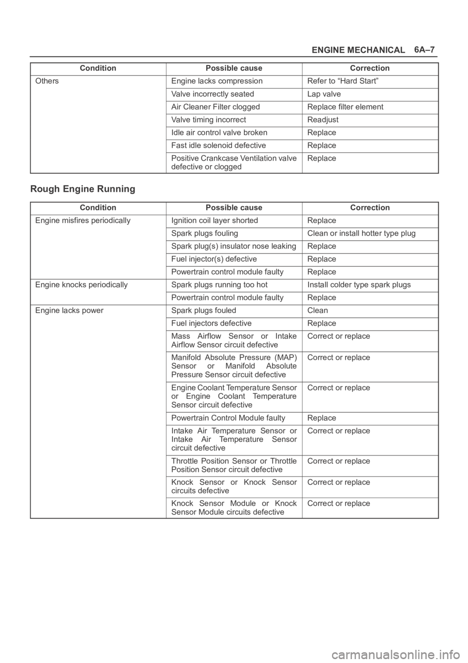
Rough Engine Running
ConditionPossible causeCorrection
Engine misfires periodicallyIgnition coil layer shortedReplace
Spark plugs foulingClean or install hotter type plug
Spark plug(s) insulator nose leakingReplace
Fuel injector(s) defectiveReplace
Powertrain control module faultyReplace
Engine knocks periodicallySpark plugs running too hotInstall colder type spark plugs
Powertrain control module faultyReplace
Engine lacks powerSpark plugs fouledClean
Fuel injectors defectiveReplace
Mass Airflow Sensor or Intake
Airflow Sensor circuit defectiveCorrect or replace
Manifold Absolute Pressure (MAP)
Sensor or Manifold Absolute
Pressure Sensor circuit defectiveCorrect or replace
Engine Coolant Temperature Sensor
or Engine Coolant Temperature
Sensor circuit defectiveCorrect or replace
Powertrain Control Module faultyReplace
Intake Air Temperature Sensor or
Intake Air Temperature Sensor
circuit defectiveCorrect or replace
Throttle Position Sensor or Throttle
Position Sensor circuit defectiveCorrect or replace
Knock Sensor or Knock Sensor
circuits defectiveCorrect or replace
Knock Sensor Module or Knock
Sensor Module circuits defectiveCorrect or replace
Page 966 of 6000

6A–10
ENGINE MECHANICAL
Engine Lacks Power
ConditionPossible causeCorrection
Trouble in fuel systemFuel Pressure Control Valve not
working normallyReplace
Fuel injector cloggedClean or replace
Fuel pipe cloggedClean
Fuel filter clogged or fouledReplace
Fuel pump drive circuit not working
normallyCorrect or replace
Fuel tank not sufficiently breathing
due to clogged Evaporative
Emission Control System circuitClean or replace
Water in fuel systemClean
Inferior quality fuel in fuel systemUse fuel of specified octane rating
Powertrain Control Module supplied
poor voltageCorrect circuit
Throttle Position Sensor cable
broken or poor connectionsCorrect or replace
Throttle Position Sensor defectiveReplace
Mass Airflow Sensor not working
normallyReplace
Manifold Absolute Pressure Sensor
not working normallyReplace
Intake Air Temperature Sensor not
working normallyReplace
Engine Coolant Temperature Sensor
circuit open or shortedCorrect or replace
Engine Coolant Temperature Sensor
defectiveReplace
Powertrain Control Module defectiveReplace
Trouble in intake or exhaust systemAir Cleaner Filter cloggedReplace filter element
Air duct kinked or flattenedCorrect or replace
Ignition failure————Refer to Hard Start Troubleshooting
Guide
Heat range of spark plug inadequateInstall spark plugs of adequate heat
range
Ignition coil defectiveReplace
Page 970 of 6000

6A–14
ENGINE MECHANICAL
Condition CorrectionPossible cause
Trouble in emission control systemHeated Oxygen Sensor circuit openCorrect or replace
Heated Oxygen Sensor defectiveReplace
Signal vacuum hose loosely fitted or
defectiveCorrect or replace
EGR Valve circuit open or shortedCorrect or replace
Exhaust Gas Recirculation Valve
defectiveReplace
ECT Sensor circuit open or shortedCorrect or replace
Canister Purge Valve circuit open or
shortedCorrect or replace
Canister Purge Valve defectiveReplace
ECT Sensor defectiveReplace
Positive Crankcase Ventilation
(PCV) valve and hose cloggedCorrect or replace
Evaporator systemRefer to Section 6E
Trouble in ignition system————Refer to “Engine Lacks Power”
Trouble in cylinder head partsCarbon deposits in combustion
chamberRemove carbon
Carbon deposit on valve, valve seat
and valve guideRemove carbon
Engine Oil Consumption Excessive
ConditionPossible causeCorrection
Oil leakingOil pan drain plug looseRetighten or replace gasket
Crankcase fixing bolts loosenedRetighten
Oil pan setting bolts loosenedRetighten
Oil pan gasket brokenReplace gasket
Front cover retaining bolts loose or
gasket brokenRetighten or replace gasket
Head cover fixing bolts loose or
gasket brokenRetighten or replace gasket
Oil cooler adapter crackedReplace
Oil cooler center bolt looseRetighten
Oil cooler O–ring brokenReplace
Oil cooler piping loose or brokenRetighten or replace
Oil filter adapter crackedReplace
Oil filter attaching bolt loose or rubber
gasket brokenRetighten or replace oil filter
Oil cooler brokenReplace
Crankshaft front or rear oil seal
defectiveReplace oil seal
Oil pressure unit loose or brokenRetighten or replace
Blow–by gas hose brokenReplace hose
Positive Crankcase Ventilation Valve
cloggedClean
Engine/Transmission coupling failedReplace oil seal
Page 972 of 6000

6A–16
ENGINE MECHANICAL
Lubrication Problems
ConditionPossible causeCorrection
Oil pressure too lowWrong oil in useReplace with correct engine oil
Relief valve stickingReplace
Oil pump not operating properlyCorrect or replace
Oil pump strainer cloggedClean or replace strainer
Oil pump wornReplace
Oil pressure gauge defectiveCorrect or replace
Crankshaft bearing or connecting
rod bearing wornReplace
Oil contaminationWrong oil in useReplace with correct engine oil
Oil filter cloggedReplace oil filter
Cylinder head gasket damageReplace gasket
Burned gases leakingReplace piston and piston rings or
cylinder body assembly
Oil not reaching valve systemOil passage in cylinder head or
cylinder body cloggedClean or correct
Engine Oil Pressure Check
1. Check for dirt, gasoline or water in the engine oil.
a. Check the viscosity of the oil.
b. Change the oil if the viscosity is outside the
specified standard.
c. Refer to the “Maintenance and Lubrication” section
of this manual.
2. Check the engine oil level.
The level should fall somewhere between the “ADD”
and the “FULL” marks on the oil level dipstick.
If the oil level does not reach the “ADD” mark on the
oil level dipstick, engine oil must be added.3. Remove the oil pressure unit.
4. Install an oil pressure gauge.
5. Start the engine and allow the engine to reach normal
operating temperature (About 80
C).
6. Measure the oil pressure.
Oil pressure should be:
392–550 kPa (56.9–80.4 psi) at 3000 rpm.
7. Stop the engine.
8. Remove the oil pressure gauge.
9. Install the oil pressure unit.
10. Start the engine and check for leaks.
Page 997 of 6000

6A–41
ENGINE MECHANICAL
3. Remove oil strainer fixing bolts, remove oil strainer
assembly with O-ring.
050RW002
Legend
(1) Oil Pump
(2) Oil Strainer
(3) Oil Gallery
(4) From Oil Filter
(5) To Oil Filter
4. Remove three fixing bolts, oil pipe with O-ring.
5. Remove eight fixing bolts, oil gallery.
6. Remove piston with connecting rod assembly, before
removing the bearing cap, remove carbon on the top
of cylinder bore and push piston with connecting rod
out from the top of cylinder bore.
Installation
1. Install piston with connecting rod assembly.
Apply engine oil to cylinder bore, connecting rod
bearing and crank pin.
When installing the piston, its front mark must face
the engine front side.
The bearing cap number must be the same as
connecting rod number.
Apply engine oil to the thread and seating surface of
each nut.
Tighten nuts to the specified torque.
Torque : 54 Nꞏm (5.5 Kgꞏm/40 lb ft)
After tightening the nuts, make sure that the
crankshaft rotates smoothly.
NOTE: Do not apply engine oil to the bearing back faces
and connecting rod bearing fitting surfaces.
015RW003
Legend
(1) Piston Front Mark
(2) Piston Grade
(3) Connecting Rod Front Mark
2. Install oil gallery and tighten the bolts in two steps, in
the order shown in illustration.
To r q u e :
1st step : 29 Nꞏm (3.0 Kgꞏm/21 lb ft)
2nd step : 55
–65
051RS009
3. Install oil pipe with O-ring.
Torque : 10 Nꞏm (1.0 Kgꞏm/89 lb in)
4. Install oil strainer assembly with O-ring.
Torque : 25 Nꞏm (2.5 Kgꞏm/18 lb ft)
5. Install crankcase with Oil Pan.
Refer to installation procedure for Oil Pan and
Crankcase in this manual.
6. Install cylinder head assembly.
Refer to installation procedure for Cylinder Head in
this manual.
Page 1155 of 6000

6E–38
ENGINE DRIVEABILITY AND EMISSIONS
General Service Information
OBD Serviceablity Issues
The list of non-vehicle faults that could affect the
performance of the OBD system has been compiled.
These non-vehicle faults vary from environmental
conditions to the quality of fuel used.
The illumination of the MIL (“Check Engine” lamp) due to
a non-vehicle fault could lead to misdiagnosis of the
vehicle, increased warranty expense and customer
dissatisfaction. The following list of non-vehicle faults
does not include every possible fault and may not apply
equally to all product lines.
Fuel Quality
Using fuel with the wrong octane rating for your vehicle
may cause driveability problems. Many of the major fuel
companies advertise that using “premium” gasoline will
improve the performance of your vehicle. Most premium
fuels use alcohol to increase the octane rating of the fuel.
Although alcohol-enhanced fuels may raise the octane
rating, the fuel’s ability to turn into vapor in cold
temperatures deteriorates. This may affect the starting
ability and cold driveability of the engine.
Low fuel levels can lead to fuel starvation, lean engine
operation, and eventually engine misfire.
Non-OEM Parts
All of the OBD diagnostics have been calibrated to run
with OEM parts. Something as simple as a
high-performance exhaust system that affects exhaust
system back pressure could potentially interfere with the
operation of the EGR valve and thereby turn on the MIL
(“Check Engine” lamp). Small leaks in the exhaust
system near the post catalyst oxygen sensor can also
cause the MIL (“Check Engine” lamp) to turn on.
Aftermarket electronics, such as cellular phones,
stereos, and anti-theft devices, may radiate EMI into the
control system if they are improperly installed. This may
cause a false sensor reading and turn on the MIL (“Check
Engine” lamp).
Environment
Temporary environmental conditions, such as localized
flooding, will have an effect on the vehicle ignition system.
If the ignition system is rain-soaked, it can temporarily
cause engine misfire and turn on the MIL (“Check Engine”
lamp).
Poor Vehicle Maintenance
The sensitivity of OBD diagnostics will cause the MIL
(“Check Engine” lamp) to turn on if the vehicle is not
maintained properly. Restricted air filters, fuel filters, and
crankcase deposits due to lack of oil changes or improper
oil viscosity can trigger actual vehicle faults that were not
previously monitored prior to OBD. Poor vehicle
maintenance can not be classified as a “non-vehicle
fault”, but with the sensitivity of OBD diagnostics, vehicle
maintenance schedules must be more closely followed.Related System Faults
Many of the OBD system diagnostics will not run if the
PCM detects a fault on a related system or component.
One example would be that if the PCM detected a Misfire
fault, the diagnostics on the catalytic converter would be
suspended until Misfire fault was repaired. If the Misfire
fault was severe enough, the catalytic converter could be
damaged due to overheating and would never set a
Catalyst DTC until the Misfire fault was repaired and the
Catalyst diagnostic was allowed to run to completion. If
this happens, the customer may have to make two trips to
the dealership in order to repair the vehicle.
Maintenance Schedule
Refer to the Maintenance Schedule.
Visual / Physical Engine Compartment
Inspection
Perform a careful visual and physical engine
compartment inspection when performing any diagnostic
procedure or diagnosing the cause of an emission test
failure. This can often lead to repairing a problem without
further steps. Use the following guidelines when
performing a visual/physical inspection:
Inspect all vacuum hoses for punches, cuts,
disconnects, and correct routing.
Inspect hoses that are difficult to see behind other
components.
Inspect all wires in the engine compartment for proper
connections, burned or chafed spots, pinched wires,
contact with sharp edges or contact with hot exhaust
manifolds or pipes.
Basic Knowledge of Tools Required
NOTE: Lack of basic knowledge of this powertrain when
performing diagnostic procedures could result in an
incorrect diagnosis or damage to powertrain
components. Do not attempt to diagnose a powertrain
problem without this basic knowledge.
A basic understanding of hand tools is necessary to effec-
tively use this section of the Service Manual.
Serial Data Communications
Class II Serial Data Communications
This vehicle utilizes the “Class II” communication system.
Each bit of information can have one of two lengths: long
or short. This allows vehicle wiring to be reduced by
transmitting and receiving multiple signals over a single
wire. The messages carried on Class II data streams are
also prioritized. If two messages attempt to establish
communications on the data line at the same time, only
the message with higher priority will continue. The device
with the lower priority message must wait. The most
significant result of this regulation is that it provides Tech 2
manufacturers with the capability to access data from any
make or model vehicle that is sold.