1998 OPEL FRONTERA oil filter
[x] Cancel search: oil filterPage 1734 of 6000

ENGINE MECHANICAL 6A – 1
ENGINE
ENGINE MECHANICAL
CONTENTS
General Description . . . . . . . . . . . . . . . . . . . . 6A–2
Service Information . . . . . . . . . . . . . . . . . . . . 6A–3
Service Standard . . . . . . . . . . . . . . . . . . . . . . 6A–6
Servicing . . . . . . . . . . . . . . . . . . . . . . . . . . . . 6A–9
Tightening Torque . . . . . . . . . . . . . . . . . . . . . 6A–14
Special Tools . . . . . . . . . . . . . . . . . . . . . . . . . 6A–25
Engine Assembly . . . . . . . . . . . . . . . . . . . . . . 6A–28
Engine Mount (RH) . . . . . . . . . . . . . . . . . . . . 6A–30
Engine Mount (LH). . . . . . . . . . . . . . . . . . . . . 6A–31
Intercooler . . . . . . . . . . . . . . . . . . . . . . . . . . . 6A–32
Cylinder Head Cover . . . . . . . . . . . . . . . . . . . 6A–33
Intake Manifold . . . . . . . . . . . . . . . . . . . . . . . 6A–35
Exhaust Manifold . . . . . . . . . . . . . . . . . . . . . . 6A–36
Turbocharger . . . . . . . . . . . . . . . . . . . . . . . . . 6A–38Cylinder Head . . . . . . . . . . . . . . . . . . . . . . . . 6A–41
Cylinder Head Gasket . . . . . . . . . . . . . . . . . . 6A–43
Camshaft . . . . . . . . . . . . . . . . . . . . . . . . . . . . 6A–47
Timing Gear . . . . . . . . . . . . . . . . . . . . . . . . . . 6A–52
Valve Stem Seal, Valve Spring and Adjuster . . 6A–60
Valve Clearance Adjustment. . . . . . . . . . . . . . 6A–67
Oil Rail and Injector . . . . . . . . . . . . . . . . . . . . 6A–69
Crank Case . . . . . . . . . . . . . . . . . . . . . . . . . . 6A–72
Crankshaft . . . . . . . . . . . . . . . . . . . . . . . . . . . 6A–74
Piston and Connecting Rod . . . . . . . . . . . . . . 6A–84
Cylinder Block . . . . . . . . . . . . . . . . . . . . . . . . 6A–92
Oil Pump Assembly . . . . . . . . . . . . . . . . . . . . 6A–98
Oil Filter Cartridge . . . . . . . . . . . . . . . . . . . . . 6A–99
Oil Cooler . . . . . . . . . . . . . . . . . . . . . . . . . . . 6A–99
Page 1736 of 6000

ENGINE MECHANICAL 6A – 3
SERVICE INFORMATION
MAIN DATA AND SPECIFICATION
Engine type Diesel, four cycle water cooled inline
Camshaft type DOHC
Number of cylinders 4
Bore x stroke (mm) 95.4 x 104.9
Total piston displacement (cc) 2999
Compression ratio (to 1) 19.0
For Europe : 18.5
Engine weight (dry) N (kg/lb) 2492 (254/560) (A/T)
For Europe : 2422 (247/545) (A/T)
2649 (270/593) (M/T)
For Europe : 2697 (275/606) (M/T)
Engine idling speed (Reference) RPM 720
Compression pressure kpa (kg/cm
2/psi)-rpm 3040 (31/441)-200
Firing order 1–3–4–2
VALVE SYSTEM
Intake valves open at: B.T.D.C. 3°
close at: A.B.D.C. 57.6°
Exhaust valves open at: B.B.D.C. 56.5°
close at: A.T.D.C. 5°
Valve clearance (at cold) mm (in)
intake: 0.15 (0.006)
exhaust: 0.25 (0.01)
Oil filter Full flow and bypass combined type
Oil capacity (Original factory fill or rebuilt engine) 9.0 liters (7.9 US quarts)
Oil capacity (Service change)
with filter change 6.0 liters (6.3 US quarts)
without filter change 5.0 liters (5.3 US quarts)
Oil cooler Water cooled type
Inter cooler Air cooled type
Turbocharger method
Control method Wastegate control
Lubrication Pressurized control
Cooling method Coolant cooled
Crankshaft
As tufftriding (Nitrizing treatment) is applied to increase
crankshaft strength, crankpins and journals should not
be reground.
Piston Cooling
An oiling jet device for piston cooling is provided in the
lubricating oil circuit from the cylinder block oil gallery
via a check valve.
Take care not to damage any oiling jet when removing
and installing piston and connecting assembly.
Fuel Injection System
The injection system is oil rail type.
Quick On Start 4 System
QOS4 preheating system which features a quick-on
glow plug with thermometer control of the glowing time
and the afterglow time function, is applied.
Page 1742 of 6000

ENGINE MECHANICAL 6A – 9
SERVICING
Servicing refers to general maintenance procedures to
be performed by qualified service personnel.
MODEL IDENTIFICATION
Engine Serial Number
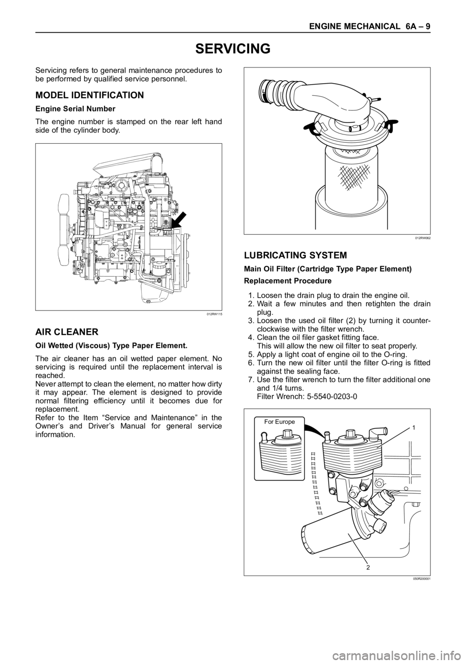
The engine number is stamped on the rear left hand
side of the cylinder body.
AIR CLEANER
Oil Wetted (Viscous) Type Paper Element.
The air cleaner has an oil wetted paper element. No
servicing is required until the replacement interval is
reached.
Never attempt to clean the element, no matter how dirty
it may appear. The element is designed to provide
normal filtering efficiency until it becomes due for
replacement.
Refer to the Item “Service and Maintenance” in the
Owner’s and Driver’s Manual for general service
information.
LUBRICATING SYSTEM
Main Oil Filter (Cartridge Type Paper Element)
Replacement Procedure
1. Loosen the drain plug to drain the engine oil.
2. Wait a few minutes and then retighten the drain
plug.
3. Loosen the used oil filter (2) by turning it counter-
clockwise with the filter wrench.
4. Clean the oil filer gasket fitting face.
This will allow the new oil filter to seat properly.
5. Apply a light coat of engine oil to the O-ring.
6. Turn the new oil filter until the filter O-ring is fitted
against the sealing face.
7. Use the filter wrench to turn the filter additional one
and 1/4 turns.
Filter Wrench: 5-5540-0203-0
012RW115
012RW062
For Europe1
2
050R200001
Page 1743 of 6000

6A – 10 ENGINE MECHANICAL
8. Check the engine oil level and replenish to the
specified level if required.
9. Start the engine and check for oil leakage from the
main oil filter.
FUEL SYSTEM
Fuel filter
Replacement Procedure
1. Loosen the used fuel filter by turning it
counterclockwise with the filter wrench.
Filter Wrench : 5-8840-0203-0
2. Clean the filter cover fitting faces.
This will allow the new fuel filter to seat properly.
3. Apply a light coat of engine oil to the O-ring.
4. Turn the fuel filter until the sealing face comes in
contact with the O-ring.
5. Turn the fuel filter with a filter wrench 2/3 of a turn
until sealed.
Filter Wrench: 5-8840-0203-0Legend
(1) Priming pump
6. Operate the priming pump until the air is discharged
completely from fuel system.
NOTE: The use of an Isuzu genuine fuel filter is
strongly recommended.
COOLING SYSTEM
Coolant Level
Check the coolant level and replenish the radiator
reserve tank as necessary.
If the coolant level falls below the “‘MIN” line, carefully
check the cooling system for leakage. Then add
enough coolant to bring the level up to the “MAX” line.
NOTE: Do not overfill the reserve tank.
012RW112
012RW078
1
012RW111
012RW080
Page 1832 of 6000

ENGINE MECHANICAL 6A – 99
OIL COOLER
For Europe1
2050R200001
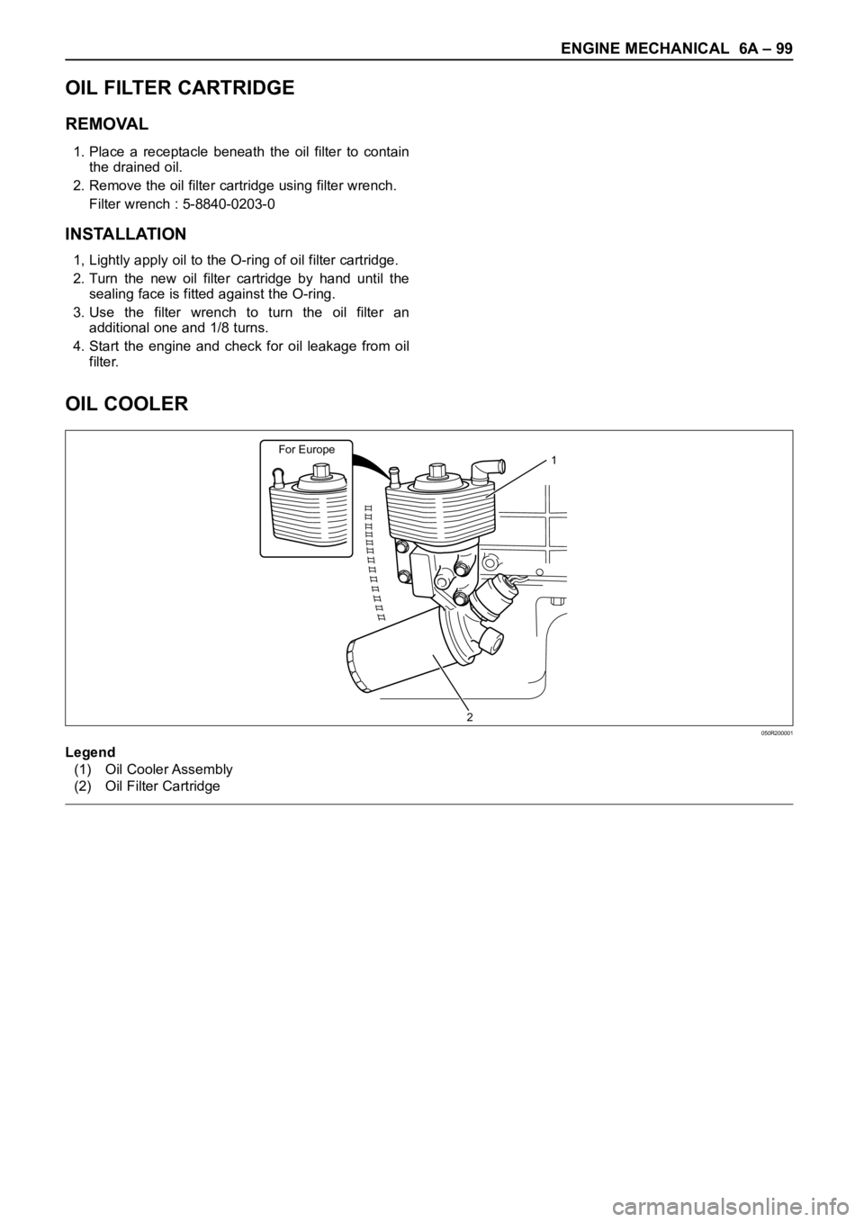
Legend
(1) Oil Cooler Assembly
(2) Oil Filter Cartridge
OIL FILTER CARTRIDGE
REMOVAL
1. Place a receptacle beneath the oil filter to contain
the drained oil.
2. Remove the oil filter cartridge using filter wrench.
Filter wrench : 5-8840-0203-0
INSTALLATION
1, Lightly apply oil to the O-ring of oil filter cartridge.
2. Turn the new oil filter cartridge by hand until the
sealing face is fitted against the O-ring.
3. Use the filter wrench to turn the oil filter an
additional one and 1/8 turns.
4. Start the engine and check for oil leakage from oil
filter.
Page 1846 of 6000

ENGINE FUEL 6C – 1
ENGINE FUEL
CONTENTS
GENERAL DESCRIPTION
General Description . . . . . . . . . . . . . . . . . . 6C–1
On-Vehicle Service . . . . . . . . . . . . . . . . . . 6C–7
Fuel Filter Assembly . . . . . . . . . . . . . . . . 6C–7
Fuel Filter Cartridge . . . . . . . . . . . . . . . . 6C–7
Injector . . . . . . . . . . . . . . . . . . . . . . . . . . 6C–9
Fuel Pump Pipe . . . . . . . . . . . . . . . . . . . 6C–13High Pressure Oil Pump . . . . . . . . . . . . . 6C–15
Fuel Tank . . . . . . . . . . . . . . . . . . . . . . . . 6C–20
Fuel Gauge Unit . . . . . . . . . . . . . . . . . . . 6C–21
Fuel Filler Cap . . . . . . . . . . . . . . . . . . . . 6C–21
To realize the compatibility between low exhaust
emission and high engine output, an HEUI
(Hydraulically actuated Electronically controlled Unit
Injector) system, has been introduced. This system is
comprised of a hydraulic system, fuel system, and
electronic control system, using a high-pressure oil
pump in place of the conventional fuel injection pump.
The oil pressurized by means of this pump and by
signals from the ECM (Electronic Control Module)
actuates the fuel injector provided for each cylinder.
Inside of the fuel injector, fuel pressure is increased due
to the high-pressure oil. The ECM detects the driving
state of the vehicle, forms, signals sent by engine and
other part sensors, which determines the optimum fuel
injection amount and timing, thus controlling the fuel
injectors. Thus high engine output, good fuel economy,
and low exhaust emission are realized.When working on the fuel system, there are several
things to keep in mind:
1) Any time the fuel system is being worked on,
disconnect the negative battery cable except for
those tests where battery voltage is required.
2) Always keep a dry chemical (Class B) fire
extinguisher near the work area.
3) Replace all pipes with the same pipe and fittings
that were removed.
Clean and inspect “O” rings. Replace where
required.
4) Always relieve the line pressure before servicing
any fuel system components.
5) Do not attempt repairs on the fuel system until you
have read the instructions and checked the pictures
relating to that repair.
6) After maintenance work, push priming pump and
send enough fuel to the fuel system before starting
the engine.
NOTE: In comparison with the conventional engine,
the capacity of fuel passage in the 4JX1 engine is
larger. It takes the priming pump more time to fill the
engine with fuel.
Page 1847 of 6000

6C – 2 ENGINE FUEL
FUEL FLOW
1
14 Except above region
89
10111
2
2
4
12
5 6
7
3
13
14 For Europe, Nicaragua,
Argentina, Philippin
11
4
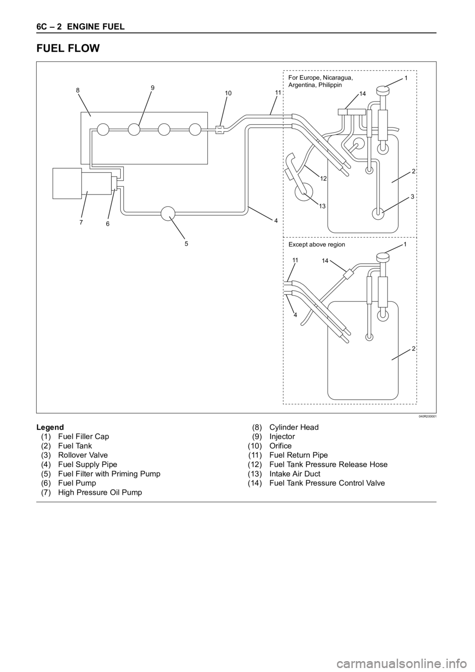
Legend
(1) Fuel Filler Cap
(2) Fuel Tank
(3) Rollover Valve
(4) Fuel Supply Pipe
(5) Fuel Filter with Priming Pump
(6) Fuel Pump
(7) High Pressure Oil Pump(8) Cylinder Head
(9) Injector
(10) Orifice
(11) Fuel Return Pipe
(12) Fuel Tank Pressure Release Hose
(13) Intake Air Duct
(14) Fuel Tank Pressure Control Valve
040R200001
Page 1849 of 6000

6C – 4 ENGINE FUEL
HIGH PRESSURE OIL PUMP, OIL FLOW
P
33
32
31
30
1
2
3
4
56
8
97
10
11
12
13
14 23 29
25
28
27262415
16
17 18
19 20 21 22
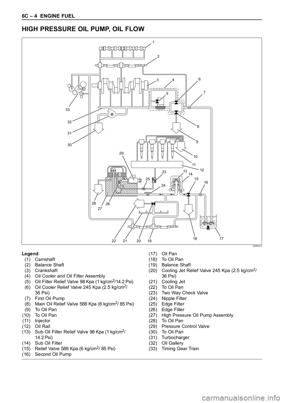
Legend
(1) Camshaft
(2) Balance Shaft
(3) Crankshaft
(4) Oil Cooler and Oil Filter Assembly
(5) Oil Filter Relief Valve 98 Kpa (1 kg/cm
2/14.2 Psi)
(6) Oil Cooler Relief Valve 245 Kpa (2.5 kg/cm2/
36 Psi)
(7) First Oil Pump
(8) Main Oil Relief Valve 588 Kpa (6 kg/cm
2/ 85 Psi)
(9) To Oil Pan
(10) To Oil Pan
(11) Injector
(12) Oil Rail
(13) Sub Oil Filter Relief Valve 98 Kpa (1 kg/cm
2/
14.2 Psi)
(14) Sub Oil Filter
(15) Relief Valve 588 Kpa (6 kg/cm
2/ 85 Psi)
(16) Second Oil Pump(17) Oil Pan
(18) To Oil Pan
(19) Balance Shaft
(20) Cooling Jet Relief Valve 245 Kpa (2.5 kg/cm
2/
36 Psi)
(21) Cooling Jet
(22) To Oil Pan
(23) Two Way Check Valve
(24) Nipple Filter
(25) Edge Filter
(26) Edge Filter
(27) High Pressure Oil Pump Assembly
(28) To Oil Pan
(29) Pressure Control Valve
(30) To Oil Pan
(31) Turbocharger
(32) Oil Gallery
(33) Timing Gear Train
040RW018