1998 OPEL FRONTERA oil filter
[x] Cancel search: oil filterPage 2173 of 6000
7A–19 AUTOMATIC TRANSMISSION (4L30–E)
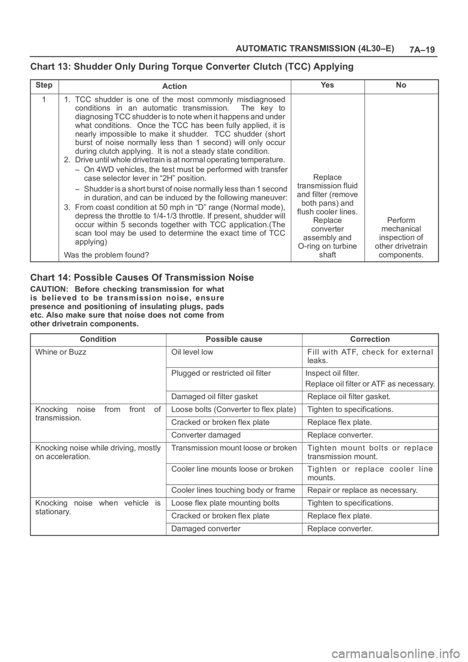
Chart 13: Shudder Only During Torque Converter Clutch (TCC) Applying
StepActionYe sNo
11. TCC shudder is one of the most commonly misdiagnosed
conditions in an automatic transmission. The key to
diagnosing TCC shudder is to note when it happens and under
what conditions. Once the TCC has been fully applied, it is
nearly impossible to make it shudder. TCC shudder (short
burst of noise normally less than 1 second) will only occur
during clutch applying. It is not a steady state condition.
2. Drive until whole drivetrain is at normal operating temperature.
– On 4WD vehicles, the test must be performed with transfer
case selector lever in “2H” position.
– Shudder is a short burst of noise normally less than 1 second
in duration, and can be induced by the following maneuver:
3. From coast condition at 50 mph in “D” range (Normal mode),
depress the throttle to 1/4-1/3 throttle. If present, shudder will
occur within 5 seconds together with TCC application.(The
scan tool may be used to determine the exact time of TCC
applying)
Was the problem found?
Replace
transmission fluid
and filter (remove
both pans) and
flush cooler lines.
Replace
converter
assembly and
O-ring on turbine
shaft
Perform
mechanical
inspection of
other drivetrain
components.
Chart 14: Possible Causes Of Transmission Noise
CAUTION: Before checking transmission for what
is believed to be transmission noise, ensure
presence and positioning of insulating plugs, pads
etc. Also make sure that noise does not come from
other drivetrain components.
Condition
Possible causeCorrection
Whine or BuzzOil level lowFill with ATF, check for external
leaks.
Plugged or restricted oil filterInspect oil filter.
Replace oil filter or ATF as necessary.
Damaged oil filter gasketReplace oil filter gasket.
Knocking noise from front of
transmission
Loose bolts (Converter to flex plate)Tighten to specifications.
transmission.Cracked or broken flex plateReplace flex plate.
Converter damagedReplace converter.
Knocking noise while driving, mostly
on acceleration.Transmission mount loose or brokenTighten mount bolts or replace
transmission mount.
Cooler line mounts loose or brokenTighten or replace cooler line
mounts.
Cooler lines touching body or frameRepair or replace as necessary.
Knocking noise when vehicle is
stationary
Loose flex plate mounting boltsTighten to specifications.
stationary.Cracked or broken flex plateReplace flex plate.
Damaged converterReplace converter.
Page 2174 of 6000
7A–20
AUTOMATIC TRANSMISSION (4L30–E)
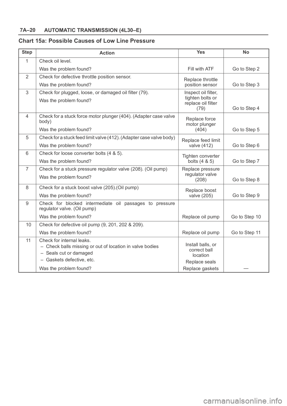
Chart 15a: Possible Causes of Low Line Pressure
StepActionYe sNo
1Check oil level.
Was the problem found?
Fill with ATFGo to Step 2
2Check for defective throttle position sensor.
Was the problem found?Replace throttle
position sensor
Go to Step 3
3Check for plugged, loose, or damaged oil filter (79).
Was the problem found?Inspect oil filter,
tighten bolts or
replace oil filter
(79)
Go to Step 4
4Check for a stuck force motor plunger (404). (Adapter case valve
body)
Was the problem found?Replace force
motor plunger
(404)
Go to Step 5
5Check for a stuck feed limit valve (412). (Adapter case valve body)
Was the problem found?Replace feed limit
valve (412)
Go to Step 6
6Check for loose converter bolts (4 & 5).
Was the problem found?Tighten converter
bolts (4 & 5)
Go to Step 7
7Check for a stuck pressure regulator valve (208). (Oil pump)
Was the problem found?Replace pressure
regulator valve
(208)
Go to Step 8
8Check for a stuck boost valve (205).(Oil pump)
Was the problem found?Replace boost
valve (205)
Go to Step 9
9Check for blocked intermediate oil passages to pressure
regulator valve. (Oil pump)
Was the problem found?
Replace oil pumpGo to Step 10
10Check for defective oil pump (9, 201, 202 & 209).
Was the problem found?
Replace oil pumpGo to Step 11
11Check for internal leaks.
– Check balls missing or out of location in valve bodies
– Seals cut or damaged
– Gaskets defective, etc.
Was the problem found?Install balls, or
correct ball
location
Replace seals
Replace gaskets
—
Page 2190 of 6000
7A–36
AUTOMATIC TRANSMISSION (4L30–E)
Solenoid (Main Case Valve Body)
Removal
1. Raise the vehicle and support it on jack stands.
2. Disconnect battery ground cable.
3. Remove transfer and exhaust protectors.
4. Drain fluid.
5. Remove exhaust pipe and disconnect oxygen sensor
connector.
6. Support transfer case with a jack and remove third
crossmember.
7. Remove sixteen 10 mm screws, main case oil pan,
magnet, and gasket.
8. Remove three 13 mm screws, oil filter.
9. Disconnect wiring harness from band control
solenoid and shift solenoids. Pull only on connectors,
not on wiring harness.
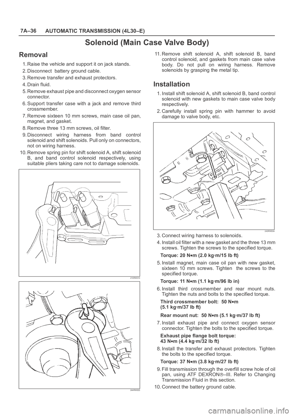
10. Remove spring pin for shift solenoid A, shift solenoid
B, and band control solenoid respectively, using
suitable pliers taking care not to damage solenoids.
210RW010
244RW003
11. Remove shift solenoid A, shift solenoid B, band
control solenoid, and gaskets from main case valve
body. Do not pull on wiring harness. Remove
solenoids by grasping the metal tip.
Installation
1. Install shift solenoid A, shift solenoid B, band control
solenoid with new gaskets to main case valve body
respectively.
2. Carefully install spring pin with hammer to avoid
damage to valve body, etc.
243RW004
3. Connect wiring harness to solenoids.
4. Install oil filter with a new gasket and the three 13 mm
screws. Tighten the screws to the specified torque.
To r q u e : 2 0 N
m (2.0 kgꞏm/15 lb ft)
5. Install magnet, main case oil pan with new gasket,
sixteen 10 mm screws. Tighten the screws to the
specified torque.
To r q u e : 11 N
m (1.1 kgꞏm/96 lb in)
6. Install third crossmember and rear mount nuts.
Tighten the nuts and bolts to the specified torque.
Third crossmember bolt: 50 N
m
(5.1 kgꞏm/37 lb ft)
Rear mount nut: 50 N
m (5.1 kgꞏm/37 lb ft)
7. Install exhaust pipe and connect oxygen sensor
connector. Tighten the bolts to the specified torque.
Exhaust pipe flange bolt torque:
43 N
m(4.4kgꞏm/32lbft)
8. Install the transfer and exhaust protectors. Tighten
the bolts to the specified torque.
Torque: 37 N
m (3.8 kgꞏm/27 lb ft)
9. Fill transmission through the overfill screw hole of oil
pan, using ATF DEXRON
–III. Refer to Changing
Transmission Fluid in this section.
10. Connect the battery ground cable.
Page 2192 of 6000
7A–38
AUTOMATIC TRANSMISSION (4L30–E)
Valve Body Assembly (Main Case)
Removal
1. Raise the vehicle and support it on jack stands.
2. Disconnect battery ground cable.
3. Remove transfer and exhaust protectors.
4. Drain fluid.
5. Remove exhaust pipe and disconnect oxygen sensor
connector.
6. Support transfer case with a jack and remove third
crossmember.
7. Remove sixteen 10 mm screws, main case oil pan,
magnet and gasket.
8. Remove three 13 mm oil filter fixing screws, then
remove oil filter.
9. Remove two 13 mm manual detent fixing screws,
then remove roller and spring assembly.
10. Disconnect wiring harness from band control
solenoid and shift solenoids. Pull only on connectors,
not on wiring harness.
11. Remove four 13 mm servo cover fixing screws, then
remove servo cover and gasket.
12. Remove seven 13 mm valve body fixing screws.
Disconnect the ground wire from the main case
valve body.
13. Remove main case valve body with manual valve link
and transfer plate. Note the position of the link (long
end into valve, short end into range selector lever).
14. Remove transfer plate gasket from main case.
15. Remove two check balls from main case.
Installation
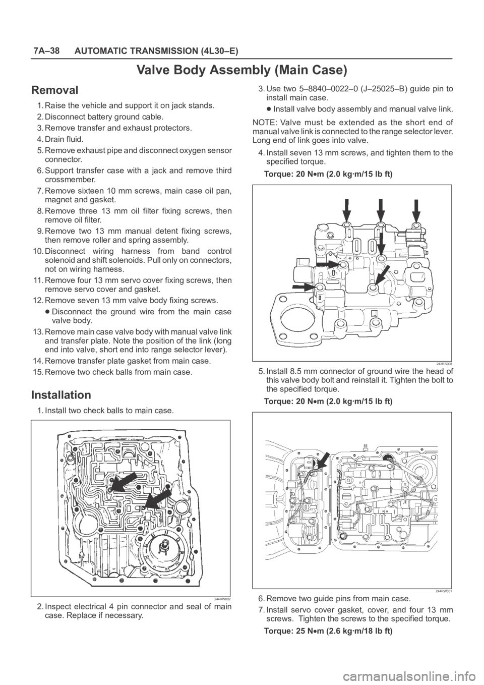
1. Install two check balls to main case.
244RW002
2. Inspect electrical 4 pin connector and seal of main
case. Replace if necessary.3. Use two 5–8840–0022–0 (J–25025–B) guide pin to
install main case.
Install valve body assembly and manual valve link.
NOTE: Valve must be extended as the short end of
manual valve link is connected to the range selector lever.
Long end of link goes into valve.
4. Install seven 13 mm screws, and tighten them to the
specified torque.
To r q u e : 2 0 N
m (2.0 kgꞏm/15 lb ft)
243RS008
5. Install 8.5 mm connector of ground wire the head of
this valve body bolt and reinstall it. Tighten the bolt to
the specified torque.
To r q u e : 2 0 N
m (2.0 kgꞏm/15 lb ft)
244RW001
6. Remove two guide pins from main case.
7. Install servo cover gasket, cover, and four 13 mm
screws. Tighten the screws to the specified torque.
To r q u e : 2 5 N
m (2.6 kgꞏm/18 lb ft)
Page 2193 of 6000
7A–39 AUTOMATIC TRANSMISSION (4L30–E)
8. Connect wiring harness to band control and shift
solenoids.
9. Install roller and spring assembly to manual detent.
Install two 13 mm screws, and tighten them to the
specified torque.
Torque: 20 N
m (2.0 kgꞏm/15 lb ft)
10. Install oil filter and three 13 mm screws. Tighten the
screws to the specified torque.
Torque : 20 N
m (2.0 kgꞏm/15 lb ft)
11. Install oil pan gasket, magnet, oil pan and sixteen 10
mm screws. Tighten the screws to the specified
torque.
Torque: 11 N
m (1.1 kgꞏm/96 lb in)
12. Install third crossmember and rear mount. Tighten the
bolts and nuts to the specified torque.
Torque
Third crossmember bolt:
50 N
m (5.1 kgꞏm/37 lb ft)
Rear mount nut: 50 N
m(5.1kgꞏm/37lbft)
13. Install exhaust pipe and connect oxygen sensor
connector. Tighten the bolts to the specified torque.
Exhaust pipe flange bolt torque:
43 N
m (4.4 kgꞏm/32 lb ft)
14. Install transfer and exhaust protectors. Tighten the
bolts to the specified torque.
Torque: 37 N
m (3.8 kgꞏm/27 lb ft)
15. Fill transmission through overfill screw hole of oil pan,
using ATF DEXRON
–III, refer to Changing
Transmission Fluid in this section.
16. Connect battery ground cable.
Page 2198 of 6000
7A–44
AUTOMATIC TRANSMISSION (4L30–E)
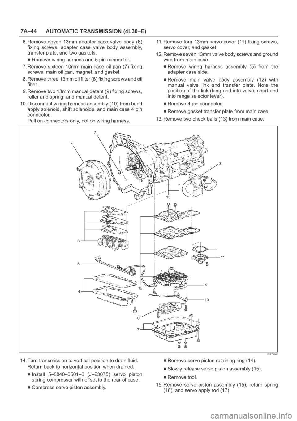
6. Remove seven 13mm adapter case valve body (6)
fixing screws, adapter case valve body assembly,
transfer plate, and two gaskets.
Remove wiring harness and 5 pin connector.
7. Remove sixteen 10mm main case oil pan (7) fixing
screws, main oil pan, magnet, and gasket.
8. Remove three 13mm oil filter (8) fixing screws and oil
filter.
9. Remove two 13mm manual detent (9) fixing screws,
roller and spring, and manual detent.
10. Disconnect wiring harness assembly (10) from band
apply solenoid, shift solenoids, and main case 4 pin
connector.
Pull on connectors only, not on wiring harness.11. Remove four 13mm servo cover (11) fixing screws,
servo cover, and gasket.
12. Remove seven 13mm valve body screws and ground
wire from main case.
Remove wiring harness assembly (5) from the
adapter case side.
Remove main valve body assembly (12) with
manual valve link and transfer plate. Note the
position of the link (long end into valve, short end
into range selector lever).
Remove 4 pin connector.
Remove gasket transfer plate from main case.
13. Remove two check balls (13) from main case.
240RW022
14. Turn transmission to vertical position to drain fluid.
Return back to horizontal position when drained.
Install 5–8840–0501–0 (J–23075) servo piston
spring compressor with offset to the rear of case.
Compress servo piston assembly.
Remove servo piston retaining ring (14).
Slowly release servo piston assembly (15).
Remove tool.
15. Remove servo piston assembly (15), return spring
(16), and servo apply rod (17).
Page 2209 of 6000
7A–55 AUTOMATIC TRANSMISSION (4L30–E)
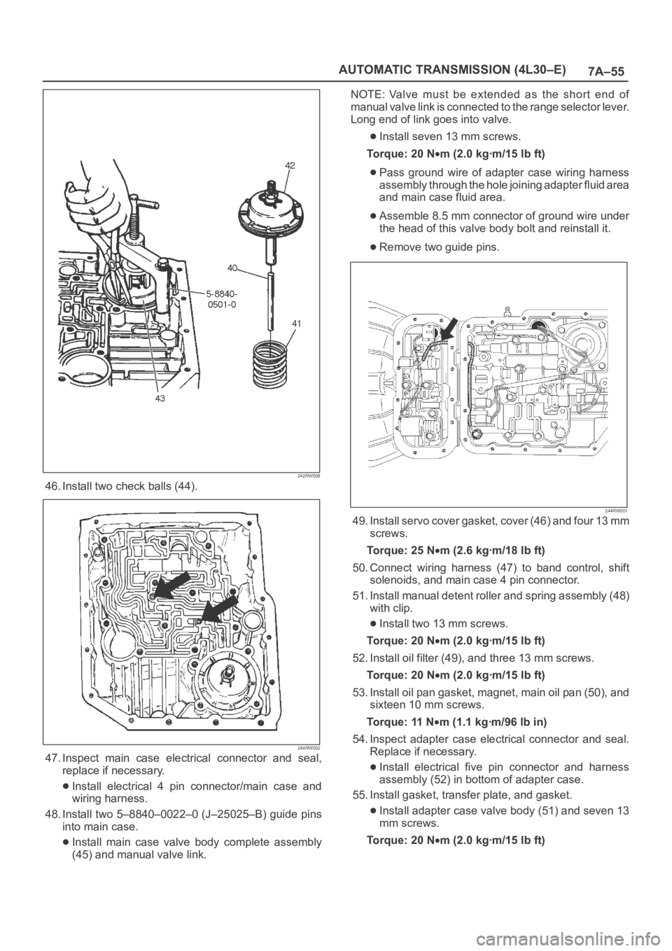
242RW008
46. Install two check balls (44).
244RW002
47. Inspect main case electrical connector and seal,
replace if necessary.
Install electrical 4 pin connector/main case and
wiring harness.
48. Install two 5–8840–0022–0 (J–25025–B) guide pins
into main case.
Install main case valve body complete assembly
(45) and manual valve link.NOTE: Valve must be extended as the short end of
manual valve link is connected to the range selector lever.
Long end of link goes into valve.
Install seven 13 mm screws.
To r q u e : 2 0 N
m (2.0 kgꞏm/15 lb ft)
Pass ground wire of adapter case wiring harness
assembly through the hole joining adapter fluid area
and main case fluid area.
Assemble 8.5 mm connector of ground wire under
the head of this valve body bolt and reinstall it.
Remove two guide pins.
244RW001
49. Install servo cover gasket, cover (46) and four 13 mm
screws.
To r q u e : 2 5 N
m (2.6 kgꞏm/18 lb ft)
50. Connect wiring harness (47) to band control, shift
solenoids, and main case 4 pin connector.
51. Install manual detent roller and spring assembly (48)
with clip.
Install two 13 mm screws.
To r q u e : 2 0 N
m (2.0 kgꞏm/15 lb ft)
52. Install oil filter (49), and three 13 mm screws.
To r q u e : 2 0 N
m (2.0 kgꞏm/15 lb ft)
53. Install oil pan gasket, magnet, main oil pan (50), and
sixteen 10 mm screws.
To r q u e : 11 N
m (1.1 kgꞏm/96 lb in)
54. Inspect adapter case electrical connector and seal.
Replace if necessary.
Install electrical five pin connector and harness
assembly (52) in bottom of adapter case.
55. Install gasket, transfer plate, and gasket.
Install adapter case valve body (51) and seven 13
mm screws.
Torque: 20 N
m (2.0 kgꞏm/15 lb ft)
Page 2239 of 6000
7A–85 AUTOMATIC TRANSMISSION (4L30–E)
(38) Seal, O–Ring
(39) Reservoir
(42) Gasket, Extension Case
(43) Extension Assembly
(44) Seal, O–Ring/Speed Sensor
(45) Sensor Assembly, Speed
(46) Screw, Speed Sensor
(50) Seal, Extension Assembly
(52) Screw, Extension/Main Case
(53) Spring, Parking Pawl Lock
(54) Pawl, Parking Lock
(55) Connector, Electrical/Main Case
(56) Actuator Assembly, Parking Lock
(57) Nut, Parking Lock Lever
(58) Link, Manual Valve
(59) Pin, Spring
(60) Lever, Parking Lock and Range Selector
(61) Shaft, Selector
(62) Seal, Selector Shaft
(63) Mode Switch Assembly
(64) Screw and Conical Washer Assembly
(65) Shield, Mode Switch
(67) Pan, Bottom/Adapter Case
(68) Gasket, Bottom Pan/Adapter Case
(69) Harness Assembly, Adapter Case
(70) Screw, Valve Body
(71) Valve Body Assembly, Adapter Case
(72) Gasket, Adapter Valve Body
(73) Plate, Adapter Valve Body/Transfer
(74) Pan, Bottom/Main Case(75) Gasket, Bottom Pan/Main Case
(76) Gasket, Oil Drain or Overfill Screw
(77) Screw, Oil Drain or Overfill
(78) Magnet, Chip Collector
(79) Filter Oil
(80) Harness Assembly, Main Case
(82) Roller and Spring Assembly, Manual Detent
(84) Valve Body Assembly, Main Case
(85) Ball, Check
(86) Gasket, Main V.B./Transfer Plate
(87) Plate, Main V.B./Transfer
(88) Gasket, Transfer/Main Case
(89) Screw, Transfer Plate on V.B.
(90) Screw, Servo Cover
(91) Cover, Servo Piston
(92) Gasket, Cover/Servo Piston
(93) Ring, Retaining Servo Piston
(94) Clip, Servo Piston
(95) Nut, Servo Screw
(96) Screw, Servo Piston
(97) Piston, Servo
(98) Seal, Ring/Servo Piston
(99) Spring, Cushion/Servo Piston
(100) Seat, Cushion Spring
(101) Sleeve, Servo Piston Adjust
(102) Rod, Apply/Servo Piston
(103) Spring, Return/Servo Piston
(104) Gasket, Adapter Case/Transfer Plate
(105) Powertrain Control Module
(106) Servo Piston Assembly