1998 OPEL FRONTERA drain bolt
[x] Cancel search: drain boltPage 266 of 6000

Legend
(1) Drive Plate Bolt
(2) Drive Plate
(3) Shim
(4) Snap Ring
(5) Pulley Assembly
(6) Screw
(7) Field Coil
(8) Through Bolt
(9) Shaft Seal Assembly
(10) Gasket
(11) Front Cylinder Head(12) O-Ring
(13) Gasket
(14) Front Valve Plate
(15) Front Suction Valve
(16) Pin
(17) Cylinder and Shaft Assembly
(18) Rear Valve Plate
(19) Gasket
(20) Rear Cylinder Head
(21) Bolt
(22) Oil Drain Plug
(23) O-Ring
DKS-15CH TYPE COMPRESSOR
16
23 2122 6
7
45
321 ('98)
('99~)
67
45
321
8
910111213141516
17
1518191220
871RY00015
Page 281 of 6000

1. Perform oil return operation.
2. Discharge and recover the refrigerant and remove
the compressor.
3. Drain the compressor oil and measure the extracted
oil.
4. Check the compressor oil for contamination.
5. Adjust the oil level as required.
6. Evacuate, charge and perform the oil return
operation.
7. Check the system operation.
Contamination of Compressor Oil
Unlike engine oil, no cleaning agent is added to the
compressor oil. Even if the compressor runs for a long
period of time (approximately one season), the oil never
becomes contaminated as long as there is nothing
wrong with the compressor or its method of use.
Inspect the extracted oil for any of the following
conditions:
The capacity of the oil has increased.
The oil has changed to red.
Foreign substances, metal powder, etc., are present
in the oil.
If any of these conditions exists, the compressor
oil is contaminated. Whenever contaminated
compressor oil is discovered, the receiver/drier
must be replaced.
Oil Return Operation
There is close affinity between the oil and the
refrigerant. During normal operation, part of the oil
recirculates with the refrigerant in the system. When
checking the amount of oil in the system, or replacing
any component of the system, the compressor must be
run in advance for oil return operation. The procedure
is as follows:
1. Open all the doors and the engine hood.
2. Start the engine and air conditioning switch to "ON"
and set the fan control knob at its highest position.
3. Run the compressor for more than 20 minutes
between 800 and 1,000 rpm in order to operate the
system.
4. Stop the engine.
Replacement of Component Parts
When replacing the system component parts, supply
the following amount of oil to the component parts to be
installed.
Compressor Leak Testing (External and
Internal)
Bench-Check Procedure
1. Install test plate J-39893 on rear head of compressor.
2. Using Refrigerant Recovery System, attach center
hose of manifold gage set on charging station to a
refrigerant drum standing in an upright drum.
3. Connect charging station high and low pressure
lines to corresponding fittings on test plate J-39893.
Suction port (low-side) of compressor has large
internal opening. Discharge port (high-side) has
smaller internal opening into compressor and
deeper recess.
4. Open low pressure control, high pressure control
and refrigerant control on charging station to allow
refrigerant vapor to flow into compressor.
5. Using a leak detector, check for leaks at pressure
relief valve, rear head switch location, compressor
front and rear head seals, center cylinder seal,
through bolt head gaskets and compressor shaft
seal. After checking, shut off low pressure control
and high-pressure control on charging station.
6. If an external leak is present, perform the necessary
corrective measures and recheck for leaks to make
certain the leak has been connected.
7. Recover the refrigerant.
8. Disconnect both hoses from the test plate J-39893.
9. Add 90 ml (3 oz.) new PAG lubricant to the
compressor assembly. Rotate the complete
compressor assembly (not the crankshaft or drive
plate hub) slowly several turns to distribute oil to all
cylinder and piston areas.
10. Install a M9
1.25 threaded nut on the compressor
crankshaft if the drive plate and clutch assembly are
not installed.
11. Using a box-end wrench or socket and handle,
rotate the compressor crankshaft or clutch drive
plate on the crankshaft several turns to insure
piston assembly to cylinder wall lubrication.
12. Using Refrigerant Recovery System, connect the
charging station high-pressure line to the test plate
J-39893 high-side connector.
13. Using Refrigerant Recovery System, connect the
charging station low-pressure line to the low
pressure port of the test plate J-39893. Oil will drain
out of the compressor suction port if the compressor
is positioned with the suction port downward. (Component parts to be (Amount of Oil)
installed)
Evaporator 50 cc (1.7 fl. oz.)
Condenser 30 cc (1.0 fl. oz.)
Receiver/dryer 30 cc (1.0 fl. oz.)
Refrigerant line (one 10 cc (0.3 fl. oz.)
piece)
(Amount of oil drained (Charging amount of oil
from used compressor) to new compressor)
more than 90 cc same as drained amount
(3.0 fl.oz)
less than 90 cc (3.0 fl.oz) 90 cc (3.0 fl.oz)
Page 443 of 6000
DIFFERENTIAL (FRONT) 4A1–6
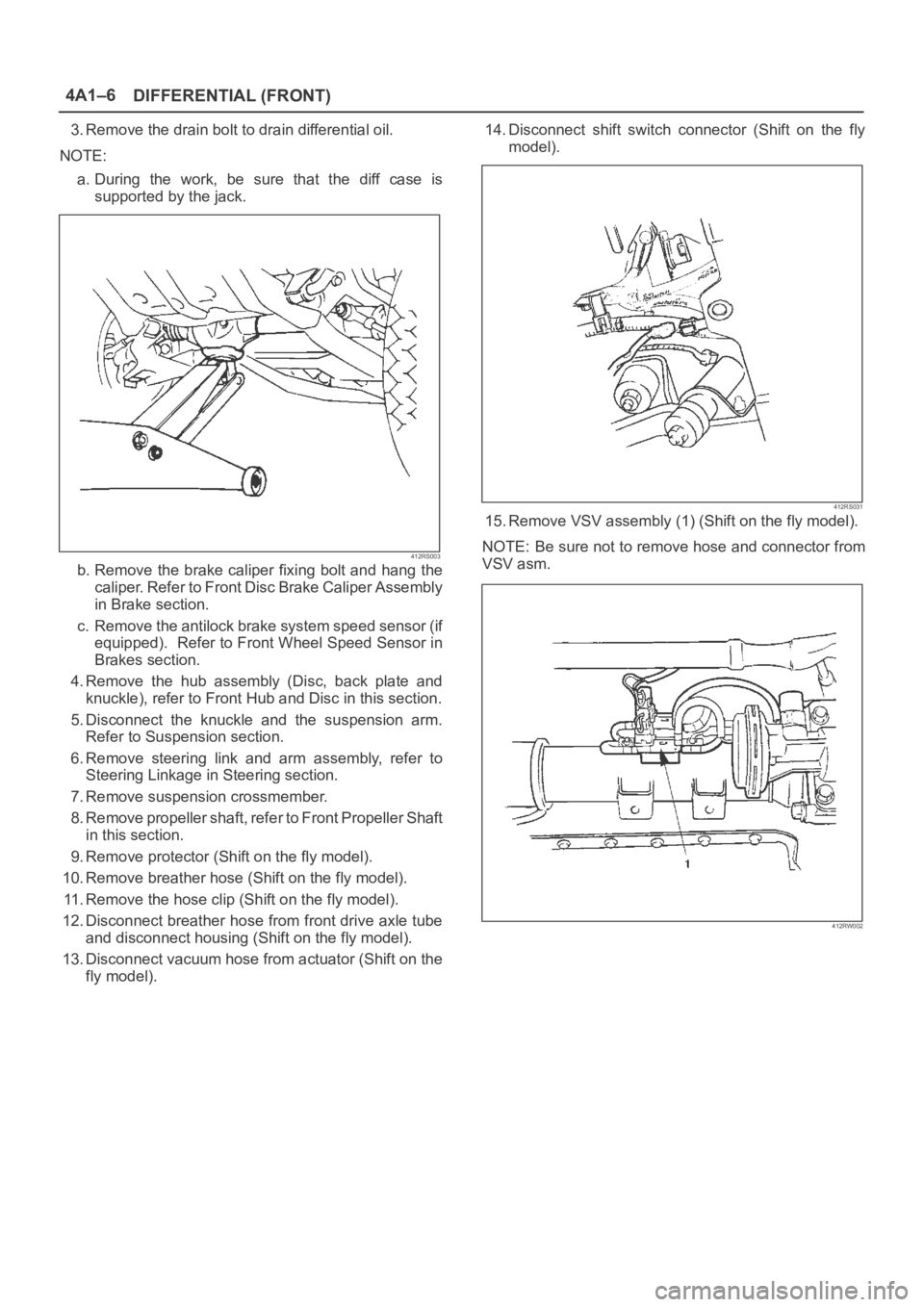
3. Remove the drain bolt to drain differential oil.
NOTE:
a. During the work, be sure that the diff case is
supported by the jack.
412RS003
b. Remove the brake caliper fixing bolt and hang the
caliper. Refer to Front Disc Brake Caliper Assembly
in Brake section.
c. Remove the antilock brake system speed sensor (if
equipped). Refer to Front Wheel Speed Sensor in
Brakes section.
4. Remove the hub assembly (Disc, back plate and
knuckle), refer to Front Hub and Disc in this section.
5. Disconnect the knuckle and the suspension arm.
Refer to Suspension section.
6. Remove steering link and arm assembly, refer to
Steering Linkage in Steering section.
7. Remove suspension crossmember.
8. Remove propeller shaft, refer to Front Propeller Shaft
in this section.
9. Remove protector (Shift on the fly model).
10. Remove breather hose (Shift on the fly model).
11. Remove the hose clip (Shift on the fly model).
12. Disconnect breather hose from front drive axle tube
and disconnect housing (Shift on the fly model).
13. Disconnect vacuum hose from actuator (Shift on the
fly model).14. Disconnect shift switch connector (Shift on the fly
model).
412RS031
15. Remove VSV assembly (1) (Shift on the fly model).
NOTE: Be sure not to remove hose and connector from
VSV asm.
412RW002
Page 471 of 6000
4A2A–4
DIFFERENTIAL (REAR 220mm)
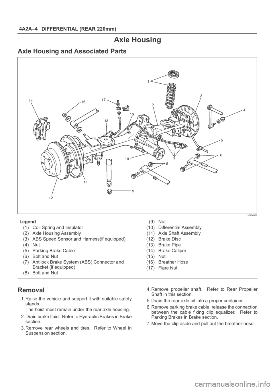
Axle Housing
Axle Housing and Associated Parts
420RW022
Legend
(1) Coil Spring and Insulator
(2) Axle Housing Assembly
(3) ABS Speed Sensor and Harness(if equipped)
(4) Nut
(5) Parking Brake Cable
(6) Bolt and Nut
(7) Antilock Brake System (ABS) Connector and
Bracket (if equipped)
(8) Bolt and Nut(9) Nut
(10) Differential Assembly
(11) Axle Shaft Assembly
(12) Brake Disc
(13) Brake Pipe
(14) Brake Caliper
(15) Nut
(16) Breather Hose
(17) Flare Nut
Removal
1. Raise the vehicle and support it with suitable safety
stands.
The hoist must remain under the rear axle housing.
2. Drain brake fluid. Refer to Hydraulic Brakes in Brake
section.
3. Remove rear wheels and tires. Refer to Wheel in
Suspension section.4. Remove propeller shaft. Refer to Rear Propeller
Shaft in this section.
5. Drain the rear axle oil into a proper container.
6. Remove parking brake cable, release the connection
between the cable fixing clip equalizer. Refer to
Parking Brakes in Brake section.
7. Move the clip aside and pull out the breather hose.
Page 475 of 6000
4A2A–8
DIFFERENTIAL (REAR 220mm)
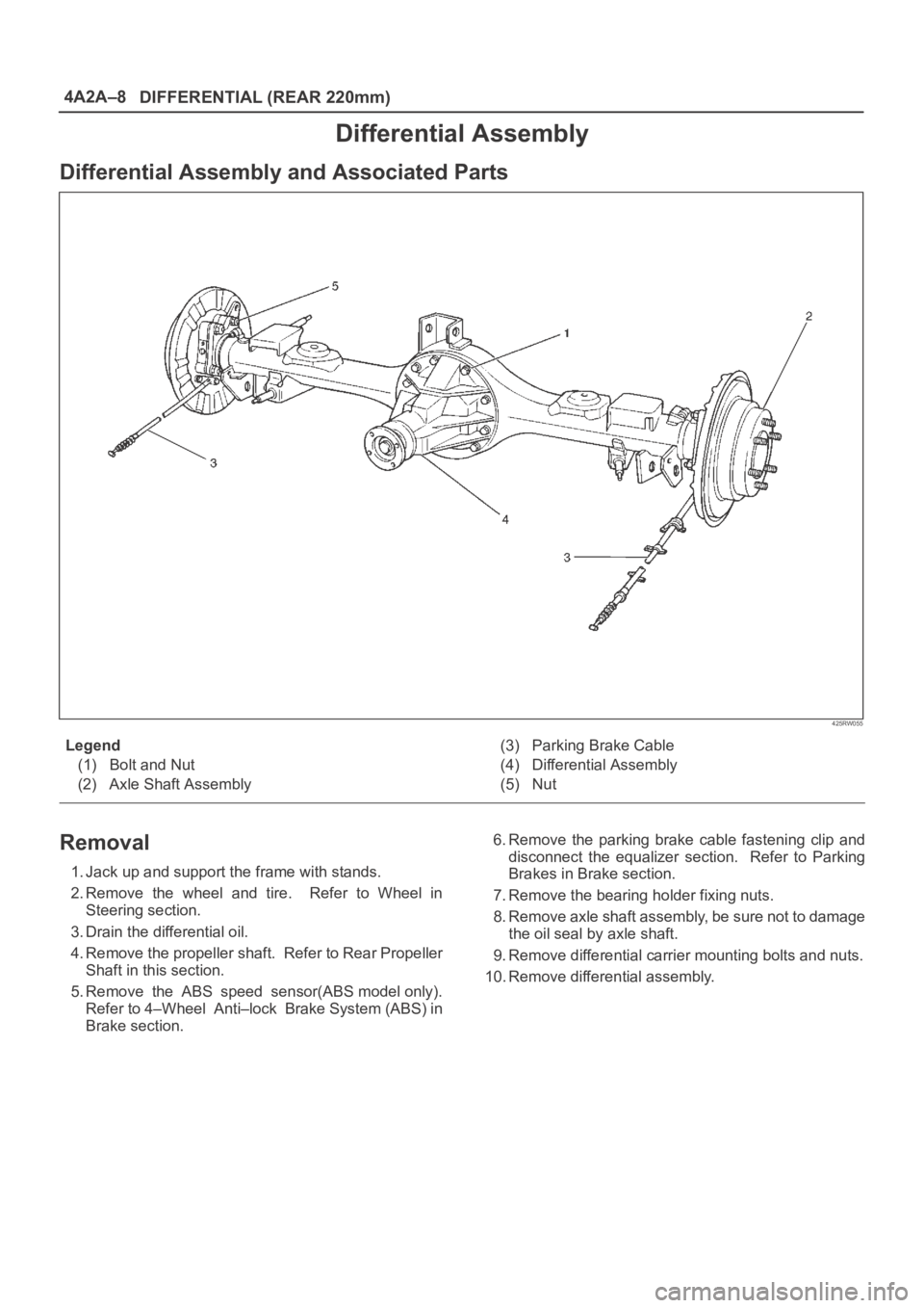
Differential Assembly
Differential Assembly and Associated Parts
425RW055
Legend
(1) Bolt and Nut
(2) Axle Shaft Assembly(3) Parking Brake Cable
(4) Differential Assembly
(5) Nut
Removal
1. Jack up and support the frame with stands.
2. Remove the wheel and tire. Refer to Wheel in
Steering section.
3. Drain the differential oil.
4. Remove the propeller shaft. Refer to Rear Propeller
Shaft in this section.
5. Remove the ABS speed sensor(ABS model only).
Refer to 4–Wheel Anti–lock Brake System (ABS) in
Brake section.6. Remove the parking brake cable fastening clip and
disconnect the equalizer section. Refer to Parking
Brakes in Brake section.
7. Remove the bearing holder fixing nuts.
8. Remove axle shaft assembly, be sure not to damage
the oil seal by axle shaft.
9. Remove differential carrier mounting bolts and nuts.
10. Remove differential assembly.
Page 507 of 6000
4A2B–4DIFFERENTIAL (REAR 244mm)
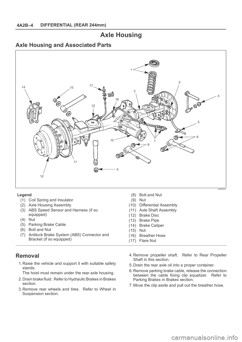
Axle Housing
Axle Housing and Associated Parts
420RW001
Legend
(1) Coil Spring and Insulator
(2) Axle Housing Assembly
(3) ABS Speed Sensor and Harness (if so
equipped)
(4) Nut
(5) Parking Brake Cable
(6) Bolt and Nut
(7) Antilock Brake System (ABS) Connector and
Bracket (if so equipped)(8) Bolt and Nut
(9) Nut
(10) Differential Assembly
(11) Axle Shaft Assembly
(12) Brake Disc
(13) Brake Pipe
(14) Brake Caliper
(15) Nut
(16) Breather Hose
(17) Flare Nut
Removal
1. Raise the vehicle and support it with suitable safety
stands.
The hoist must remain under the rear axle housing.
2. Drain brake fluid. Refer to Hydraulic Brakes in Brakes
section.
3. Remove rear wheels and tires. Refer to Wheel in
Suspension section.4. Remove propeller shaft. Refer to Rear Propeller
Shaft in this section.
5. Drain the rear axle oil into a proper container.
6. Remove parking brake cable, release the connection
between the cable fixing clip equalizer. Refer to
Parking Brakes in Brakes section.
7. Move the clip aside and pull out the breather hose.
Page 511 of 6000
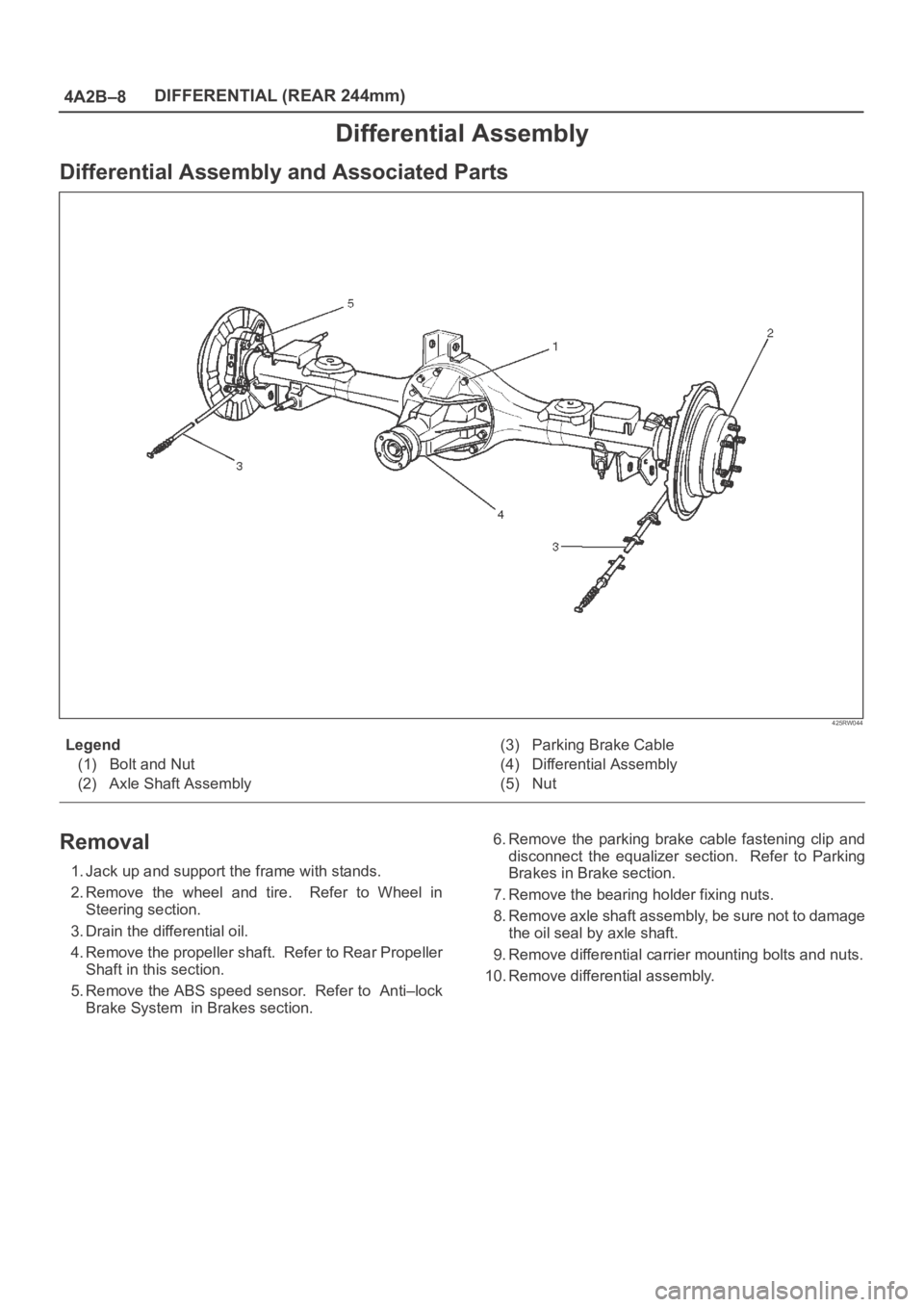
4A2B–8DIFFERENTIAL (REAR 244mm)
Differential Assembly
Differential Assembly and Associated Parts
425RW044
Legend
(1) Bolt and Nut
(2) Axle Shaft Assembly(3) Parking Brake Cable
(4) Differential Assembly
(5) Nut
Removal
1. Jack up and support the frame with stands.
2. Remove the wheel and tire. Refer to Wheel in
Steering section.
3. Drain the differential oil.
4. Remove the propeller shaft. Refer to Rear Propeller
Shaft in this section.
5. Remove the ABS speed sensor. Refer to Anti–lock
Brake System in Brakes section.6. Remove the parking brake cable fastening clip and
disconnect the equalizer section. Refer to Parking
Brakes in Brake section.
7. Remove the bearing holder fixing nuts.
8. Remove axle shaft assembly, be sure not to damage
the oil seal by axle shaft.
9. Remove differential carrier mounting bolts and nuts.
10. Remove differential assembly.
Page 694 of 6000

4C–28
DRIVE SHAFT SYSTEM
Shift On The Fly System
Shift On The Fly System and Associated Parts
412RW004
Legend
(1) Filler Plug
(2) Bolt
(3) Oil Seal
(4) Snap Ring(External)
(5) Inner Shaft Bearing
(6) Snap Ring(Internal)
(7) Inner Shaft(8) Needle Bearing
(9) Clutch Gear
(10) Sleeve
(11) Housing
(12) Front Axle Drive Shaft (LH side)with Bracket
(13) Bolt
(14) Actuator Assembly
(15) Bolt
Disassembly
1. Remove filler plug and gasket, drain oil.
2. Loosen mounting bracket fitting bolts and remove
front axle drive shaft from front axle case.3. Remove Actuator Assembly and draw out actuator
ASM.
4. Remove housing.
5. Remove sleeve.
6. Remove clutch gear.