1998 OPEL FRONTERA drain bolt
[x] Cancel search: drain boltPage 1489 of 6000
6G–10
ENGINE LUBRICATION
Oil Pump
Removal
1. Disconnect battery ground cable.
2. Drain engine oil.
3. Remove crankcase assembly.
Refer to removal procedure for Oil Pan and
Crankcase in this manual.
4. Remove crankshaft pulley.
Refer to removal procedure for Crankshaft Pulley in
this manual.
5. Remove timing belt.
Refer to removal procedure for Timing Belt in this
manual.
6. Remove timing pulley from crankshaft.
7. Remove four fixing bolts from oil filter assembly.
8. Remove oil strainer fixing bolts, remove oil strainer
assembly with O-ring.
9. Remove three bolts from oil pipe and O-ring.
10. Remove eight oil pump fixing bolts, then oil pump
assembly.
11. Remove sealant from mounting surface of oil pump
assembly, cylinder block and take care not to damage
mounting surfaces of oil pump and cylinder block.
Installation
1. Install oil pump assembly
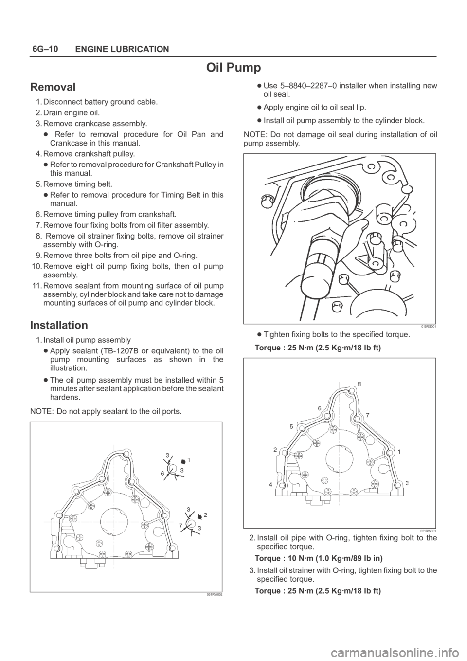
Apply sealant (TB-1207B or equivalent) to the oil
pump mounting surfaces as shown in the
illustration.
The oil pump assembly must be installed within 5
minutes after sealant application before the sealant
hardens.
NOTE: Do not apply sealant to the oil ports.
051RW002
Use 5–8840–2287–0 installer when installing new
oil seal.
Apply engine oil to oil seal lip.
Install oil pump assembly to the cylinder block.
NOTE: Do not damage oil seal during installation of oil
pump assembly.
015RS001
Tighten fixing bolts to the specified torque.
Torque : 25 Nꞏm (2.5 Kgꞏm/18 lb ft)
051RW001
2. Install oil pipe with O-ring, tighten fixing bolt to the
specified torque.
Torque : 10 Nꞏm (1.0 Kgꞏm/89 lb in)
3. Install oil strainer with O-ring, tighten fixing bolt to the
specified torque.
Torque : 25 Nꞏm (2.5 Kgꞏm/18 lb ft)
Page 1761 of 6000
6A – 28 ENGINE MECHANICAL
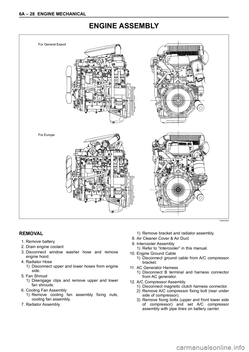
ENGINE ASSEMBLY
For General Export
For Europe
F06R200004
REMOVAL
1. Remove battery.
2. Drain engine coolant
3. Disconnect window washer hose and remove
engine hood.
4. Radiator Hose
1) Disconnect upper and lower hoses from engine
side.
5. Fan Shroud
1) Disengage clips and remove upper and lower
fan shrouds.
6. Cooling Fan Assembly
1) Remove cooling fan assembly fixing nuts,
cooling fan assembly.
7. Radiator Assembly1) Remove bracket and radiator assembly.
8. Air Cleaner Cover & Air Duct
9. Intercooler Assembly
1) Refer to “Intercooler” in this manual.
10. Engine Ground Cable
1) Disconnect ground cable from A/C compressor
bracket.
11. AC Generator Harness
1) Disconnect B terminal and harness connector
from AC generator.
12. A/C Compressor Assembly
1) Disconnect magnetic clutch harness connector.
2) Remove A/C compressor fixing bolt (rear under
side of compressor).
3) Remove fixing bolts (upper and front lower side
of compressor) and set A/C compressor
assembly with pipe lines on battery carrier.
Page 1768 of 6000

ENGINE MECHANICAL 6A – 35
INTAKE MANIFOLD
REMOVAL
1. Drain engine coolant and disconnect water hose
from thermostat hosing.
2. Remove intercooler assembly
Refer to “Intercooler” in this manual.
3. Remove bracket bolt of oil level gauge guide tube.
4. Remove PCV Hose.
5. Remove hoses from EGR, EGR vacuum sensor
and inlet/outlet of heater.
6. Disconnect harness connector form MAP sensor,
EGR vacuum sensor, ETC sensor, water
temperature unit, IAT sensor and EVRV.
7. Remove high pressure oil pipe.
8. Remove the two way valve.
9. Remove fuel pipe from between intake manifold
and high pressure oil pump.
10. Remove fixing bolts and nuts on the intake
manifold, then remove the intake manifold
assembly.
INSTALLATION
1. Install the intake manifold, tighten bolts and nuts to
the specified torque.
Torque : 20 Nꞏm (2.0 kgꞏm/14.5 lb ft) for bolt and nut
2. Install the fuel pipe and tighten to the specified
torque.To r q u e :
M16 bolt (apply engine oil) 4 Nꞏm (0.4 kgꞏm/2.9
lb ft)
Cap nut (M10) 13Nꞏm (1.3 kgꞏm/9.4 lb ft)
Fuel pipe (M10 apply engine oil) 14 Nꞏm (1.4
kgꞏm/10 lb ft)
3. Install two way valve.
Torque : 20 Nꞏm (2.0 kgꞏm/14.5 lb ft)
4. Fill with about 300 cc of engine oil from the high
pressure oil pipe installation port of the oil rail using
an oil filler. If assembled without filling the oil rail
with oil, the time for starting the engine will be
longer.
5. Install the high pressure oil pipe immediately and
tighten the sleeve nut to the specified torque.
Torque : 80 Nꞏm (8 kgꞏm/57.9 lb ft)
6. Reconnect harness connector to MAP sensor, EGR
vacuum sensor, ETC sensor, Water temperature
unit, IAT sensor and EVRV.
7. Connect the hoses to EGR valve, EGR vacuum
sensor, and water inlet/outlet pipe for heater.
8. Connect PCV hose.
9. Install the oil level gauge guide tube and tighten
bracket bolt.
10. Install the intercooler assembly.
Refer to “Intercooler” in this manual.
11. Connect the hose to the thermostat housing and fill
with engine coolant.
For Europe
2
1
3
3 1 42
025R200005
Legend
(1) Intake Manifold
(2) Throttle Valve Assembly
(3) EGR Valve
(4) Gasket
Page 1772 of 6000
ENGINE MECHANICAL 6A – 39
REMOVAL
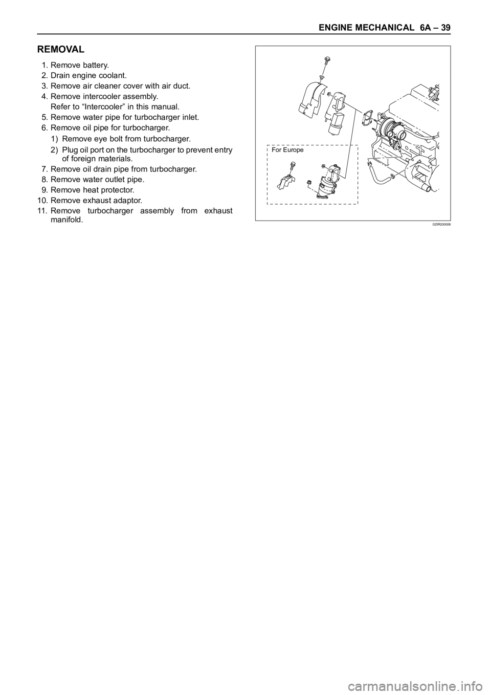
1. Remove battery.
2. Drain engine coolant.
3. Remove air cleaner cover with air duct.
4. Remove intercooler assembly.
Refer to “Intercooler” in this manual.
5. Remove water pipe for turbocharger inlet.
6. Remove oil pipe for turbocharger.
1) Remove eye bolt from turbocharger.
2) Plug oil port on the turbocharger to prevent entry
of foreign materials.
7. Remove oil drain pipe from turbocharger.
8. Remove water outlet pipe.
9. Remove heat protector.
10. Remove exhaust adaptor.
11. Remove turbocharger assembly from exhaust
manifold.
For Europe
025R200006
Page 1773 of 6000
6A – 40 ENGINE MECHANICAL
INSTALLATION
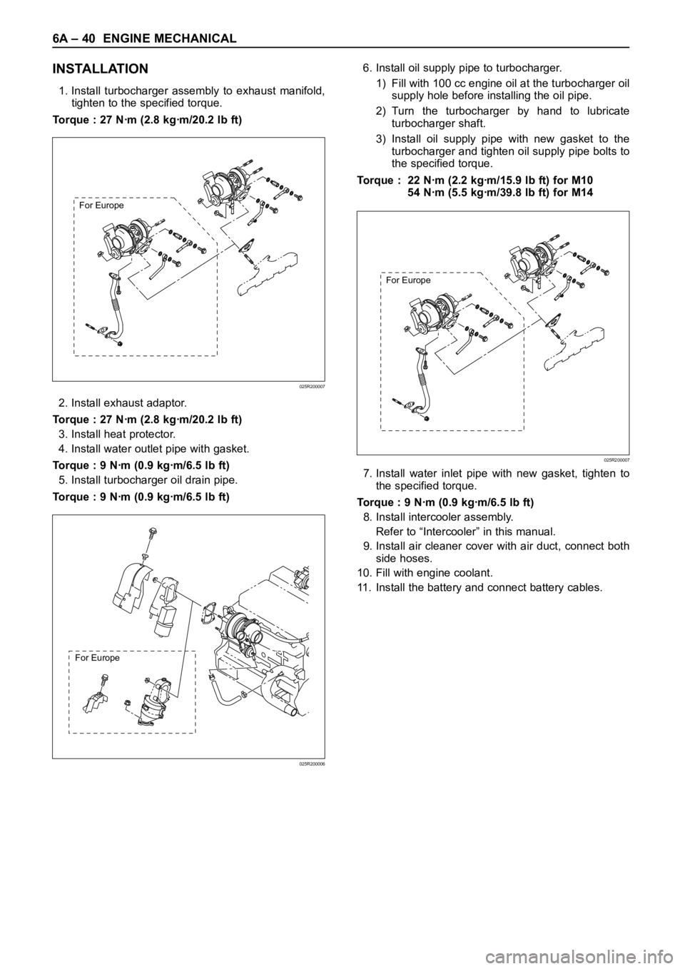
1. Install turbocharger assembly to exhaust manifold,
tighten to the specified torque.
Torque : 27 Nꞏm (2.8 kgꞏm/20.2 lb ft)
2. Install exhaust adaptor.
Torque : 27 Nꞏm (2.8 kgꞏm/20.2 lb ft)
3. Install heat protector.
4. Install water outlet pipe with gasket.
Torque : 9 Nꞏm (0.9 kgꞏm/6.5 lb ft)
5. Install turbocharger oil drain pipe.
Torque : 9 Nꞏm (0.9 kgꞏm/6.5 lb ft)6. Install oil supply pipe to turbocharger.
1) Fill with 100 cc engine oil at the turbocharger oil
supply hole before installing the oil pipe.
2) Turn the turbocharger by hand to lubricate
turbocharger shaft.
3) Install oil supply pipe with new gasket to the
turbocharger and tighten oil supply pipe bolts to
the specified torque.
Torque : 22 Nꞏm (2.2 kgꞏm/15.9 lb ft) for M10
54 Nꞏm (5.5 kgꞏm/39.8 lb ft) for M14
7. Install water inlet pipe with new gasket, tighten to
the specified torque.
Torque : 9 Nꞏm (0.9 kgꞏm/6.5 lb ft)
8. Install intercooler assembly.
Refer to “Intercooler” in this manual.
9. Install air cleaner cover with air duct, connect both
side hoses.
10. Fill with engine coolant.
11. Install the battery and connect battery cables.
For Europe
025R200007
For Europe
025R200007
For Europe
025R200006
Page 1781 of 6000
6A – 48 ENGINE MECHANICAL
DISASSEMBLY
1. Injector clamp
2. Injector assembly
3. Oil rail assembly
4. Camshaft bracket
5. Camshaft
6. Oil seal
7. Plug
NOTE: Before starting disassembly above, drain oil
from oil rail to prevent oil from entering the cylinder.
REASSEMBLY
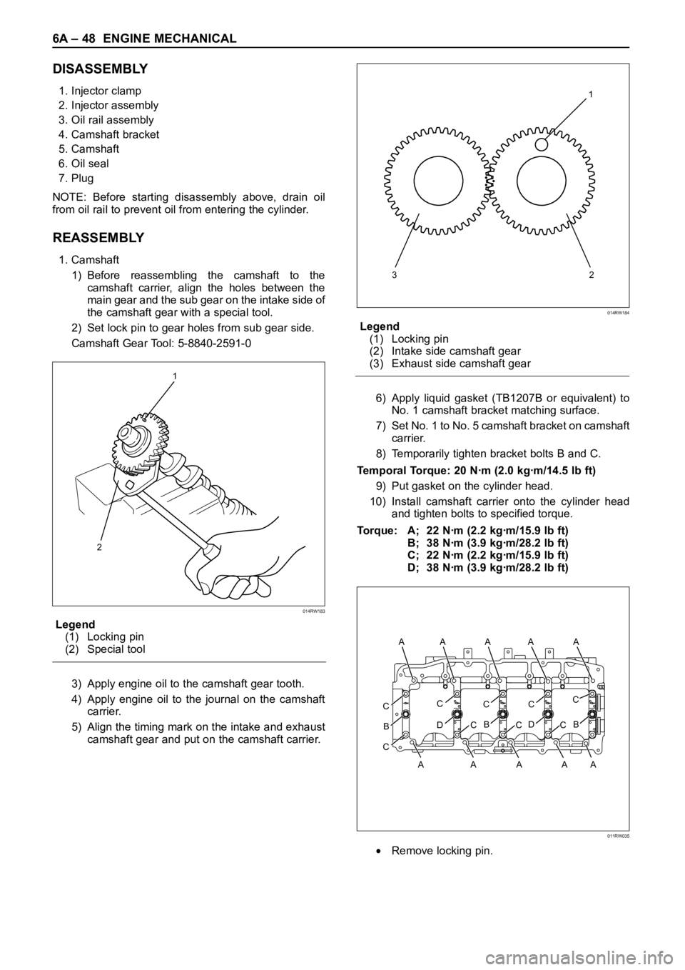
1. Camshaft
1) Before reassembling the camshaft to the
camshaft carrier, align the holes between the
main gear and the sub gear on the intake side of
the camshaft gear with a special tool.
2) Set lock pin to gear holes from sub gear side.
Camshaft Gear Tool: 5-8840-2591-0
Legend
(1) Locking pin
(2) Special tool
3) Apply engine oil to the camshaft gear tooth.
4) Apply engine oil to the journal on the camshaft
carrier.
5) Align the timing mark on the intake and exhaust
camshaft gear and put on the camshaft carrier.Legend
(1) Locking pin
(2) Intake side camshaft gear
(3) Exhaust side camshaft gear
6) Apply liquid gasket (TB1207B or equivalent) to
No. 1 camshaft bracket matching surface.
7) Set No. 1 to No. 5 camshaft bracket on camshaft
carrier.
8) Temporarily tighten bracket bolts B and C.
Temporal Torque: 20 Nꞏm (2.0 kgꞏm/14.5 lb ft)
9) Put gasket on the cylinder head.
10) Install camshaft carrier onto the cylinder head
and tighten bolts to specified torque.
Torque: A; 22 Nꞏm (2.2 kgꞏm/15.9 lb ft)
B; 38 Nꞏm (3.9 kgꞏm/28.2 lb ft)
C; 22 Nꞏm (2.2 kgꞏm/15.9 lb ft)
D; 38 Nꞏm (3.9 kgꞏm/28.2 lb ft)
Remove locking pin.
1
2
014RW183
321
014RW184
CC
D
B
CC
B
CC
D
CC
B
C
A AA A A A
AAAA
011RW035
Page 1800 of 6000
ENGINE MECHANICAL 6A – 67
VALVE CLEARANCE ADJUSTMENT
NOTE:
1. Valve clearance should be inspected and adjusted
while the engine is cool.
2. The tightening of the camshaft bearing cap and
camshaft carrier assembly should be checked
before inspecting and adjusting valve clearance.
INSPECTION
1. Remove cylinder head noise insulator cover and
cylinder head cover.
Refer to “Cylinder Head” in this manual.
2. Disconnect all harness connecters of the injector
and remove harness assembly.
3. Drain oil from oil rail assembly.
4. Remove injector clamp nuts and fixing bolts to take
out injector assembly.
5. Loosen oil rail bolts, remove oil rail assembly.
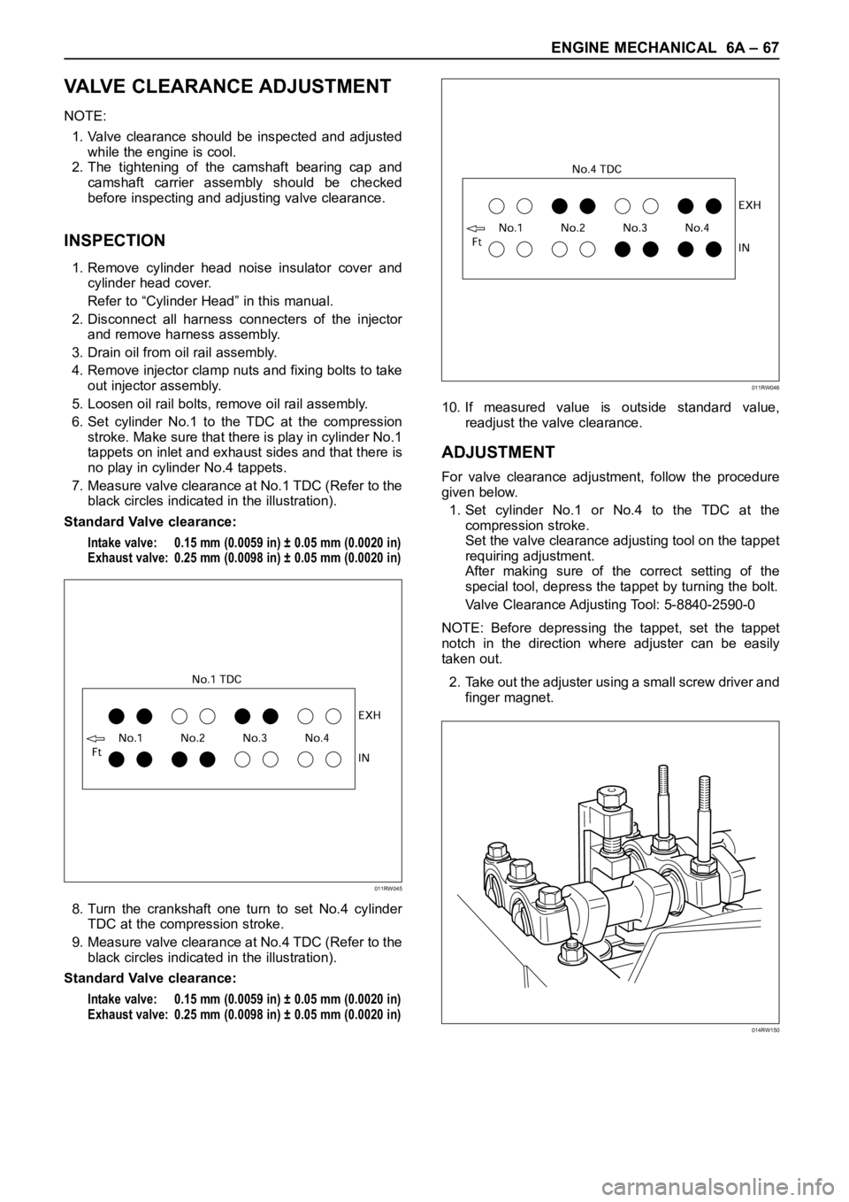
6. Set cylinder No.1 to the TDC at the compression
stroke. Make sure that there is play in cylinder No.1
tappets on inlet and exhaust sides and that there is
no play in cylinder No.4 tappets.
7. Measure valve clearance at No.1 TDC (Refer to the
black circles indicated in the illustration).
Standard Valve clearance:
Intake valve: 0.15 mm (0.0059 in) ± 0.05 mm (0.0020 in)
Exhaust valve: 0.25 mm (0.0098 in) ± 0.05 mm (0.0020 in)
8. Turn the crankshaft one turn to set No.4 cylinder
TDC at the compression stroke.
9. Measure valve clearance at No.4 TDC (Refer to the
black circles indicated in the illustration).
Standard Valve clearance:
Intake valve: 0.15 mm (0.0059 in) ± 0.05 mm (0.0020 in)
Exhaust valve: 0.25 mm (0.0098 in) ± 0.05 mm (0.0020 in)
10. If measured value is outside standard value,
readjust the valve clearance.
ADJUSTMENT
For valve clearance adjustment, follow the procedure
given below.
1. Set cylinder No.1 or No.4 to the TDC at the
compression stroke.
Set the valve clearance adjusting tool on the tappet
requiring adjustment.
After making sure of the correct setting of the
special tool, depress the tappet by turning the bolt.
Valve Clearance Adjusting Tool: 5-8840-2590-0
NOTE: Before depressing the tappet, set the tappet
notch in the direction where adjuster can be easily
taken out.
2. Take out the adjuster using a small screw driver and
finger magnet.
011RW045
011RW046
014RW150
Page 1802 of 6000
ENGINE MECHANICAL 6A – 69
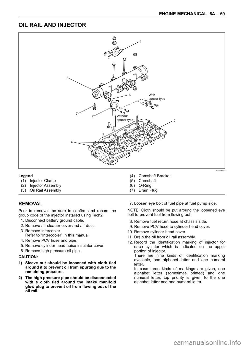
OIL RAIL AND INJECTOR
REMOVAL
Prior to removal, be sure to confirm and record the
group code of the injector installed using Tech2.
1. Disconnect battery ground cable.
2. Remove air cleaner cover and air duct.
3. Remove intercooler.
Refer to “Intercooler” in this manual.
4. Remove PCV hose and pipe.
5. Remove cylinder head noise insulator cover.
6. Remove high pressure oil pipe.
CAUTION:
1) Sleeve nut should be loosened with cloth tied
around it to prevent oil from spurting due to the
remaining pressure.
2) The high pressure pipe should be disconnected
with a cloth tied around the intake manifold
glow plug to prevent oil from flowing out of the
oil rail.7. Loosen eye bolt of fuel pipe at fuel pump side.
NOTE: Cloth should be put around the loosened eye
bolt to prevent fuel from flowing out.
8. Remove fuel return hose at chassis side.
9. Remove PCV hose to cylinder head cover.
10. Remove cylinder head cover.
11. Drain the oil from oil rail assembly.
12. Record the identification marking of injector for
each cylinder which is indicated on the upper
portion of injector.
There are nine kinds of identification marking
available, one alphabet letter and one numeral
letter.
In case three kinds of markings are given, one
alphabet letter (sometimes printed) and one
numeral letter, top priority is given to the one
alphabet letter and one numeral letter.
1
6
27
3
5
4
With
spacer type
Without
spacer type
012R200005
Legend
(1) Injector Clamp
(2) Injector Assembly
(3) Oil Rail Assembly(4) Camshaft Bracket
(5) Camshaft
(6) O-Ring
(7) Drain Plug