Page 3978 of 6000
DIFFERENTIAL (REAR 220mm)
4A2A–9
6. Install snap ring.
7. Install axle shaft assembly.
NOTE: Be sure not to damage the oil seal.
8. Tighten the bearing holder mounting nut to the
specified torque.
Torque: 74Nꞏm (54 Ib ft)
9. Fix the parking brake cable mounting bolt (Behind the
back plate).10. Install parking brake assembly, refer to Parking
Brakes in Brake section.
11. Install antilock brake system sensor.
12. Install brake disc.
13. Install brake caliper, refer to Disk Brakes in Brake
section.
Pinion Oil Seal
Pinion Oil Seal and Associated Parts
425RW054
Legend
(1) Flange Nut and Washer
(2) Flange(3) Oil Seal
(4) Outer Bearing
(5) Collapsible Spacer
Removal
1.Remove the rear propeller shaft. Refer to Rear
Propeller Shaft in this section.
2. Drain the rear axle oil.
Page 3980 of 6000
DIFFERENTIAL (REAR 220mm)
4A2A–11
Differential Assembly
Differential Assembly and Associated Parts
425RW055
Legend
(1) Bolt and Nut
(2) Axle Shaft Assembly(3) Parking Brake Cable
(4) Differential Assembly
(5) Nut
Removal
1. Jack up and support the frame with stands.
2. Remove the wheel and tire. Refer to Wheel in
Steering section.
3. Drain the differential oil.
4. Remove the propeller shaft. Refer to Rear Propeller
Shaft in this section.
5. Remove the ABS speed sensor(ABS model only).
Refer to 4–Wheel Anti–lock Brake System (ABS) in
Brake section.6. Remove the parking brake cable fastening clip and
disconnect the equalizer section. Refer to Parking
Brakes in Brake section.
7. Remove the bearing holder fixing nuts.
8. Remove axle shaft assembly, be sure not to damage
the oil seal by axle shaft.
9. Remove differential carrier mounting bolts and nuts.
10. Remove differential assembly.
Page 4012 of 6000

DIFFERENTIAL (REAR 244mm)
4A2B–5
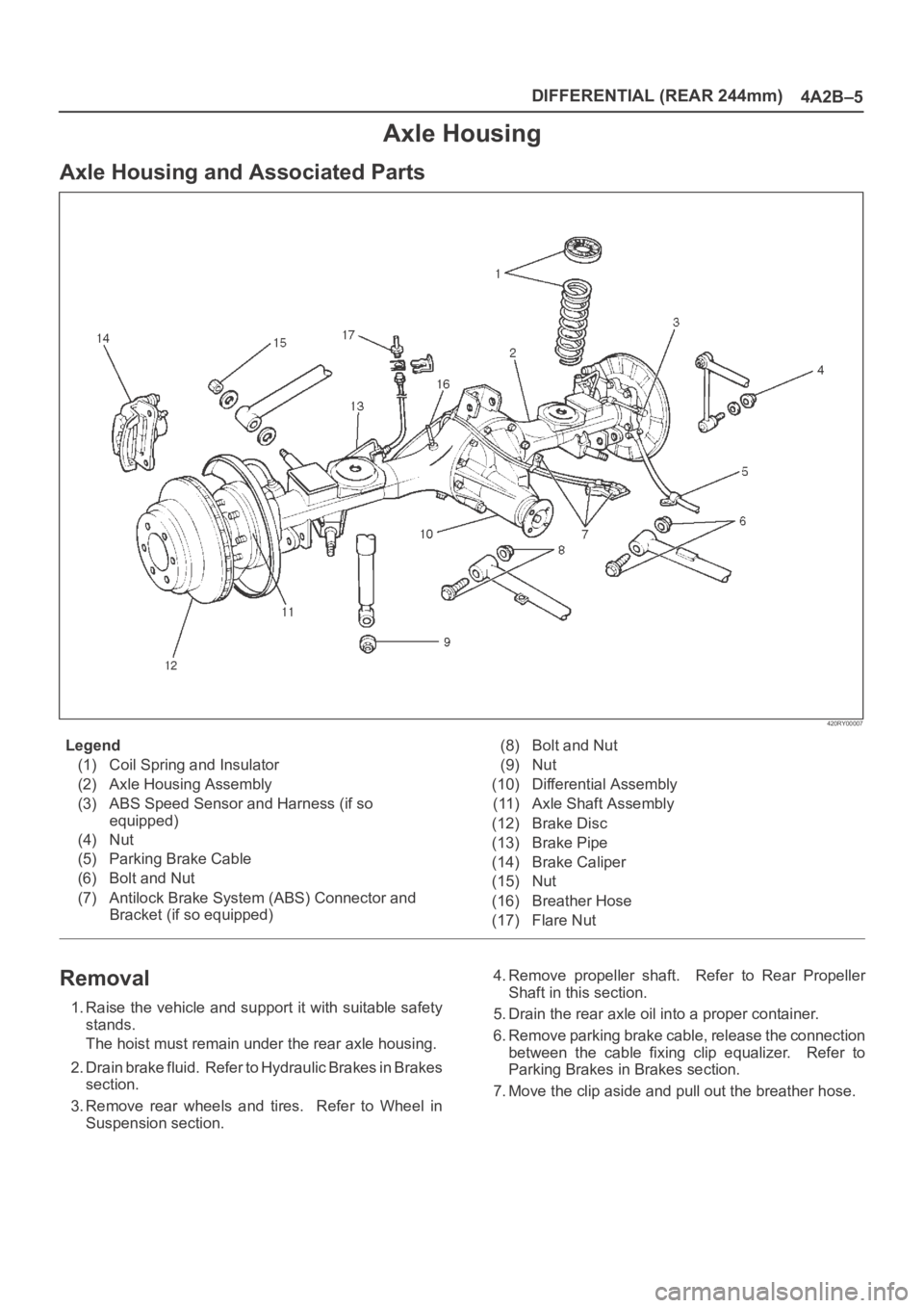
Axle Housing
Axle Housing and Associated Parts
420RY00007
Legend
(1) Coil Spring and Insulator
(2) Axle Housing Assembly
(3) ABS Speed Sensor and Harness (if so
equipped)
(4) Nut
(5) Parking Brake Cable
(6) Bolt and Nut
(7) Antilock Brake System (ABS) Connector and
Bracket (if so equipped)(8) Bolt and Nut
(9) Nut
(10) Differential Assembly
(11) Axle Shaft Assembly
(12) Brake Disc
(13) Brake Pipe
(14) Brake Caliper
(15) Nut
(16) Breather Hose
(17) Flare Nut
Removal
1. Raise the vehicle and support it with suitable safety
stands.
The hoist must remain under the rear axle housing.
2. Drain brake fluid. Refer to Hydraulic Brakes in Brakes
section.
3. Remove rear wheels and tires. Refer to Wheel in
Suspension section.4. Remove propeller shaft. Refer to Rear Propeller
Shaft in this section.
5. Drain the rear axle oil into a proper container.
6. Remove parking brake cable, release the connection
between the cable fixing clip equalizer. Refer to
Parking Brakes in Brakes section.
7. Move the clip aside and pull out the breather hose.
Page 4017 of 6000
4A2B–10DIFFERENTIAL (REAR 244mm)
6. Install snap ring.
7. Install axle shaft assembly.
NOTE: Be sure not to damage the oil seal.
8. Tighten the bearing holder mounting nut to the
specified torque.
Torque: 74Nꞏm (54 Ib ft)
9. Fix the parking brake cable mounting bolt (Behind the
back plate).10. Install parking brake assembly, refer to Parking
Brakes in Brake section.
11. Install antilock brake system sensor.
12. Install brake disc.
13. Install brake caliper, refer to Disk Brakes in Brake
section.
Pinion Oil Seal
Pinion Oil Seal and Associated Parts
425RY00010
Legend
(1) Flange Nut and Washer
(2) Flange(3) Oil Seal
(4) Outer Bearing
(5) Collapsible Spacer
Removal
1.Remove the rear propeller shaft. Refer to Rear
Propeller Shaft in this section.
2. Drain the rear axle oil.
Page 4019 of 6000
4A2B–12DIFFERENTIAL (REAR 244mm)
Differential Assembly
Differential Assembly and Associated Parts
425RY00016
Legend
(1) Bolt and Nut
(2) Axle Shaft Assembly(3) Parking Brake Cable
(4) Differential Assembly
(5) Nut
Removal
1. Jack up and support the frame with stands.
2. Remove the wheel and tire. Refer to Wheel in
Steering section.
3. Drain the differential oil.
4. Remove the propeller shaft. Refer to Rear Propeller
Shaft in this section.
5. Remove the ABS speed sensor. Refer to Anti–lock
Brake System in Brakes section.6. Remove the parking brake cable fastening clip and
disconnect the equalizer section. Refer to Parking
Brakes in Brake section.
7. Remove the bearing holder fixing nuts.
8. Remove axle shaft assembly, be sure not to damage
the oil seal by axle shaft.
9. Remove differential carrier mounting bolts and nuts.
10. Remove differential assembly.
Page 4234 of 6000
4C–28
DRIVE SHAFT SYSTEM
Shift On The Fly System
Shift On The Fly System and Associated Parts
412RW004
Legend
(1) Filler Plug
(2) Bolt
(3) Oil Seal
(4) Snap Ring(External)
(5) Inner Shaft Bearing
(6) Snap Ring(Internal)
(7) Inner Shaft(8) Needle Bearing
(9) Clutch Gear
(10) Sleeve
(11) Housing
(12) Front Axle Drive Shaft (LH side)with Bracket
(13) Bolt
(14) Actuator Assembly
(15) Bolt
Disassembly
1. Remove filler plug and gasket, drain oil.
2. Loosen mounting bracket fitting bolts and remove
front axle drive shaft from front axle case.3. Remove Actuator Assembly and draw out actuator
ASM.
4. Remove housing.
5. Remove sleeve.
6. Remove clutch gear.
Page 4270 of 6000

TRANSFER CASE (STANDARD TYPE)
4D1–9
266RW002
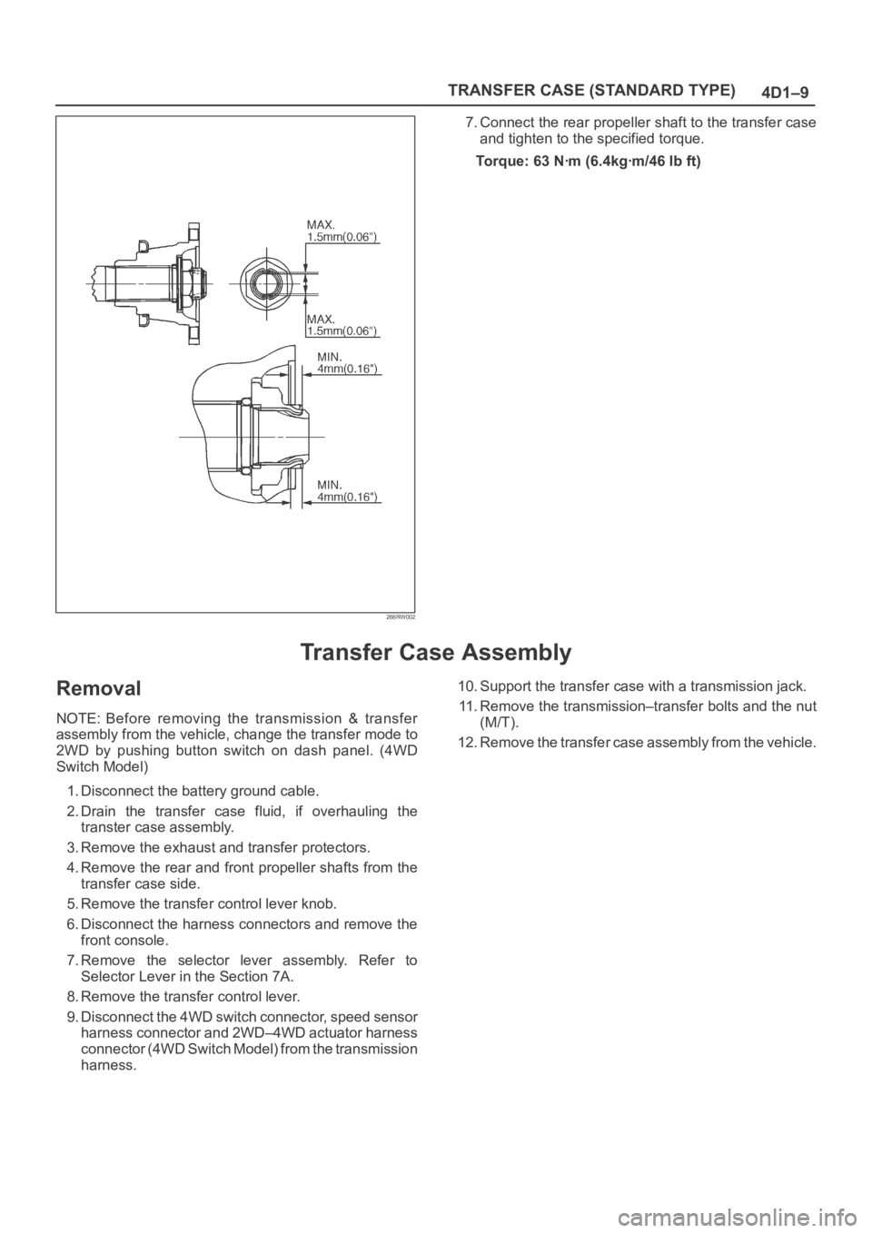
7. Connect the rear propeller shaft to the transfer case
and tighten to the specified torque.
Torque: 63 Nꞏm (6.4kgꞏm/46 lb ft)
Transfer Case Assembly
Removal
NOTE: Before removing the transmission & transfer
assembly from the vehicle, change the transfer mode to
2WD by pushing button switch on dash panel. (4WD
Switch Model)
1. Disconnect the battery ground cable.
2. Drain the transfer case fluid, if overhauling the
transter case assembly.
3. Remove the exhaust and transfer protectors.
4. Remove the rear and front propeller shafts from the
transfer case side.
5. Remove the transfer control lever knob.
6. Disconnect the harness connectors and remove the
front console.
7. Remove the selector lever assembly. Refer to
Selector Lever in the Section 7A.
8. Remove the transfer control lever.
9. Disconnect the 4WD switch connector, speed sensor
harness connector and 2WD–4WD actuator harness
connector (4WD Switch Model) from the transmission
harness.10. Support the transfer case with a transmission jack.
11. Remove the transmission–transfer bolts and the nut
(M/T).
12. Remove the transfer case assembly from the vehicle.
Page 4318 of 6000

4D2–11 TRANSFER CASE (TOD)
2. Tighten the sixteen bolts to the specified torque.
Torque : 31 Nꞏm (3.2 kgꞏm/23 lb ft)
3. Wind the sealing tape around the drain plug thread
and tighten the plug to the specified torque.
Torque : 25 Nꞏm (2.5 kgꞏm/18 lb ft)
4. Mount the offset lever to the transfer shift and install
the spring pin.
261RW016
5. Attach the O-ring and washer to the companion
flange.
NOTE: Securely push the O-ring to the hollow of the
companion flange, and then attach the washer.
6. Use the flange holder 5-8840-0133-0 (J-8614-11) to
tighten the flange nut.
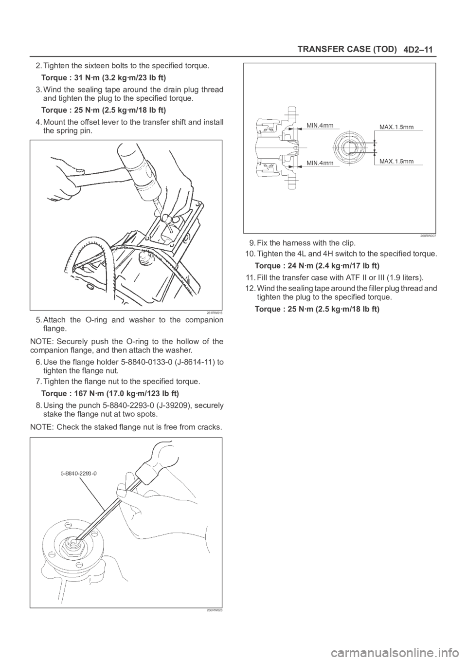
7. Tighten the flange nut to the specified torque.
Torque : 167 Nꞏm (17.0 kgꞏm/123 lb ft)
8. Using the punch 5-8840-2293-0 (J-39209), securely
stake the flange nut at two spots.
NOTE: Check the staked flange nut is free from cracks.
266RW028
260RW007
9. Fix the harness with the clip.
10. Tighten the 4L and 4H switch to the specified torque.
Torque : 24 Nꞏm (2.4 kgꞏm/17 lb ft)
11. Fill the transfer case with ATF II or III (1.9 liters).
12. Wind the sealing tape around the filler plug thread and
tighten the plug to the specified torque.
Torque : 25 Nꞏm (2.5 kgꞏm/18 lb ft)