1998 OPEL FRONTERA park assist
[x] Cancel search: park assistPage 8 of 6000
PAGE BACK PAGE NEXT
THIS MALUAL INCLUDES THE FOLLOWING SECTIONS:
SECTION No. CONTRNTS
5A BRAKE CONTROL SYSTEM
5B ANTI-LOCK BRAKE SYSTEM
5C POWER ASSISTED BRAKE SYSTEM
5D PARKING BRAKES
HOME
5A
5B
5C
5D
Page 811 of 6000
5A–1 BRAKE CONTROL SYSTEM
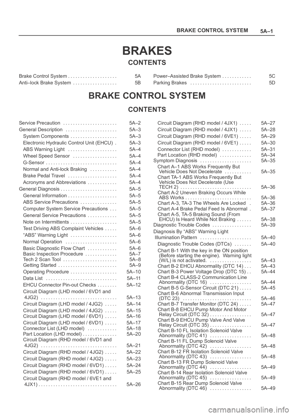
BRAKES
CONTENTS
Brake Control System 5A. . . . . . . . . . . . . . . . . . . .
Anti–lock Brake System 5B. . . . . . . . . . . . . . . . . . Power–Assisted Brake System 5C. . . . . . . . . . . .
Parking Brakes 5D. . . . . . . . . . . . . . . . . . . . . . . . .
BRAKE CONTROL SYSTEM
CONTENTS
Service Precaution 5A–2. . . . . . . . . . . . . . . . . . . . . .
General Description 5A–3. . . . . . . . . . . . . . . . . . . . .
System Components 5A–3. . . . . . . . . . . . . . . . . . .
Electronic Hydraulic Control Unit (EHCU) 5A–3.
ABS Warning Light 5A–4. . . . . . . . . . . . . . . . . . . .
Wheel Speed Sensor 5A–4. . . . . . . . . . . . . . . . . .
G-Sensor 5A–4. . . . . . . . . . . . . . . . . . . . . . . . . . . . .
Normal and Anti-lock Braking 5A–4. . . . . . . . . . .
Brake Pedal Travel 5A–4. . . . . . . . . . . . . . . . . . . .
Acronyms and Abbreviations 5A–4. . . . . . . . . . . .
General Diagnosis 5A–5. . . . . . . . . . . . . . . . . . . . . . .
General Information 5A–5. . . . . . . . . . . . . . . . . . . .
ABS Service Precautions 5A–5. . . . . . . . . . . . . . .
Computer System Service Precautions 5A–5. . .
General Service Precautions 5A–5. . . . . . . . . . . .
Note on Intermittents 5A–5. . . . . . . . . . . . . . . . . . .
Test Driving ABS Complaint Vehicles 5A–6. . . . .
“ABS” Warning Light 5A–6. . . . . . . . . . . . . . . . . . .
Normal Operation 5A–6. . . . . . . . . . . . . . . . . . . . .
Basic Diagnostic Flow Chart 5A–6. . . . . . . . . . . .
Basic Inspection Procedure 5A–7. . . . . . . . . . . . .
Tech 2 Scan Tool 5A–8. . . . . . . . . . . . . . . . . . . . . .
Getting Started 5A–9. . . . . . . . . . . . . . . . . . . . . . . .
Operating Procedure 5A–10. . . . . . . . . . . . . . . . . . .
Data List 5A–11. . . . . . . . . . . . . . . . . . . . . . . . . . . . .
EHCU Connector Pin-out Checks 5A–12. . . . . . . .
Circuit Diagram (LHD model / 6VD1 and
4JG2) 5A–13. . . . . . . . . . . . . . . . . . . . . . . . . . . . . . .
Circuit Diagram (LHD model / 4JG2) 5A–14. . . . .
Circuit Diagram (LHD model / 4JG2) 5A–15. . . . .
Circuit Diagram (LHD model / 6VD1) 5A–16. . . . .
Circuit Diagram (LHD model / 6VD1) 5A–17. . . . .
Connector List (LHD model) 5A–18. . . . . . . . . . . .
Part Location (LHD model) 5A–20. . . . . . . . . . . . . .
Circuit Diagram (RHD model / 6VD1 and
4JG2) 5A–21. . . . . . . . . . . . . . . . . . . . . . . . . . . . . . .
Circuit Diagram (RHD model / 4JG2) 5A–22. . . . .
Circuit Diagram (RHD model / 4JG2) 5A–23. . . . .
Circuit Diagram (RHD model / 6VD1) 5A–24. . . . .
Circuit Diagram (RHD model / 6VD1) 5A–25. . . . .
Circuit Diagram (RHD model / 6VE1 and
4JX1) 5A–26. . . . . . . . . . . . . . . . . . . . . . . . . . . . . . . . Circuit Diagram (RHD model / 4JX1) 5A–27. . . . .
Circuit Diagram (RHD model / 4JX1) 5A–28. . . . .
Circuit Diagram (RHD model / 6VE1) 5A–29. . . . .
Circuit Diagram (RHD model / 6VE1) 5A–30. . . . .
Connector List (RHD model) 5A–31. . . . . . . . . . . .
Part Location (RHD model) 5A–34. . . . . . . . . . . . .
Symptom Diagnosis 5A–35. . . . . . . . . . . . . . . . . . . . .
Chart A–1 ABS Works Frequently But
Vehicle Does Not Decelerate 5A–35. . . . . . . . . . .
Chart TA-1 ABS Works Frequently But
Vehicle Does Not Decelerate (Use
TECH 2) 5A–36. . . . . . . . . . . . . . . . . . . . . . . . . . . . .
Chart A-2 Uneven Braking Occurs While
ABS Works 5A–36. . . . . . . . . . . . . . . . . . . . . . . . . . .
Chart A-3, TA-3 The Wheels Are Locked 5A–36.
Chart A-4 Brake Pedal Feed Is Abnormal 5A–37.
Chart A-5, TA-5 Braking Sound (From
EHCU) Is Heard While Not Braking 5A–38. . . . . .
Diagnostic Trouble Codes 5A–39. . . . . . . . . . . . . . . .
Diagnosis By “ABS” Warning Light
Illumination Pattern 5A–40. . . . . . . . . . . . . . . . . . . . .
Diagnostic Trouble Codes (DTCs) 5A–40. . . . . . .
Chart B-1 With the key in the ON position
(Before starting the engine). Warning light
(W/L) is not activated. 5A–43. . . . . . . . . . . . . . . . .
Chart B-2 EHCU Abnormality (DTC 14) 5A–43. . .
Chart B-3 Power Voltage Drop (DTC 15) 5A–44. .
Chart B-4 CLASS-2 Communication Line
Abnormality (DTC 16) 5A–44. . . . . . . . . . . . . . . . .
Chart B-5 G-Sensor Circuit (DTC 21) 5A–45. . . . .
Chart B-6 Abnormal Transmission Input
(DTC 23) 5A–46. . . . . . . . . . . . . . . . . . . . . . . . . . . .
Chart B-7 Transfer Monitor (DTC 24) 5A–47. . . . .
Chart B-8 EHCU Pump Motor And Motor
Relay Circuit (DTC 32) 5A–47. . . . . . . . . . . . . . . . .
Chart B-9 EHCU Pump Valve And Valve
Relay Circuit (DTC 35) 5A–47. . . . . . . . . . . . . . . . .
Chart B-10 FL Isolation Solenoid Valve
Abnormality (DTC 41) 5A–48. . . . . . . . . . . . . . . . .
Chart B-11 FL Dump Solenoid Valve
Abnormality (DTC 42) 5A–48. . . . . . . . . . . . . . . . .
Chart B-12 FR Isolation Solenoid Valve
Abnormality (DTC 43) 5A–48. . . . . . . . . . . . . . . . .
Chart B-13 FR Dump Solenoid Valve
Abnormality (DTC 44) 5A–49. . . . . . . . . . . . . . . . .
Chart B-14 Rear Isolation Solenoid Valve
Abnormality (DTC 45) 5A–49. . . . . . . . . . . . . . . . .
Chart B-15 Rear Dump Solenoid Valve
Abnormality (DTC 46) 5A–49. . . . . . . . . . . . . . . . .
Page 1305 of 6000
6E–188
ENGINE DRIVEABILITY AND EMISSIONS
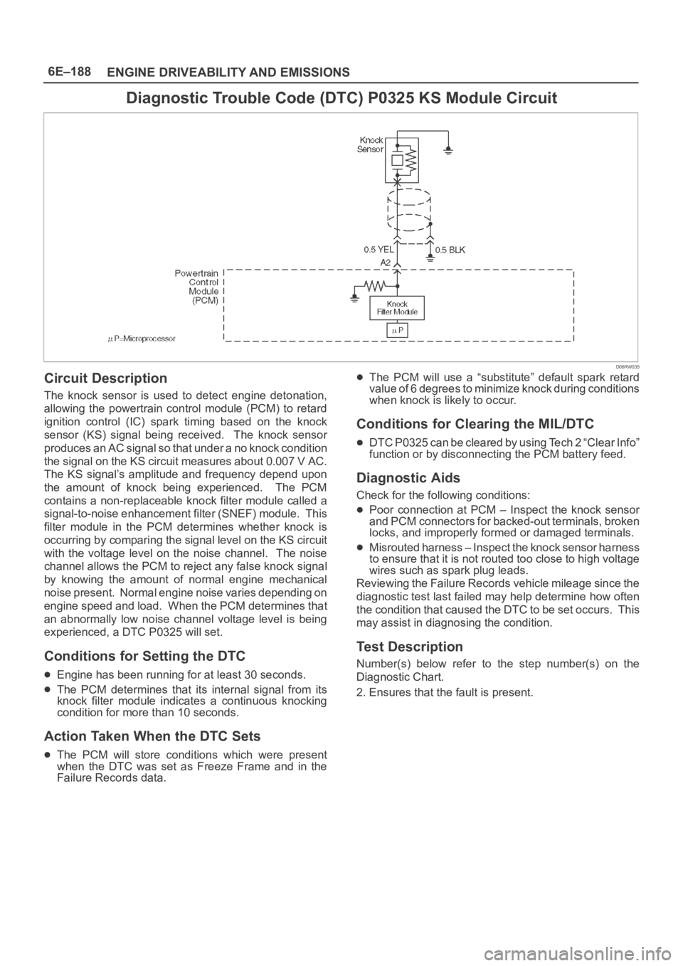
Diagnostic Trouble Code (DTC) P0325 KS Module Circuit
D06RW035
Circuit Description
The knock sensor is used to detect engine detonation,
allowing the powertrain control module (PCM) to retard
ignition control (IC) spark timing based on the knock
sensor (KS) signal being received. The knock sensor
produces an AC signal so that under a no knock condition
the signal on the KS circuit measures about 0.007 V AC.
The KS signal’s amplitude and frequency depend upon
the amount of knock being experienced. The PCM
contains a non-replaceable knock filter module called a
signal-to-noise enhancement filter (SNEF) module. This
filter module in the PCM determines whether knock is
occurring by comparing the signal level on the KS circuit
with the voltage level on the noise channel. The noise
channel allows the PCM to reject any false knock signal
by knowing the amount of normal engine mechanical
noise present. Normal engine noise varies depending on
engine speed and load. When the PCM determines that
an abnormally low noise channel voltage level is being
experienced, a DTC P0325 will set.
Conditions for Setting the DTC
Engine has been running for at least 30 seconds.
The PCM determines that its internal signal from its
knock filter module indicates a continuous knocking
condition for more than 10 seconds.
Action Taken When the DTC Sets
The PCM will store conditions which were present
when the DTC was set as Freeze Frame and in the
Failure Records data.
The PCM will use a “substitute” default spark retard
value of 6 degrees to minimize knock during conditions
when knock is likely to occur.
Conditions for Clearing the MIL/DTC
DTC P0325 can be cleared by using Tech 2 “Clear Info”
function or by disconnecting the PCM battery feed.
Diagnostic Aids
Check for the following conditions:
Poor connection at PCM – Inspect the knock sensor
and PCM connectors for backed-out terminals, broken
locks, and improperly formed or damaged terminals.
Misrouted harness – Inspect the knock sensor harness
to ensure that it is not routed too close to high voltage
wires such as spark plug leads.
Reviewing the Failure Records vehicle mileage since the
diagnostic test last failed may help determine how often
the condition that caused the DTC to be set occurs. This
may assist in diagnosing the condition.
Test Description
Number(s) below refer to the step number(s) on the
Diagnostic Chart.
2. Ensures that the fault is present.
Page 1307 of 6000
6E–190
ENGINE DRIVEABILITY AND EMISSIONS
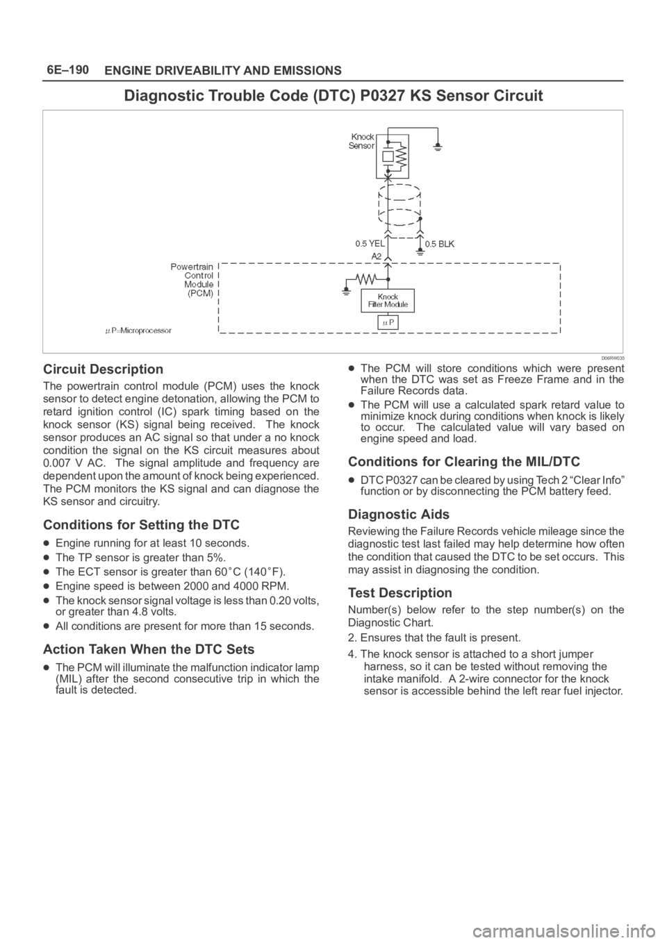
Diagnostic Trouble Code (DTC) P0327 KS Sensor Circuit
D06RW035
Circuit Description
The powertrain control module (PCM) uses the knock
sensor to detect engine detonation, allowing the PCM to
retard ignition control (IC) spark timing based on the
knock sensor (KS) signal being received. The knock
sensor produces an AC signal so that under a no knock
condition the signal on the KS circuit measures about
0.007 V AC. The signal amplitude and frequency are
dependent upon the amount of knock being experienced.
The PCM monitors the KS signal and can diagnose the
KS sensor and circuitry.
Conditions for Setting the DTC
Engine running for at least 10 seconds.
The TP sensor is greater than 5%.
The ECT sensor is greater than 60C (140F).
Engine speed is between 2000 and 4000 RPM.
The knock sensor signal voltage is less than 0.20 volts,
or greater than 4.8 volts.
All conditions are present for more than 15 seconds.
Action Taken When the DTC Sets
The PCM will illuminate the malfunction indicator lamp
(MIL) after the second consecutive trip in which the
fault is detected.
The PCM will store conditions which were present
when the DTC was set as Freeze Frame and in the
Failure Records data.
The PCM will use a calculated spark retard value to
minimize knock during conditions when knock is likely
to occur. The calculated value will vary based on
engine speed and load.
Conditions for Clearing the MIL/DTC
DTC P0327 can be cleared by using Tech 2 “Clear Info”
function or by disconnecting the PCM battery feed.
Diagnostic Aids
Reviewing the Failure Records vehicle mileage since the
diagnostic test last failed may help determine how often
the condition that caused the DTC to be set occurs. This
may assist in diagnosing the condition.
Test Description
Number(s) below refer to the step number(s) on the
Diagnostic Chart.
2. Ensures that the fault is present.
4. The knock sensor is attached to a short jumper
harness, so it can be tested without removing the
intake manifold. A 2-wire connector for the knock
sensor is accessible behind the left rear fuel injector.
Page 1381 of 6000
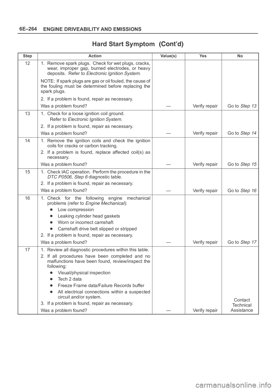
6E–264
ENGINE DRIVEABILITY AND EMISSIONS
Hard Start Symptom
StepNo Ye s Va l u e ( s ) Action
121. Remove spark plugs. Check for wet plugs, cracks,
wear, improper gap, burned electrodes, or heavy
deposits. Refer to
Electronic Ignition System.
NOTE: If spark plugs are gas or oil fouled, the cause of
the fouling must be determined before replacing the
spark plugs.
2. If a problem is found, repair as necessary.
Was a problem found?
—Verify repairGo to Step 13
131. Check for a loose ignition coil ground.
Refer to
Electronic Ignition System.
2. If a problem is found, repair as necessary.
Was a problem found?
—Verify repairGo to Step 14
141. Remove the ignition coils and check the ignition
coils for cracks or carbon tracking.
2. If a problem is found, replace affected coil(s) as
necessary.
Was a problem found?
—Verify repairGo to Step 15
151. Check IAC operation. Perform the procedure in the
DTC P0506, Step 6 diagnostic table.
2. If a problem is found, repair as necessary.
Was a problem found?
—Verify repairGo to Step 16
161. Check for the following engine mechanical
problems (refer to
Engine Mechanical):
Low compression
Leaking cylinder head gaskets
Worn or incorrect camshaft
Camshaft drive belt slipped or stripped
2. If a problem is found, repair as necessary.
Was a problem found?
—Verify repairGo to Step 17
171. Review all diagnostic procedures within this table.
2. If all procedures have been completed and no
malfunctions have been found, review/inspect the
following:
Visual/physical inspection
Te c h 2 d a t a
Freeze Frame data/Failure Records buffer
All electrical connections within a suspected
circuit and/or system.
3. If a problem is found, repair as necessary.
Was a problem found?
—Verify repair
Contact
Te c h n i c a l
Assistance
Page 1388 of 6000
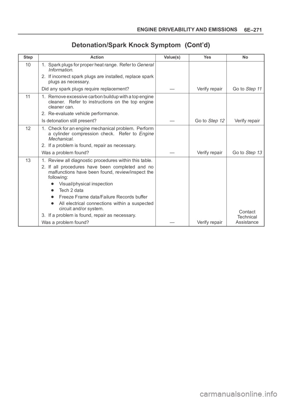
6E–271 ENGINE DRIVEABILITY AND EMISSIONS
Detonation/Spark Knock Symptom
StepNo Ye s Va l u e ( s ) Action
101. Spark plugs for proper heat range. Refer to General
Information
.
2. If incorrect spark plugs are installed, replace spark
plugs as necessary.
Did any spark plugs require replacement?
—Verify repairGo to Step 11
111. Remove excessive carbon buildup with a top engine
cleaner. Refer to instructions on the top engine
cleaner can.
2. Re-evaluate vehicle performance.
Is detonation still present?
—Go to Step 12Verify repair
121. Check for an engine mechanical problem. Perform
a cylinder compression check. Refer to
Engine
Mechanical
.
2. If a problem is found, repair as necessary.
Was a problem found?
—Verify repairGo to Step 13
131. Review all diagnostic procedures within this table.
2. If all procedures have been completed and no
malfunctions have been found, review/inspect the
following:
Visual/physical inspection
Te c h 2 d a t a
Freeze Frame data/Failure Records buffer
All electrical connections within a suspected
circuit and/or system.
3. If a problem is found, repair as necessary.
Was a problem found?
—Verify repair
Contact
Te c h n i c a l
Assistance
Page 3565 of 6000
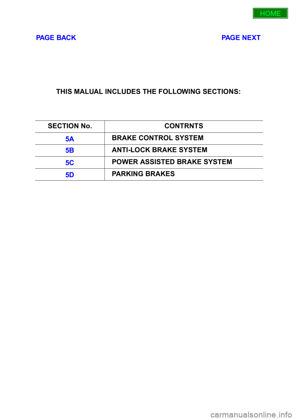
PAGE BACK PAGE NEXT
THIS MALUAL INCLUDES THE FOLLOWING SECTIONS:
SECTION No. CONTRNTS
5A BRAKE CONTROL SYSTEM
5B ANTI-LOCK BRAKE SYSTEM
5C POWER ASSISTED BRAKE SYSTEM
5D PARKING BRAKES
HOME
5A
5B
5C
5D
Page 4351 of 6000
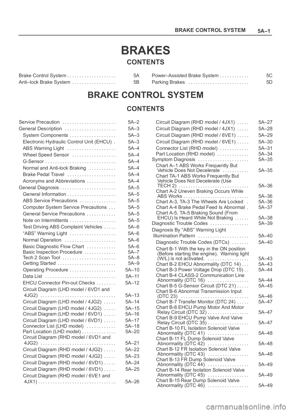
5A–1 BRAKE CONTROL SYSTEM
BRAKES
CONTENTS
Brake Control System 5A. . . . . . . . . . . . . . . . . . . .
Anti–lock Brake System 5B. . . . . . . . . . . . . . . . . . Power–Assisted Brake System 5C. . . . . . . . . . . .
Parking Brakes 5D. . . . . . . . . . . . . . . . . . . . . . . . .
BRAKE CONTROL SYSTEM
CONTENTS
Service Precaution 5A–2. . . . . . . . . . . . . . . . . . . . . .
General Description 5A–3. . . . . . . . . . . . . . . . . . . . .
System Components 5A–3. . . . . . . . . . . . . . . . . . .
Electronic Hydraulic Control Unit (EHCU) 5A–3.
ABS Warning Light 5A–4. . . . . . . . . . . . . . . . . . . .
Wheel Speed Sensor 5A–4. . . . . . . . . . . . . . . . . .
G-Sensor 5A–4. . . . . . . . . . . . . . . . . . . . . . . . . . . . .
Normal and Anti-lock Braking 5A–4. . . . . . . . . . .
Brake Pedal Travel 5A–4. . . . . . . . . . . . . . . . . . . .
Acronyms and Abbreviations 5A–4. . . . . . . . . . . .
General Diagnosis 5A–5. . . . . . . . . . . . . . . . . . . . . . .
General Information 5A–5. . . . . . . . . . . . . . . . . . . .
ABS Service Precautions 5A–5. . . . . . . . . . . . . . .
Computer System Service Precautions 5A–5. . .
General Service Precautions 5A–5. . . . . . . . . . . .
Note on Intermittents 5A–5. . . . . . . . . . . . . . . . . . .
Test Driving ABS Complaint Vehicles 5A–6. . . . .
“ABS” Warning Light 5A–6. . . . . . . . . . . . . . . . . . .
Normal Operation 5A–6. . . . . . . . . . . . . . . . . . . . .
Basic Diagnostic Flow Chart 5A–6. . . . . . . . . . . .
Basic Inspection Procedure 5A–7. . . . . . . . . . . . .
Tech 2 Scan Tool 5A–8. . . . . . . . . . . . . . . . . . . . . .
Getting Started 5A–9. . . . . . . . . . . . . . . . . . . . . . . .
Operating Procedure 5A–10. . . . . . . . . . . . . . . . . . .
Data List 5A–11. . . . . . . . . . . . . . . . . . . . . . . . . . . . .
EHCU Connector Pin-out Checks 5A–12. . . . . . . .
Circuit Diagram (LHD model / 6VD1 and
4JG2) 5A–13. . . . . . . . . . . . . . . . . . . . . . . . . . . . . . .
Circuit Diagram (LHD model / 4JG2) 5A–14. . . . .
Circuit Diagram (LHD model / 4JG2) 5A–15. . . . .
Circuit Diagram (LHD model / 6VD1) 5A–16. . . . .
Circuit Diagram (LHD model / 6VD1) 5A–17. . . . .
Connector List (LHD model) 5A–18. . . . . . . . . . . .
Part Location (LHD model) 5A–20. . . . . . . . . . . . . .
Circuit Diagram (RHD model / 6VD1 and
4JG2) 5A–21. . . . . . . . . . . . . . . . . . . . . . . . . . . . . . .
Circuit Diagram (RHD model / 4JG2) 5A–22. . . . .
Circuit Diagram (RHD model / 4JG2) 5A–23. . . . .
Circuit Diagram (RHD model / 6VD1) 5A–24. . . . .
Circuit Diagram (RHD model / 6VD1) 5A–25. . . . .
Circuit Diagram (RHD model / 6VE1 and
4JX1) 5A–26. . . . . . . . . . . . . . . . . . . . . . . . . . . . . . . . Circuit Diagram (RHD model / 4JX1) 5A–27. . . . .
Circuit Diagram (RHD model / 4JX1) 5A–28. . . . .
Circuit Diagram (RHD model / 6VE1) 5A–29. . . . .
Circuit Diagram (RHD model / 6VE1) 5A–30. . . . .
Connector List (RHD model) 5A–31. . . . . . . . . . . .
Part Location (RHD model) 5A–34. . . . . . . . . . . . .
Symptom Diagnosis 5A–35. . . . . . . . . . . . . . . . . . . . .
Chart A–1 ABS Works Frequently But
Vehicle Does Not Decelerate 5A–35. . . . . . . . . . .
Chart TA-1 ABS Works Frequently But
Vehicle Does Not Decelerate (Use
TECH 2) 5A–36. . . . . . . . . . . . . . . . . . . . . . . . . . . . .
Chart A-2 Uneven Braking Occurs While
ABS Works 5A–36. . . . . . . . . . . . . . . . . . . . . . . . . . .
Chart A-3, TA-3 The Wheels Are Locked 5A–36.
Chart A-4 Brake Pedal Feed Is Abnormal 5A–37.
Chart A-5, TA-5 Braking Sound (From
EHCU) Is Heard While Not Braking 5A–38. . . . . .
Diagnostic Trouble Codes 5A–39. . . . . . . . . . . . . . . .
Diagnosis By “ABS” Warning Light
Illumination Pattern 5A–40. . . . . . . . . . . . . . . . . . . . .
Diagnostic Trouble Codes (DTCs) 5A–40. . . . . . .
Chart B-1 With the key in the ON position
(Before starting the engine). Warning light
(W/L) is not activated. 5A–43. . . . . . . . . . . . . . . . .
Chart B-2 EHCU Abnormality (DTC 14) 5A–43. . .
Chart B-3 Power Voltage Drop (DTC 15) 5A–44. .
Chart B-4 CLASS-2 Communication Line
Abnormality (DTC 16) 5A–44. . . . . . . . . . . . . . . . .
Chart B-5 G-Sensor Circuit (DTC 21) 5A–45. . . . .
Chart B-6 Abnormal Transmission Input
(DTC 23) 5A–46. . . . . . . . . . . . . . . . . . . . . . . . . . . .
Chart B-7 Transfer Monitor (DTC 24) 5A–47. . . . .
Chart B-8 EHCU Pump Motor And Motor
Relay Circuit (DTC 32) 5A–47. . . . . . . . . . . . . . . . .
Chart B-9 EHCU Pump Valve And Valve
Relay Circuit (DTC 35) 5A–47. . . . . . . . . . . . . . . . .
Chart B-10 FL Isolation Solenoid Valve
Abnormality (DTC 41) 5A–48. . . . . . . . . . . . . . . . .
Chart B-11 FL Dump Solenoid Valve
Abnormality (DTC 42) 5A–48. . . . . . . . . . . . . . . . .
Chart B-12 FR Isolation Solenoid Valve
Abnormality (DTC 43) 5A–48. . . . . . . . . . . . . . . . .
Chart B-13 FR Dump Solenoid Valve
Abnormality (DTC 44) 5A–49. . . . . . . . . . . . . . . . .
Chart B-14 Rear Isolation Solenoid Valve
Abnormality (DTC 45) 5A–49. . . . . . . . . . . . . . . . .
Chart B-15 Rear Dump Solenoid Valve
Abnormality (DTC 46) 5A–49. . . . . . . . . . . . . . . . .