1998 OPEL FRONTERA jump start
[x] Cancel search: jump startPage 815 of 6000

5A–5 BRAKE CONTROL SYSTEM
FR
Front Right
GEN
Generator
MV
Millivolts
RL
Rear Left
RR
Rear RightRPS
Revolution per Second
VDC
Vo l t s D C
VA C
Vo l t s A C
W/L
Warning Light
WSS
Wheel Speed Sensor
General Diagnosis
General Information
ABS malfunction can be classified into two types, those
which can be detected by the ABS warning light and those
which can be detected as a vehicle abnormality by the
driver.
In either case, locate the fault in accordance with the
“BASIC DIAGNOSTIC FLOWCHART” and repair.
Please refer to Section 5C for the diagnosis of
mechanical troubles such as brake noise, brake judder
(brake pedal or vehicle vibration felt when braking),
uneven braking, and parking brake trouble.
ABS Service Precautions
Required Tools and Items:
Box Wrench
Brake Fluid
Special Tool
Some diagnosis procedures in this section require the
installation of a special tool.
J-39200 High Impedance Multimeter
When circuit measurements are requested, use a circuit
tester with high impedance.
Computer System Service Precautions
The Anti-lock Brake System interfaces directly with the
Electronic Hydraulic Control Unit (EHCU) which is a
control computer that is similar in some regards to the
Powertrain Control Module. These modules are designed
to withstand normal current draws associated with
vehicle operation. However, care must be taken to avoid
overloading any of the EHCU circuits. In testing for opens
or shorts, do not ground or apply voltage to any of the
circuits unless instructed to do so by the appropriate
diagnostic procedure. These circuits should only be
tested with a high impedance multimeter (J-39200) or
special tools as described in this section. Power should
never be removed or applied to any control module with
the ignition in the “ON” position.
Before removing or connecting battery cables, fuses or
connectors, always turn the ignition switch to the “OFF”
position.
General Service Precautions
The following are general precautions which should be
observed when servicing and diagnosing the Anti-lock
Brake System and/or other vehicle systems. Failure toobserve these precautions may result in Anti-lock Brake
System damage.
If welding work is to be performed on the vehicle using
an electric arc welder, the EHCU and valve block
connectors should be disconnected before the
welding operation begins.
The EHCU and valve block connectors should never
be connected or disconnected with the ignition “ON” .
EHCU of the Anti-lock Brake System are not
separately serviceable and must be replaced as
assemblies. Do not disassemble any component
which is designated as non-serviceable in this
Section.
If only rear wheels are rotated using jacks or drum
tester, the system will diagnose a speed sensor
malfunction and the “ABS” warning light will
illuminate. But actually no trouble exists. After
inspection stop the engine once and re-start it, then
make sure that the “ABS” warning light does not
illuminate.
If the battery has been discharged
The engine may stall if the battery has been completely
discharged and the engine is started via jumper cables.
This is because the Anti-lock Brake System (ABS)
requires a large quantity of electricity. In this case, wait
until the battery is recharged, or set the ABS to a
non-operative state by removing the fuse for the ABS
(40A). After the battery has been recharged, stop the
engine and install the ABS fuse. Start the engine again,
and confirm that the ABS warning light does not light.
Note on Intermittents
As with virtually any electronic system, it is difficult to
identify an intermittent failure. In such a case duplicating
the system malfunction during a test drive or a good
description of vehicle behavior from the customer may be
helpful in locating a “most likely” failed component or
circuit. The symptom diagnosis chart may also be useful
in isolating the failure. Most intermittent problems are
caused by faulty electrical connections or wiring. When
an intermittent failure is encountered, check suspect
circuits for:
Suspected harness damage.
Poor mating of connector halves or terminals not fully
seated in the connector body (backed out).
Improperly formed or damaged terminals.
Page 960 of 6000
6A–4
ENGINE MECHANICAL
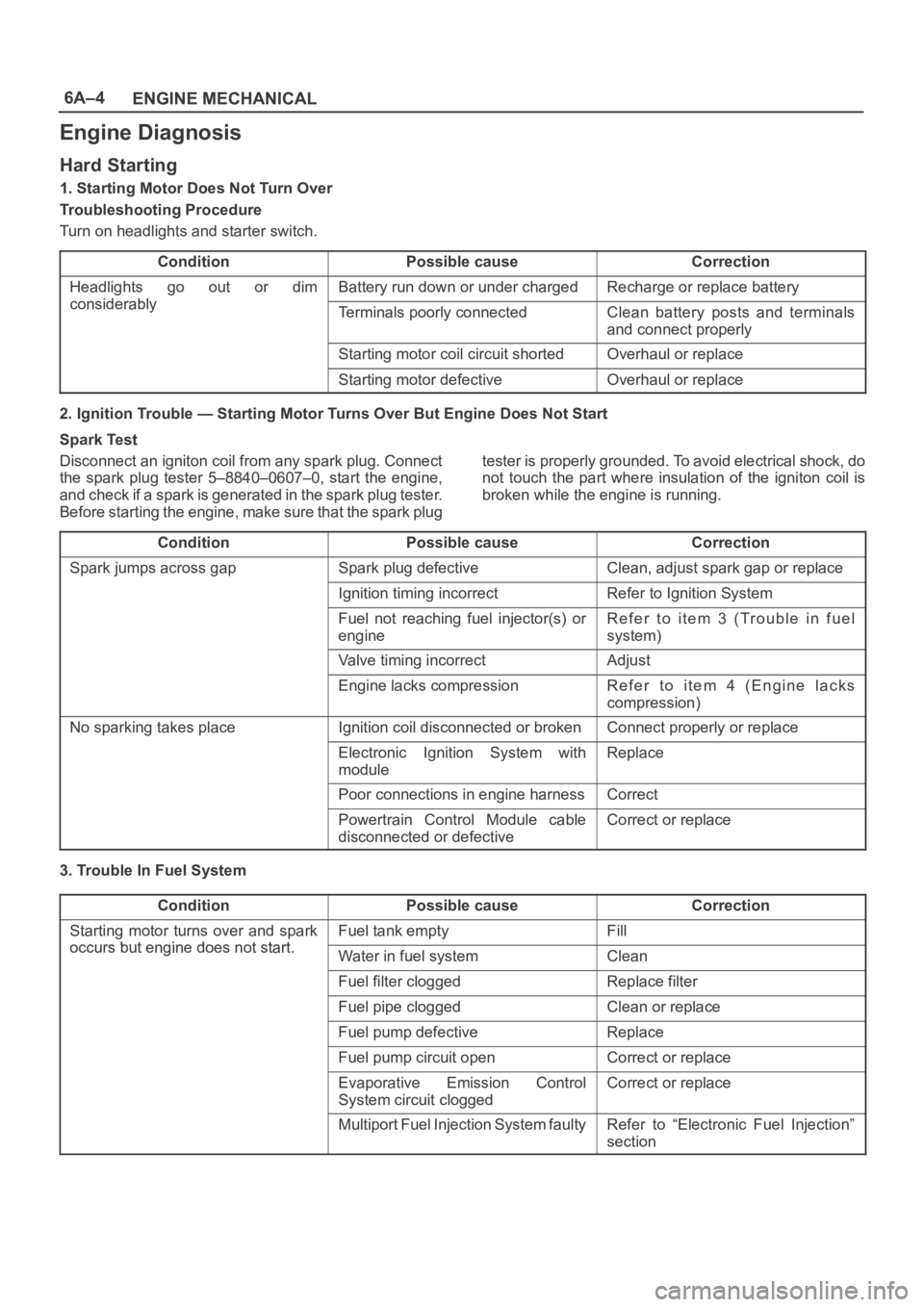
Engine Diagnosis
Hard Starting
1. Starting Motor Does Not Turn Over
Troubleshooting Procedure
Turn on headlights and starter switch.
Condition
Possible causeCorrection
Headlights go out or dim
considerably
Battery run down or under chargedRecharge or replace battery
considerablyTerminals poorly connectedClean battery posts and terminals
and connect properly
Starting motor coil circuit shortedOverhaul or replace
Starting motor defectiveOverhaul or replace
2. Ignition Trouble — Starting Motor Turns Over But Engine Does Not Start
Spark Test
Disconnect an igniton coil from any spark plug. Connect
the spark plug tester 5–8840–0607–0, start the engine,
a n d c h e c k i f a s p a r k i s g e n e r a t e d in t h e s p a r k p l u g t e s t e r.
Before starting the engine, make sure that the spark plugtester is properly grounded. To avoid electrical shock, do
not touch the part where insulation of the igniton coil is
broken while the engine is running.
Condition
Possible causeCorrection
Spark jumps across gapSpark plug defectiveClean, adjust spark gap or replace
Ignition timing incorrectRefer to Ignition System
Fuel not reaching fuel injector(s) or
engineRefer to item 3 (Trouble in fuel
system)
Valve timing incorrectAdjust
Engine lacks compressionRefer to item 4 (Engine lacks
compression)
No sparking takes placeIgnition coil disconnected or brokenConnect properly or replace
Electronic Ignition System with
moduleReplace
Poor connections in engine harnessCorrect
Powertrain Control Module cable
disconnected or defectiveCorrect or replace
3. Trouble In Fuel System
Condition
Possible causeCorrection
Starting motor turns over and spark
occurs but engine does not start
Fuel tank emptyFill
occurs but engine does not start.Water in fuel systemClean
Fuel filter cloggedReplace filter
Fuel pipe cloggedClean or replace
Fuel pump defectiveReplace
Fuel pump circuit openCorrect or replace
Evaporative Emission Control
System circuit cloggedCorrect or replace
Multiport Fuel Injection System faultyRefer to “Electronic Fuel Injection”
section
Page 1072 of 6000
6C–5
ENGINE FUEL
Installation
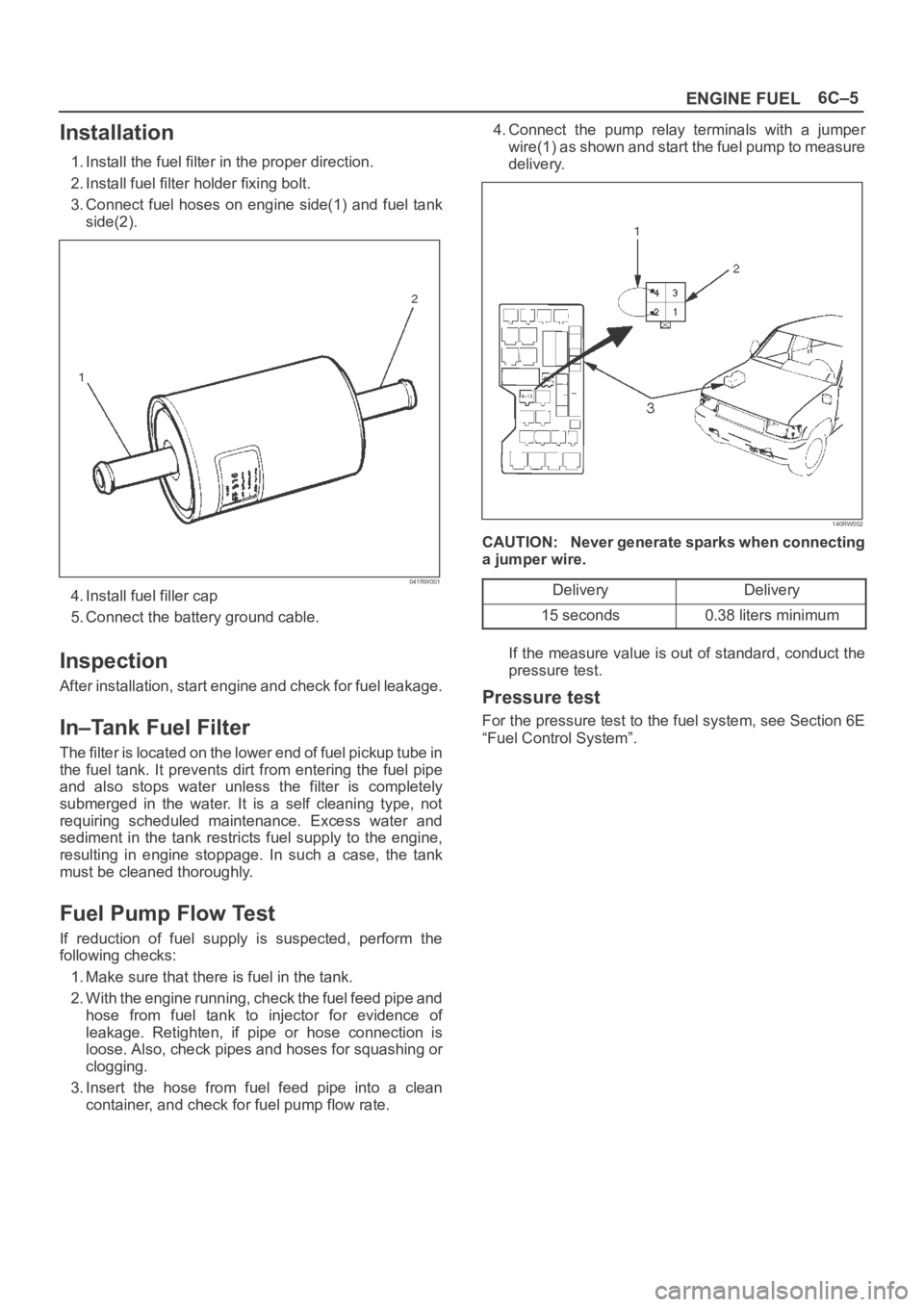
1. Install the fuel filter in the proper direction.
2. Install fuel filter holder fixing bolt.
3. Connect fuel hoses on engine side(1) and fuel tank
side(2).
041RW001
4. Install fuel filler cap
5. Connect the battery ground cable.
Inspection
After installation, start engine and check for fuel leakage.
In–Tank Fuel Filter
The filter is located on the lower end of fuel pickup tube in
the fuel tank. It prevents dirt from entering the fuel pipe
and also stops water unless the filter is completely
submerged in the water. It is a self cleaning type, not
requiring scheduled maintenance. Excess water and
sediment in the tank restricts fuel supply to the engine,
resulting in engine stoppage. In such a case, the tank
must be cleaned thoroughly.
Fuel Pump Flow Test
If reduction of fuel supply is suspected, perform the
following checks:
1. Make sure that there is fuel in the tank.
2. With the engine running, check the fuel feed pipe and
hose from fuel tank to injector for evidence of
leakage. Retighten, if pipe or hose connection is
loose. Also, check pipes and hoses for squashing or
clogging.
3. Insert the hose from fuel feed pipe into a clean
container, and check for fuel pump flow rate.4. Connect the pump relay terminals with a jumper
wire(1) as shown and start the fuel pump to measure
delivery.
140RW002
CAUTION: Never generate sparks when connecting
a jumper wire.
Delivery
Delivery
15 seconds0.38 liters minimum
If the measure value is out of standard, conduct the
pressure test.
Pressure test
For the pressure test to the fuel system, see Section 6E
“Fuel Control System”.
Page 1080 of 6000
ENGINE ELECTRICAL6D1–1
ENGINE
ENGINE ELECTRICAL
CONTENTS
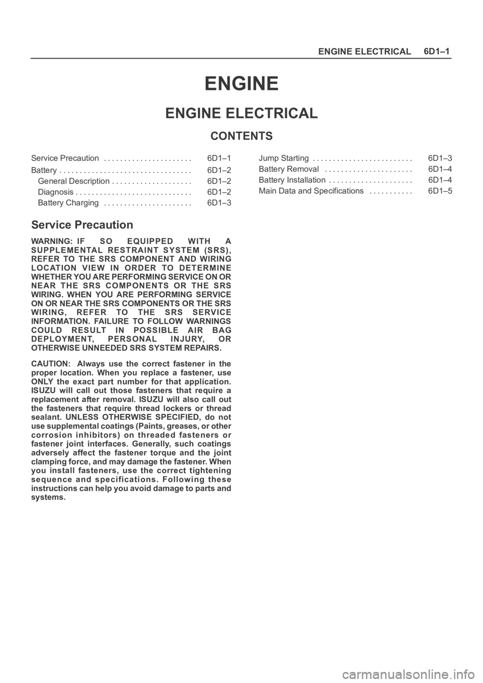
Service Precaution 6D1–1. . . . . . . . . . . . . . . . . . . . . .
Battery 6D1–2. . . . . . . . . . . . . . . . . . . . . . . . . . . . . . . . .
General Description 6D1–2. . . . . . . . . . . . . . . . . . . .
Diagnosis 6D1–2. . . . . . . . . . . . . . . . . . . . . . . . . . . . .
Battery Charging 6D1–3. . . . . . . . . . . . . . . . . . . . . . Jump Starting 6D1–3. . . . . . . . . . . . . . . . . . . . . . . . .
Battery Removal 6D1–4. . . . . . . . . . . . . . . . . . . . . .
Battery Installation 6D1–4. . . . . . . . . . . . . . . . . . . . .
Main Data and Specifications 6D1–5. . . . . . . . . . .
Service Precaution
WARNING: IF SO EQUIPPED WITH A
SUPPLEMENTAL RESTRAINT SYSTEM (SRS),
REFER TO THE SRS COMPONENT AND WIRING
LOCATION VIEW IN ORDER TO DETERMINE
WHETHER YOU ARE PERFORMING SERVICE ON OR
NEAR THE SRS COMPONENTS OR THE SRS
WIRING. WHEN YOU ARE PERFORMING SERVICE
ON OR NEAR THE SRS COMPONENTS OR THE SRS
WIRING, REFER TO THE SRS SERVICE
INFORMATION. FAILURE TO FOLLOW WARNINGS
COULD RESULT IN POSSIBLE AIR BAG
DEPLOYMENT, PERSONAL INJURY, OR
OTHERWISE UNNEEDED SRS SYSTEM REPAIRS.
CAUTION: Always use the correct fastener in the
proper location. When you replace a fastener, use
ONLY the exact part number for that application.
ISUZU will call out those fasteners that require a
replacement after removal. ISUZU will also call out
the fasteners that require thread lockers or thread
sealant. UNLESS OTHERWISE SPECIFIED, do not
use supplemental coatings (Paints, greases, or other
corrosion inhibitors) on threaded fasteners or
fastener joint interfaces. Generally, such coatings
adversely affect the fastener torque and the joint
clamping force, and may damage the fastener. When
you install fasteners, use the correct tightening
sequence and specifications. Following these
instructions can help you avoid damage to parts and
systems.
Page 1082 of 6000
ENGINE ELECTRICAL6D1–3
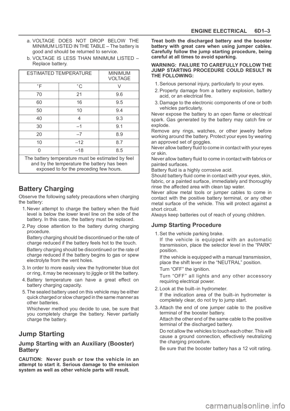
a. VOLTAGE DOES NOT DROP BELOW THE
MINIMUM LISTED IN THE TABLE – The battery is
good and should be returned to service.
b. VOLTAGE IS LESS THAN MINIMUM LISTED –
Replace battery.
ESTIMATED TEMPERATURE
MINIMUM
VOLTAGE
FCV
70219.6
60169.5
50109.4
4049.3
30–19.1
20–78.9
10–128.7
0–188.5
The battery temperature must be estimated by feel
and by the temperature the battery has been
exposed to for the preceding few hours.
Battery Charging
Observe the following safety precautions when charging
the battery:
1. Never attempt to charge the battery when the fluid
level is below the lower level line on the side of the
battery. In this case, the battery must be replaced.
2. Pay close attention to the battery during charging
procedure.
Battery charging should be discontinued or the rate of
charge reduced if the battery feels hot to the touch.
Battery charging should be discontinued or the rate of
charge reduced if the battery begins to gas or spew
electrolyte from the vent holes.
3. In order to more easily view the hydrometer blue dot
or ring, it may be necessary to jiggle or tilt the battery.
4. Battery temperature can have a great effect on
battery charging capacity.
5. The sealed battery used on this vehicle may be either
quick charged or slow charged in the same manner as
other batteries.
Whichever method you decide to use, be sure that
you completely charge the battery. Never partially
charge the battery.
Jump Starting
Jump Starting with an Auxiliary (Booster)
Battery
CAUTION: Never push or tow the vehicle in an
attempt to start it. Serious damage to the emission
system as well as other vehicle parts will result.Treat both the discharged battery and the booster
battery with great care when using jumper cables.
Carefully follow the jump starting procedure, being
careful at all times to avoid sparking.
WARNING: FAILURE TO CAREFULLY FOLLOW THE
JUMP STARTING PROCEDURE COULD RESULT IN
THE FOLLOWING:
1. Serious personal injury, particularly to your eyes.
2. Property damage from a battery explosion, battery
acid, or an electrical fire.
3. Damage to the electronic components of one or both
vehicles particularly.
Never expose the battery to an open flame or electrical
spark. Gas generated by the battery may catch fire or
explode.
Remove any rings, watches, or other jewelry before
working around the battery. Protect your eyes by wearing
an approved set of goggles.
Never allow battery fluid to come in contact with your eyes
or skin.
Never allow battery fluid to come in contact with fabrics or
painted surfaces.
Battery fluid is a highly corrosive acid.
Should battery fluid come in contact with your eyes, skin,
fabric, or a painted surface, immediately and thoroughly
rinse the affected area with clean tap water.
Never allow metal tools or jumper cables to come in
contact with the positive battery terminal, or any other
metal surface of the vehicle. This will protect against a
short circuit.
Always keep batteries out of reach of young children.
Jump Starting Procedure
1. Set the vehicle parking brake.
If the vehicle is equipped with an automatic
transmission, place the selector level in the “PARK”
position.
If the vehicle is equipped with a manual transmission,
place the shift lever in the “NEUTRAL” position.
Turn “OFF” the ignition.
Turn “OFF” all lights and any other accessory
requiring electrical power.
2. Look at the built–in hydrometer.
If the indication area of the built–in hydrometer is
completely clear, do not try to jump start.
3. Attach the end of one jumper cable to the positive
terminal of the booster battery.
Attach the other end of the same cable to the positive
terminal of the discharged battery.
Do not allow the vehicles to touch each other. This will
cause a ground connection, effectively neutralizing
the charging procedure.
Be sure that the booster battery has a 12 volt rating.
Page 1083 of 6000
6D1–4
ENGINE ELECTRICAL
4. Attach one end of the remaining cable to the negative
terminal of the booster battery.
Attach the other end of the same cable to a solid
engine ground (such as the air conditioning
compressor bracket or the generator mounting
bracket) of the vehicle with the discharged battery.
The ground connection must be at least 450 mm (18
in.) from the battery of the vehicle whose battery is
being charged.
WARNING: NEVER ATTACH THE END OF THE
JUMPER CABLE DIRECTLY TO THE NEGATIVE
TERMINAL OF THE DEAD BATTERY.
5. Start the engine of the vehicle with the good battery.
Make sure that all unnecessary electrical accessories
have been turned “OFF”.
6. Start the engine of the vehicle with the dead battery.
7. To remove the jumper cables, follow the above
directions in reverse order.
Be sure to first disconnect the negative cable from the
vehicle with the discharged battery.
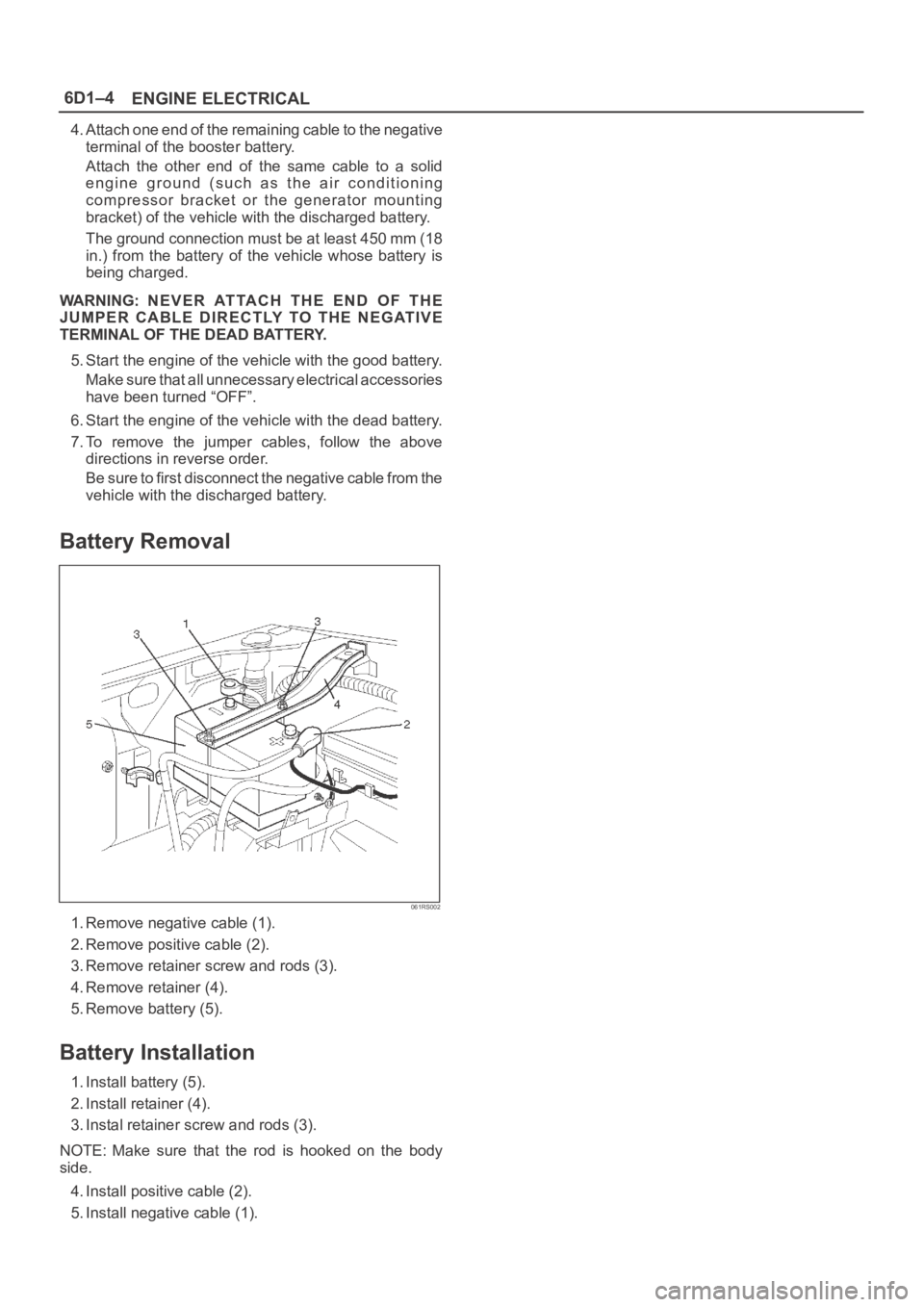
Battery Removal
061RS002
1. Remove negative cable (1).
2. Remove positive cable (2).
3. Remove retainer screw and rods (3).
4. Remove retainer (4).
5. Remove battery (5).
Battery Installation
1. Install battery (5).
2. Install retainer (4).
3. Instal retainer screw and rods (3).
NOTE: Make sure that the rod is hooked on the body
side.
4. Install positive cable (2).
5. Install negative cable (1).
Page 1104 of 6000
6D3–13 STARTING AND CHARGING SYSTEM
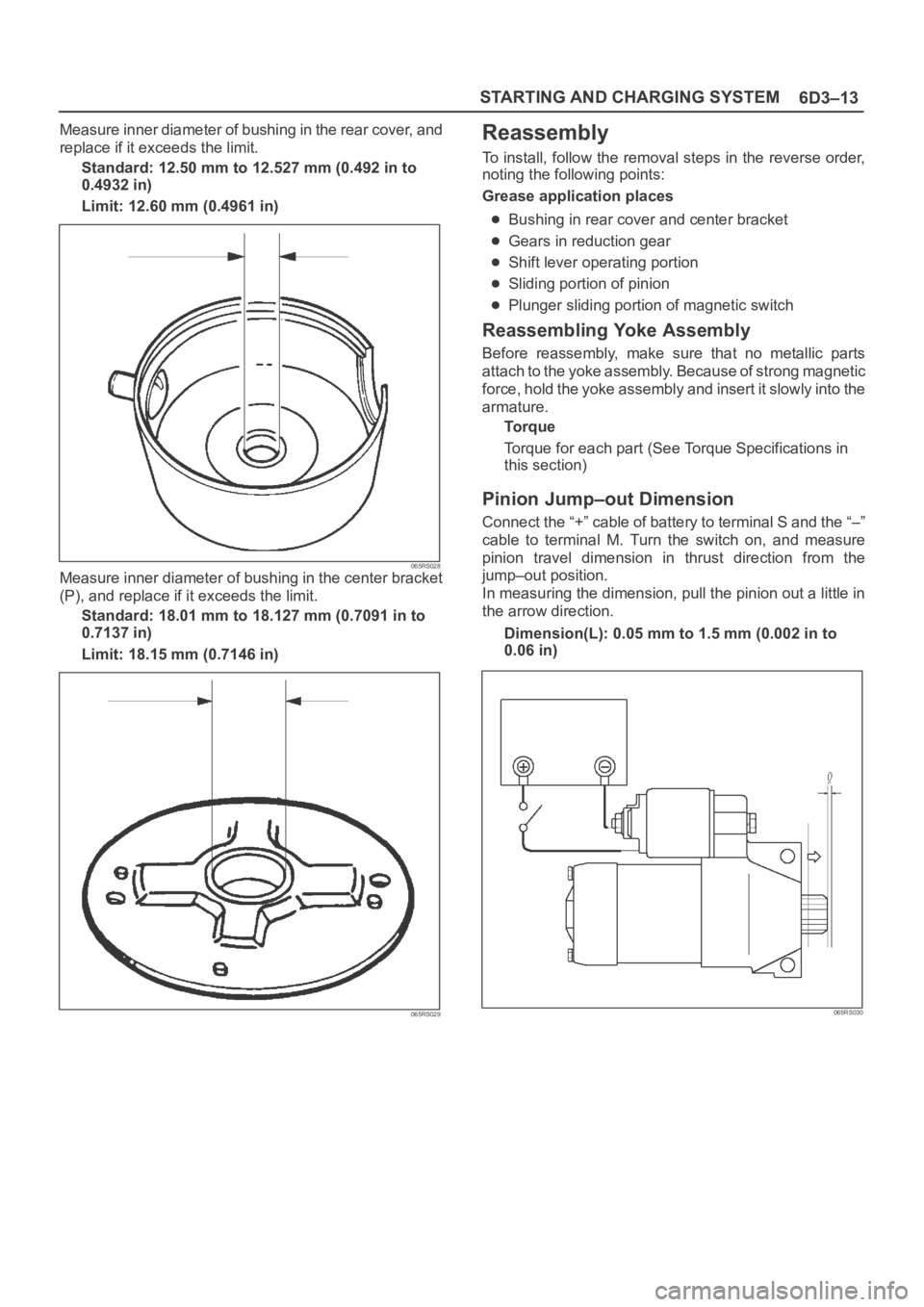
Measure inner diameter of bushing in the rear cover, and
replace if it exceeds the limit.
Standard: 12.50 mm to 12.527 mm (0.492 in to
0.4932 in)
Limit: 12.60 mm (0.4961 in)
065RS028Measure inner diameter of bushing in the center bracket
(P), and replace if it exceeds the limit.
Standard: 18.01 mm to 18.127 mm (0.7091 in to
0.7137 in)
Limit: 18.15 mm (0.7146 in)
065RS029
Reassembly
To install, follow the removal steps in the reverse order,
noting the following points:
Grease application places
Bushing in rear cover and center bracket
Gears in reduction gear
Shift lever operating portion
Sliding portion of pinion
Plunger sliding portion of magnetic switch
Reassembling Yoke Assembly
Before reassembly, make sure that no metallic parts
attach to the yoke assembly. Because of strong magnetic
force, hold the yoke assembly and insert it slowly into the
armature.
To r q u e
Torque for each part (See Torque Specifications in
this section)
Pinion Jump–out Dimension
Connect the “+” cable of battery to terminal S and the “–”
cable to terminal M. Turn the switch on, and measure
pinion travel dimension in thrust direction from the
jump–out position.
In measuring the dimension, pull the pinion out a little in
the arrow direction.
Dimension(L): 0.05 mm to 1.5 mm (0.002 in to
0.06 in)
065RS030
Page 1192 of 6000
6E–75 ENGINE DRIVEABILITY AND EMISSIONS
17.This vehicle is equipped with a PCM which utilizes
an electrically erasable programmable read only
memory (EEPROM). When the PCM is replaced,
the new PCM must be programmed. Refer to
UBS
98 model year Immobilizer Workshop Manual.
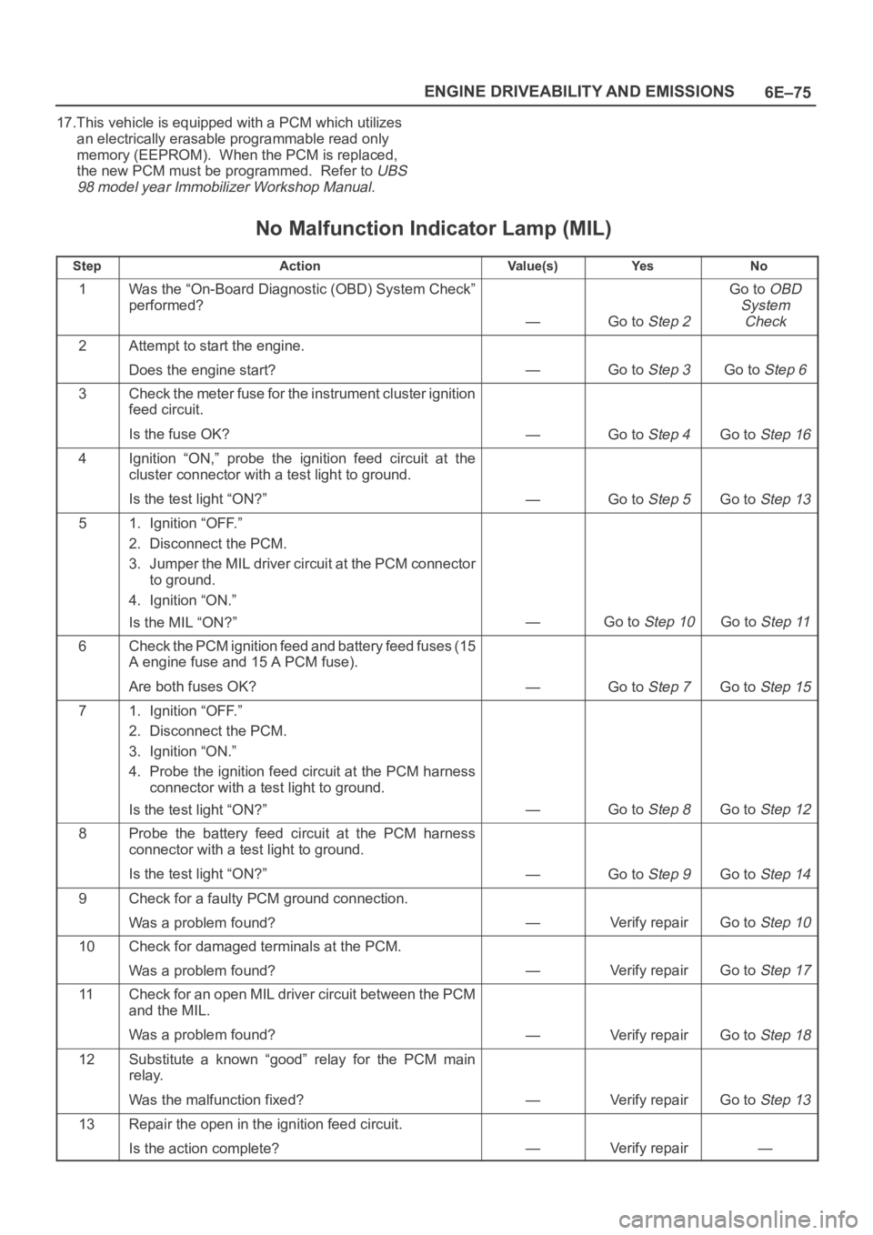
No Malfunction Indicator Lamp (MIL)
StepActionVa l u e ( s )Ye sNo
1Was the “On-Board Diagnostic (OBD) System Check”
performed?
—Go to Step 2
Go to OBD
System
Check
2Attempt to start the engine.
Does the engine start?
—Go to Step 3Go to Step 6
3Check the meter fuse for the instrument cluster ignition
feed circuit.
Is the fuse OK?
—Go to Step 4Go to Step 16
4Ignition “ON,” probe the ignition feed circuit at the
cluster connector with a test light to ground.
Is the test light “ON?”
—Go to Step 5Go to Step 13
51. Ignition “OFF.”
2. Disconnect the PCM.
3. Jumper the MIL driver circuit at the PCM connector
to ground.
4. Ignition “ON.”
Is the MIL “ON?”
—Go to Step 10Go to Step 11
6Check the PCM ignition feed and battery feed fuses (15
A engine fuse and 15 A PCM fuse).
Are both fuses OK?
—Go to Step 7Go to Step 15
71. Ignition “OFF.”
2. Disconnect the PCM.
3. Ignition “ON.”
4. Probe the ignition feed circuit at the PCM harness
connector with a test light to ground.
Is the test light “ON?”
—Go to Step 8Go to Step 12
8Probe the battery feed circuit at the PCM harness
connector with a test light to ground.
Is the test light “ON?”
—Go to Step 9Go to Step 14
9Check for a faulty PCM ground connection.
Was a problem found?
—Verify repairGo to Step 10
10Check for damaged terminals at the PCM.
Was a problem found?
—Verify repairGo to Step 17
11Check for an open MIL driver circuit between the PCM
and the MIL.
Was a problem found?
—Verify repairGo to Step 18
12Substitute a known “good” relay for the PCM main
relay.
Was the malfunction fixed?
—Verify repairGo to Step 13
13Repair the open in the ignition feed circuit.
Is the action complete?
—Verify repair—