1998 OPEL FRONTERA remote control
[x] Cancel search: remote controlPage 764 of 6000
TRANSFER CASE (STANDARD TYPE)
4D1–43
Main Data and Specifications
General Specifications
Ty p eW/Shift On The Fly System model
Synchronized type gears shifting between the 2 and 4 wheel drive mode.
Constant mesh type gears shifting between “low” and “high”.
WO/Shift On The Fly System model
Constant mesh type gears shifting between the 2 and 4 wheel drive mode,
and between “low” and “high”.
Control methodW/4WD Switch model
Electric control with the button switch on the instrument panel for gear
shifting between the 2 and 4 wheel drive mode.
Remote control with the gear shift lever on the floor for gear shifting
between “low and high” .
WO/4WD Switch model
Remote control with the gear shift lever on the floor for gear shifting.
Gear ratioHigh; 1.000
Low; 2.050
Oil capacity1.45 lit. (1.53 U.S. quart)
Type of lubricantEngine oil
Refer to chart in Section 0
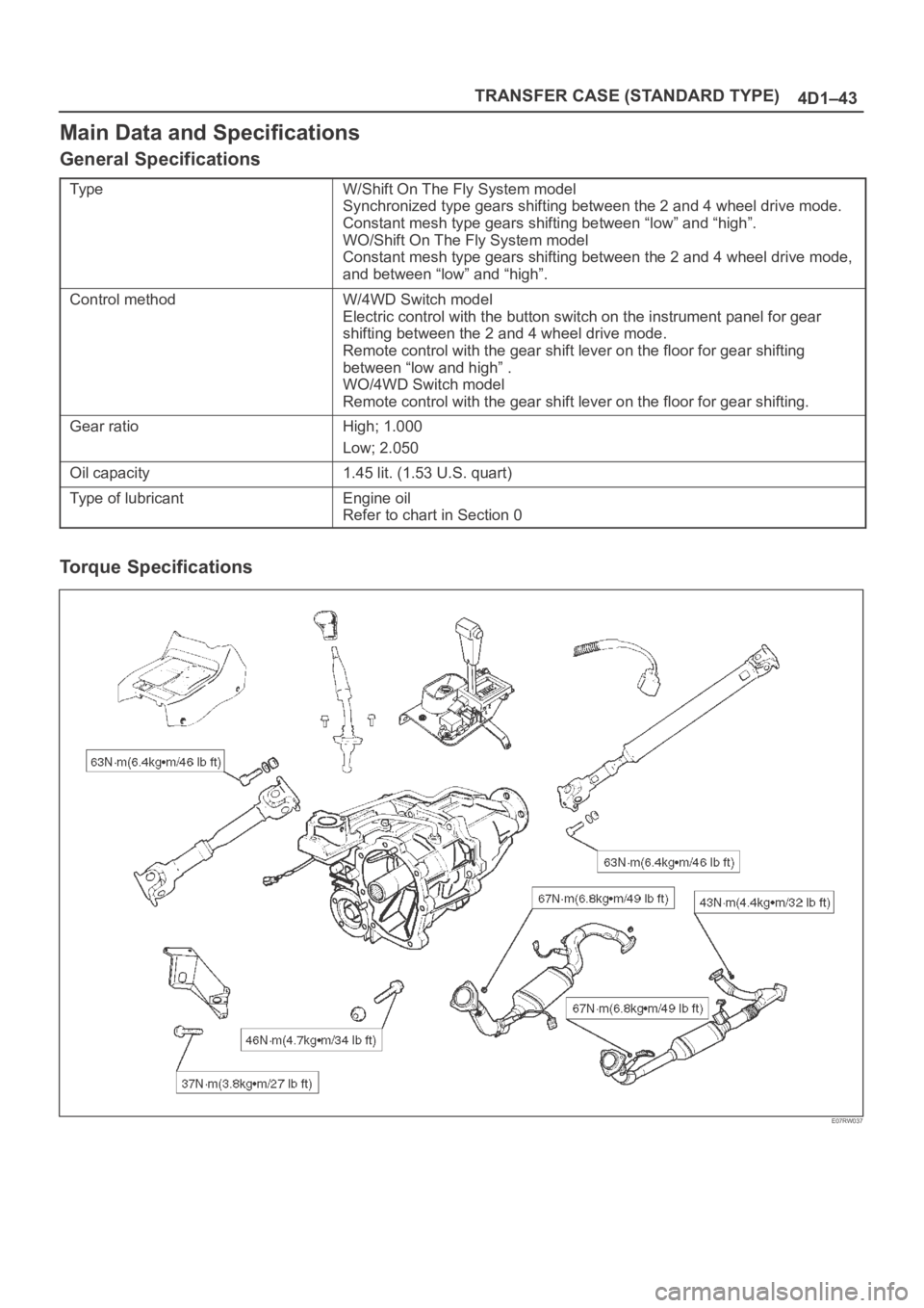
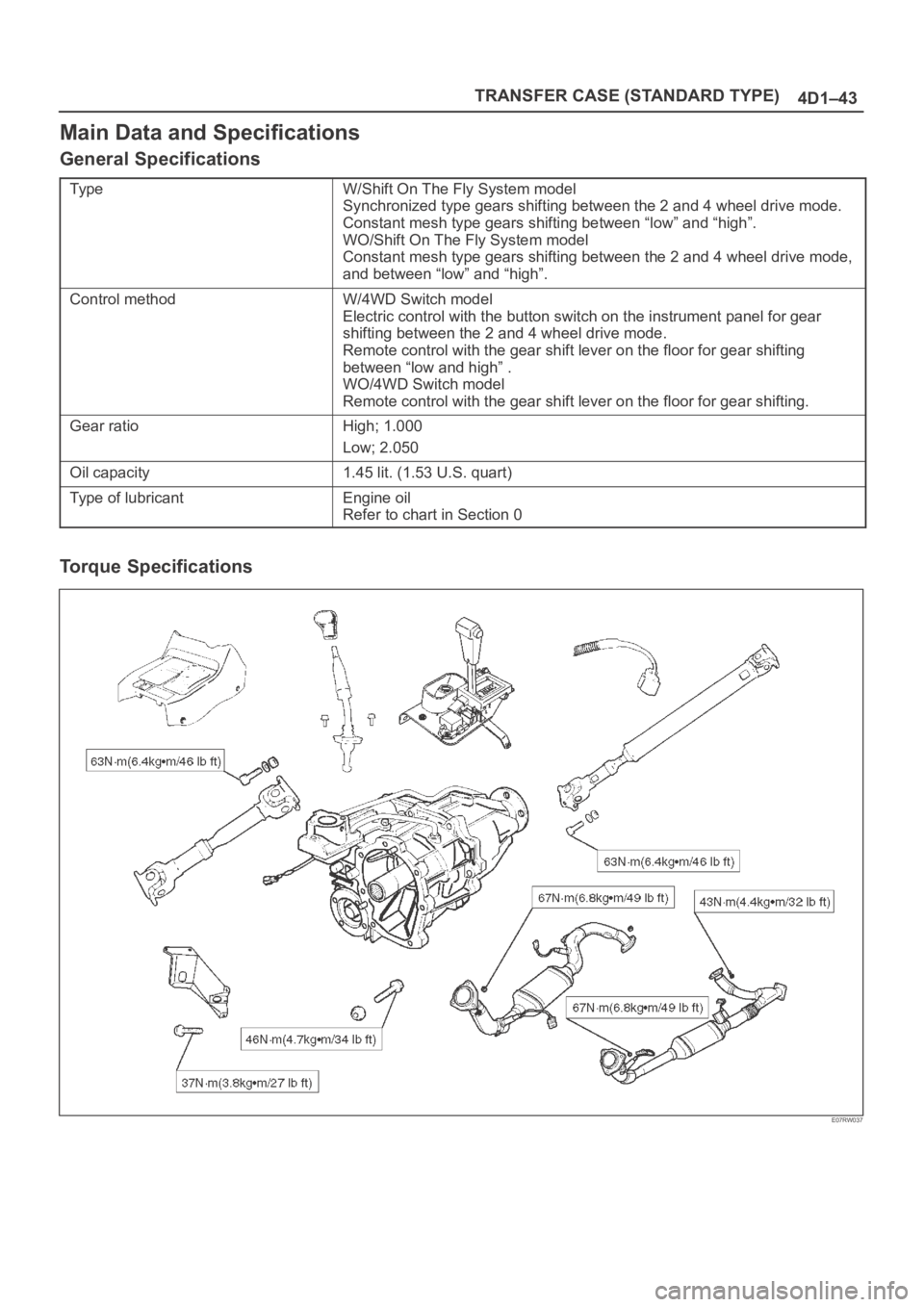
Torque Specifications
E07RW037
Page 1458 of 6000
6E–341 ENGINE DRIVEABILITY AND EMISSIONS
this is done, if the problem still exists, it may be diagnosed
in the normal manner.
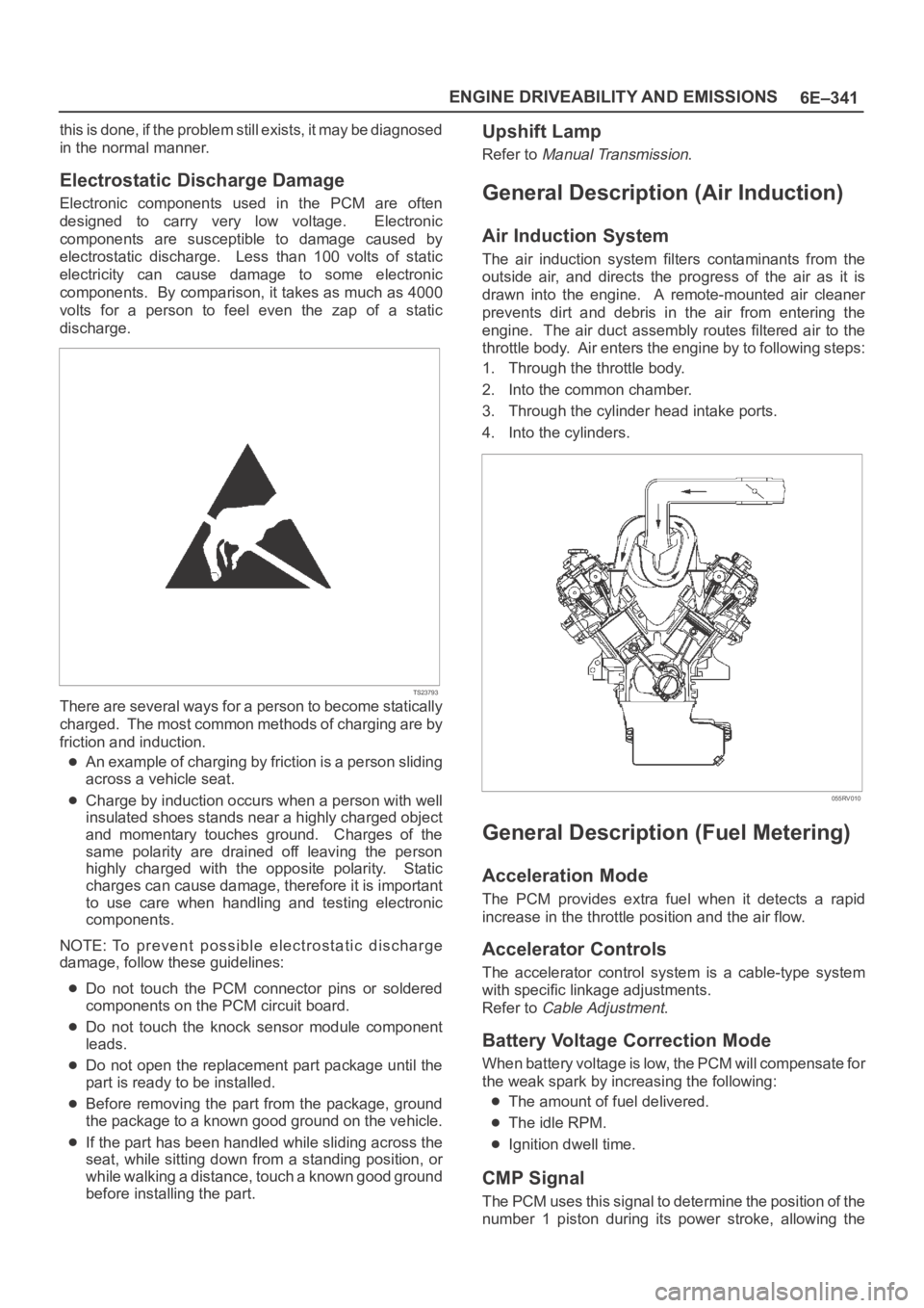
Electrostatic Discharge Damage
Electronic components used in the PCM are often
designed to carry very low voltage. Electronic
components are susceptible to damage caused by
electrostatic discharge. Less than 100 volts of static
electricity can cause damage to some electronic
components. By comparison, it takes as much as 4000
volts for a person to feel even the zap of a static
discharge.
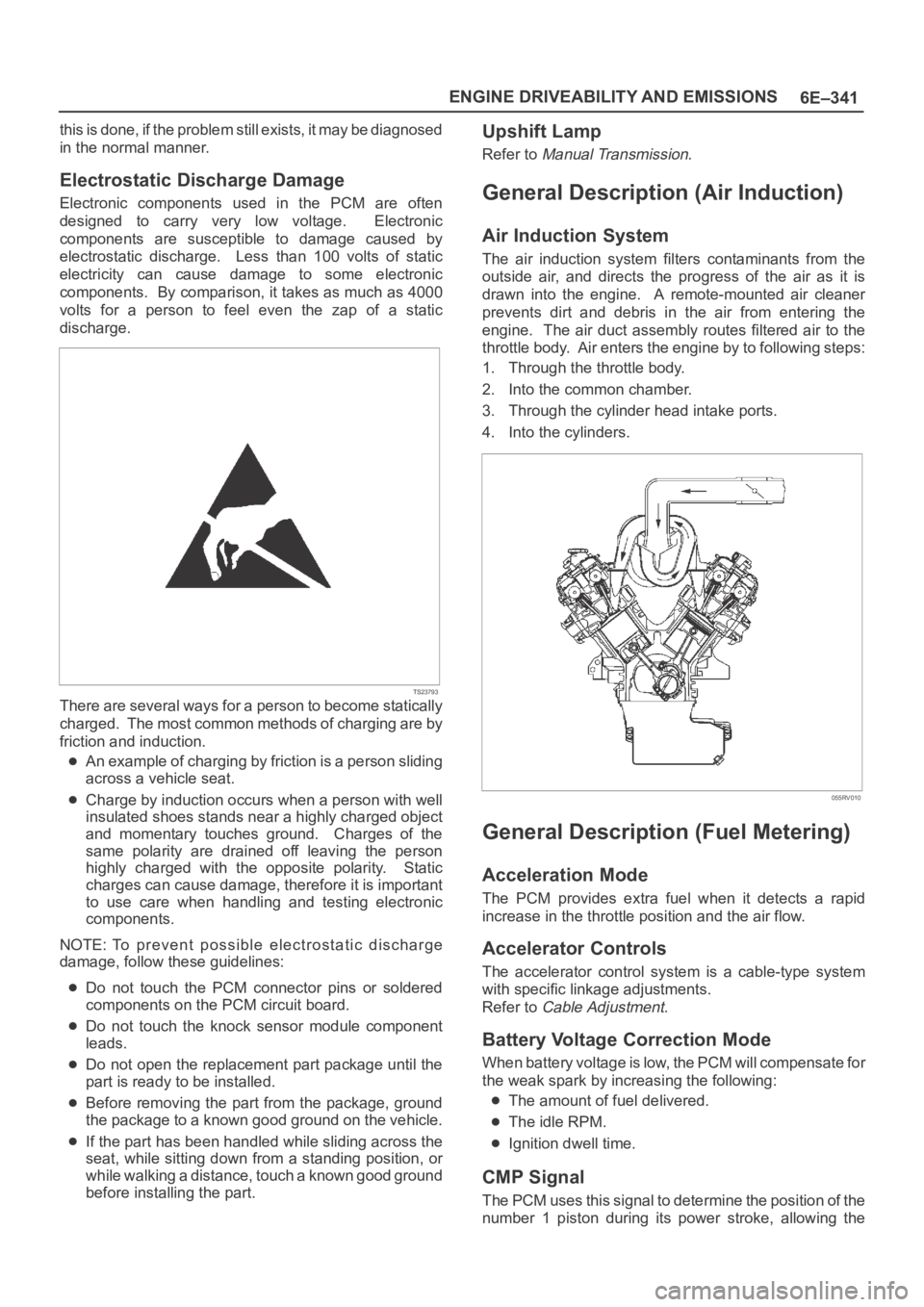
TS23793
There are several ways for a person to become statically
charged. The most common methods of charging are by
friction and induction.
An example of charging by friction is a person sliding
across a vehicle seat.
Charge by induction occurs when a person with well
insulated shoes stands near a highly charged object
and momentary touches ground. Charges of the
same polarity are drained off leaving the person
highly charged with the opposite polarity. Static
charges can cause damage, therefore it is important
to use care when handling and testing electronic
components.
NOTE: To prevent possible electrostatic discharge
damage, follow these guidelines:
Do not touch the PCM connector pins or soldered
components on the PCM circuit board.
Do not touch the knock sensor module component
leads.
Do not open the replacement part package until the
part is ready to be installed.
Before removing the part from the package, ground
the package to a known good ground on the vehicle.
If the part has been handled while sliding across the
seat, while sitting down from a standing position, or
while walking a distance, touch a known good ground
before installing the part.
Upshift Lamp
Refer to Manual Transmission.
General Description (Air Induction)
Air Induction System
The air induction system filters contaminants from the
outside air, and directs the progress of the air as it is
drawn into the engine. A remote-mounted air cleaner
prevents dirt and debris in the air from entering the
engine. The air duct assembly routes filtered air to the
throttle body. Air enters the engine by to following steps:
1. Through the throttle body.
2. Into the common chamber.
3. Through the cylinder head intake ports.
4. Into the cylinders.
055RV010
General Description (Fuel Metering)
Acceleration Mode
The PCM provides extra fuel when it detects a rapid
increase in the throttle position and the air flow.
Accelerator Controls
The accelerator control system is a cable-type system
with specific linkage adjustments.
Refer to
Cable Adjustment.
Battery Voltage Correction Mode
When battery voltage is low, the PCM will compensate for
the weak spark by increasing the following:
The amount of fuel delivered.
The idle RPM.
Ignition dwell time.
CMP Signal
The PCM uses this signal to determine the position of the
number 1 piston during its power stroke, allowing the
Page 1462 of 6000
6E–345 ENGINE DRIVEABILITY AND EMISSIONS
0014
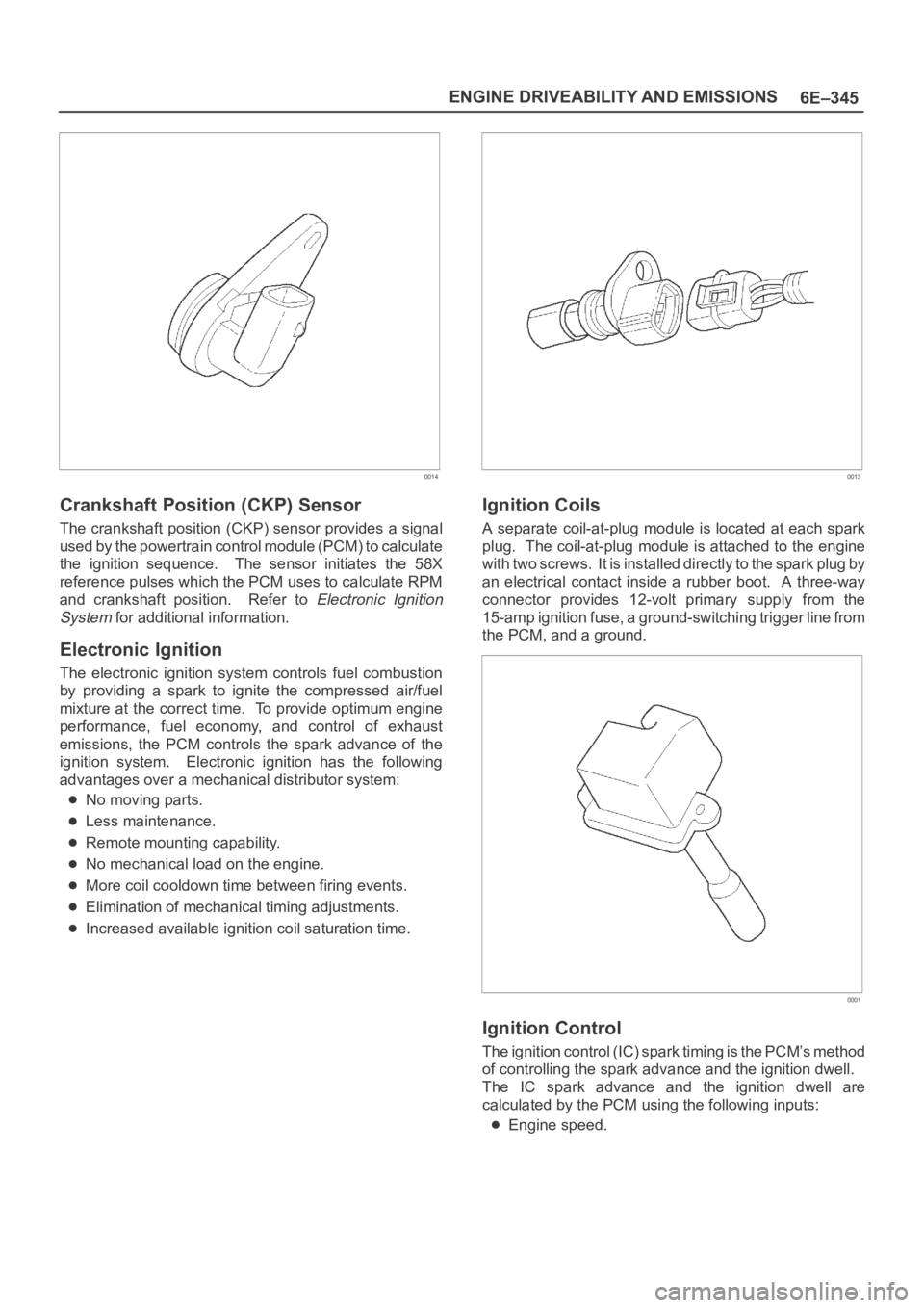
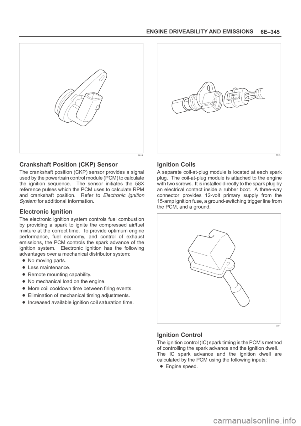
Crankshaft Position (CKP) Sensor
The crankshaft position (CKP) sensor provides a signal
used by the powertrain control module (PCM) to calculate
the ignition sequence. The sensor initiates the 58X
reference pulses which the PCM uses to calculate RPM
and crankshaft position. Refer to
Electronic Ignition
System
for additional information.
Electronic Ignition
The electronic ignition system controls fuel combustion
by providing a spark to ignite the compressed air/fuel
mixture at the correct time. To provide optimum engine
performance, fuel economy, and control of exhaust
emissions, the PCM controls the spark advance of the
ignition system. Electronic ignition has the following
advantages over a mechanical distributor system:
No moving parts.
Less maintenance.
Remote mounting capability.
No mechanical load on the engine.
More coil cooldown time between firing events.
Elimination of mechanical timing adjustments.
Increased available ignition coil saturation time.
0013
Ignition Coils
A separate coil-at-plug module is located at each spark
plug. The coil-at-plug module is attached to the engine
with two screws. It is installed directly to the spark plug by
an electrical contact inside a rubber boot. A three-way
connector provides 12-volt primary supply from the
15-amp ignition fuse, a ground-switching trigger line from
the PCM, and a ground.
0001
Ignition Control
The ignition control (IC) spark timing is the PCM’s method
of controlling the spark advance and the ignition dwell.
The IC spark advance and the ignition dwell are
calculated by the PCM using the following inputs:
Engine speed.
Page 2121 of 6000
6E–228
4JX1–TC ENGINE DRIVEABILITY AND EMISSIONS
General Description (Air Induction)
Air Induction System
The air induction system filters contaminants from the
outside air, and directs the progress of the air as it is
drawn into the engine. A remote-mounted air cleaner
prevents dirt and debris in the air from entering the
engine. The air duct assembly routes filtered air to the
throttle body. Air enters the engine by to following steps:
1. Through the throttle body.
2. Into the intake manifold.
3. Through the cylinder head intake ports.
4. Into the cylinders.
General Description (Fuel Metering)
Deceleration Mode
The ECM reduces the amount of fuel injected when it
detects a decrease in the Accelerator position.
Fuel Injector
Fuel injector comprises the solenoid, hydraulic line, and
fuel line. Fuel injection is controlled by the continuity time
signal and continuity start timing signal from ECM to the
solenoid
ECM determines the running conditions of engine by
input signals such as engine speed. Accelerator throttle
valve opening, and engine coolant temperature, thereby
to send the solenoid the best suited signal to the engine
status. When current is carried to the solenoid, the
armature opens the poppet valve to alow high pressure oil
to run into the injector. Under the pressure of the oil, the
piston and plunger are depressed to compress the fuel in
the combustion chamber of the plunger. Specifically, the
pressure of the fuel compressed is increased by a piston
top/ plunger bottom area ratio over the pressure of high
pressure oil, thereby lifting the fuel nozzle end needle for
injecting fuel.
Fuel Metering System Components
The fuel metering system is made up of the following
parts:
The fuel injectors.
The intake throttle body.
The Accelerator position (AP) sensor
The ECM.
The crankshaft position (CKP) sensor.
The camshaft position (CMP) sensor.
Basic System Operation
Fuel is supplied through fuel filter to the fuel pump.
The fuel pump is installed to the oil pump, and fuel is
forced, through the fuel pump outlet, pipe and cylinder
head inside, into the fuel injector.
An orifice is provided at the rear fuel outlet of cylinder
head to control the pressure of oil.The injector is controlled by ECM which gives
opening/closing commands to the solenoid installed on
the top of the injector. Opening/closing operation of the
pressurized engine oil circuit of the injector controls fuel
injection quantity, fuel injection timing, etc.
A/C Clutch Diagnosis
A/C Request Signal
This signal tells the ECM when the A/C mode is selected
at the A/C control head. The ECM uses this to adjust the
idle speed.
Refer to
A/C Clutch Circuit Diagnosis for A/C wiring
diagrams and diagnosis for A/C electrical system.
General Description Exhaust Gas
Recirculation (EGR) System
EGR Purpose
The exhaust gas recirculation (EGR) system is use to
reduce emission levels of oxides of nitrogen (NOx). NOx
emission levels are caused by a high combustion
temperature. The EGR system lowers the NOx emission
levels by decreasing the combustion temperature.
The ECM uses information from the following sensors to
control EGR valve boost pressure.
ECT
ITP
Engine Speed
AP sensor
Page 2993 of 6000

8D–400 WIRING SYSTEM
ITEM MALFUNCTION POSSIBLE CAUSE DETECTING METHOD REMARKS
Even when door
unlocked with
key, alarm
operates.
Alarm does not
operate even with
tailgate open.
Even when
tailgate is opened
with key, alarm
does not stop.
Even when
engine hood is
opened with
remote release,
alarm does not
operate
Even when
starter switch is
turned, alarm
does not stop
Indicator light
continues
flashingRefer to “Connector
check table” in this
system.
Refer to “Connector
check table” in this
system.
Refer to “Connector
check table” in this
system. Defective contact of detect
switch, or damaged switch wiring.
Door detect switch is assembled
to wrong door.
Defective contact of tailgate
switch, or defective wiring.
Defective contact of tailgate
detect switch, or damage wiring.
Damaged engine hood switch or
wiring.
Defective contact of starter
switch.
Damaged door switch, or a short
circuit in wiring.
Damaged tamper switch, or a
short circuit in wiring.Check the control unit connector.
When key is turned to lock
position, alarm stops.
When luggage room light switch
is turned on with tailgate open,
luggage room light does not
come on.
Check the control unit connector.
With starter switch turned to
“ACC” position, audio, cigarette
lighter and door mirrors (on
“ACC” circuit) do not operate.
After closing door, dome light and
courtesy light remain on.
Check the control unit connector. F
G
H
I
J
K
Page 4304 of 6000
TRANSFER CASE (STANDARD TYPE)
4D1–43
Main Data and Specifications
General Specifications
Ty p eW/Shift On The Fly System model
Synchronized type gears shifting between the 2 and 4 wheel drive mode.
Constant mesh type gears shifting between “low” and “high”.
WO/Shift On The Fly System model
Constant mesh type gears shifting between the 2 and 4 wheel drive mode,
and between “low” and “high”.
Control methodW/4WD Switch model
Electric control with the button switch on the instrument panel for gear
shifting between the 2 and 4 wheel drive mode.
Remote control with the gear shift lever on the floor for gear shifting
between “low and high” .
WO/4WD Switch model
Remote control with the gear shift lever on the floor for gear shifting.
Gear ratioHigh; 1.000
Low; 2.050
Oil capacity1.45 lit. (1.53 U.S. quart)
Type of lubricantEngine oil
Refer to chart in Section 0
Torque Specifications
E07RW037
Page 4998 of 6000
6E–341 ENGINE DRIVEABILITY AND EMISSIONS
this is done, if the problem still exists, it may be diagnosed
in the normal manner.
Electrostatic Discharge Damage
Electronic components used in the PCM are often
designed to carry very low voltage. Electronic
components are susceptible to damage caused by
electrostatic discharge. Less than 100 volts of static
electricity can cause damage to some electronic
components. By comparison, it takes as much as 4000
volts for a person to feel even the zap of a static
discharge.
TS23793
There are several ways for a person to become statically
charged. The most common methods of charging are by
friction and induction.
An example of charging by friction is a person sliding
across a vehicle seat.
Charge by induction occurs when a person with well
insulated shoes stands near a highly charged object
and momentary touches ground. Charges of the
same polarity are drained off leaving the person
highly charged with the opposite polarity. Static
charges can cause damage, therefore it is important
to use care when handling and testing electronic
components.
NOTE: To prevent possible electrostatic discharge
damage, follow these guidelines:
Do not touch the PCM connector pins or soldered
components on the PCM circuit board.
Do not touch the knock sensor module component
leads.
Do not open the replacement part package until the
part is ready to be installed.
Before removing the part from the package, ground
the package to a known good ground on the vehicle.
If the part has been handled while sliding across the
seat, while sitting down from a standing position, or
while walking a distance, touch a known good ground
before installing the part.
Upshift Lamp
Refer to Manual Transmission.
General Description (Air Induction)
Air Induction System
The air induction system filters contaminants from the
outside air, and directs the progress of the air as it is
drawn into the engine. A remote-mounted air cleaner
prevents dirt and debris in the air from entering the
engine. The air duct assembly routes filtered air to the
throttle body. Air enters the engine by to following steps:
1. Through the throttle body.
2. Into the common chamber.
3. Through the cylinder head intake ports.
4. Into the cylinders.
055RV010
General Description (Fuel Metering)
Acceleration Mode
The PCM provides extra fuel when it detects a rapid
increase in the throttle position and the air flow.
Accelerator Controls
The accelerator control system is a cable-type system
with specific linkage adjustments.
Refer to
Cable Adjustment.
Battery Voltage Correction Mode
When battery voltage is low, the PCM will compensate for
the weak spark by increasing the following:
The amount of fuel delivered.
The idle RPM.
Ignition dwell time.
CMP Signal
The PCM uses this signal to determine the position of the
number 1 piston during its power stroke, allowing the
Page 5002 of 6000
6E–345 ENGINE DRIVEABILITY AND EMISSIONS
0014
Crankshaft Position (CKP) Sensor
The crankshaft position (CKP) sensor provides a signal
used by the powertrain control module (PCM) to calculate
the ignition sequence. The sensor initiates the 58X
reference pulses which the PCM uses to calculate RPM
and crankshaft position. Refer to
Electronic Ignition
System
for additional information.
Electronic Ignition
The electronic ignition system controls fuel combustion
by providing a spark to ignite the compressed air/fuel
mixture at the correct time. To provide optimum engine
performance, fuel economy, and control of exhaust
emissions, the PCM controls the spark advance of the
ignition system. Electronic ignition has the following
advantages over a mechanical distributor system:
No moving parts.
Less maintenance.
Remote mounting capability.
No mechanical load on the engine.
More coil cooldown time between firing events.
Elimination of mechanical timing adjustments.
Increased available ignition coil saturation time.
0013
Ignition Coils
A separate coil-at-plug module is located at each spark
plug. The coil-at-plug module is attached to the engine
with two screws. It is installed directly to the spark plug by
an electrical contact inside a rubber boot. A three-way
connector provides 12-volt primary supply from the
15-amp ignition fuse, a ground-switching trigger line from
the PCM, and a ground.
0001
Ignition Control
The ignition control (IC) spark timing is the PCM’s method
of controlling the spark advance and the ignition dwell.
The IC spark advance and the ignition dwell are
calculated by the PCM using the following inputs:
Engine speed.