1998 OPEL FRONTERA bulb
[x] Cancel search: bulbPage 544 of 6000

4B1–11 DRIVE LINE CONTROL SYSTEM (SHIFT ON THE FLY)
Functions of Indicator Lamp
Indication of vehicle condition : Indicator lamp is
controlled by 4WD control unit and shows vehicle
conditions as below.
Indicator
Vehicle condition4WD switchTransfer position
switchFront axle switch
Off2WDOff (Close)2WD (Open)2WD (Open)
On4WDOn (Open)4WD (Close)4WD (Close)
Blink (2Hz)OperatingOn (Open)4WD (Close)2WD (Open)
Off (Close)2WD (Open)4WD (Close)
Blink (4Hz)Stop operatingOn (Open)2WD (Open)2WD (Open)
Off (Close)4WD (Close)4WD (Close)
Bulb check :To check the bulb of indicator lamp, the
indicator lamp comes on when ignition key is turned on,
and goes off when the engine is started.
Retrials from 2WD to 4WD :In cold weather or under
high speed condition, the gear shifting (engagement)sometimes does not complete by 3 trials. In such case,
the indicator lamp inform driver of this incident as
aforementioned chart (shown at Retrial in Outline of shift
on the fly system).
Diagnosis
Before Judging That Troubles Occur
(Unfaulty mode)
When Switching from 2WD to 4WD
1.In case that blinking frequency of the 4WD
indicator changes from 2Hz to 4Hz.
When heavy synchronization load is needed, the
motor actuator tries the shifting transfer gear three
times including the activation shifting. While the
motor actuator tries shifting, the indicator blinks by
2Hz. If the third shifting fails, the indicator’s blinking
changes from 2Hz to 4Hz at the same time that the
motor actuator shifted back to 2WD.
Heavy synchronization load occurs by:
extremely lower temperature.
higher speed, rotation difference of wheels during
cornering.
Solution 1: Operate again after stop the vehicle or
slow down.
2.In case that the 4WD indicator continues blinking
by 2Hz for more than 11.5 seconds.
When there is rotation difference of wheels or there
is phase difference between front wheels and axles,
it is difficult to connect front wheels to front axles. The
blinking by 2Hz shows that shifting the transfer gear
or connecting the front wheels is in the middle of
operating. In above case, the indicator’s blinking by
2Hz shows that connecting the front wheels is not
completed (because the indicator’s blinking changes
to 4Hz when the shifting transfer gear is impossible.).
And removal of rotation or phase difference make
connecting the front wheels possible.
Solution 2: When vehicle is running, drive
straight ahead while accelerating and
decelerating. When vehicle is at a stop, move the
vehicle forward and backward from 2 to 3 meters.When switching from 4WD to 2WD
1.In case that the 4WD indicator continues blinking
by 2Hz .
The 4WD indicator continues blinking by 2Hz until
both shifting the transfer gear and disconnecting the
front wheels are completed when switching 4WD to
2WD. When driveline is loaded with torsional torque,
the shifting transfer gear and disconnecting front
wheels are impossible. In this case, removal of
torsional torque on driveline make the shifting
transfer gear and disconnecting front wheels
possible.
Solution 3: When vehicle is running, drive
straight ahead while accelerating and
decelerating. When vehicle is at a stop, move the
vehicle forward and backward from 2 to 3 meters.
2.In case that the 4WD indicator’s blinking changes
from 2Hz to 4Hz.
Check the position of transfer lever. Is it at “4L”
position? In view of the shifting mechanism of
transfer, the gear shifting from 4WD to 2WD at “4L”
condition is impossible.
Solution 4: Push the 4WD switch to 4WD, shift the
transfer lever to “High” position and re–operate
the 4WD switch to 2WD.
Page 577 of 6000

DRIVE LINE CONTROL SYSTEM (TOD) 4B2–6
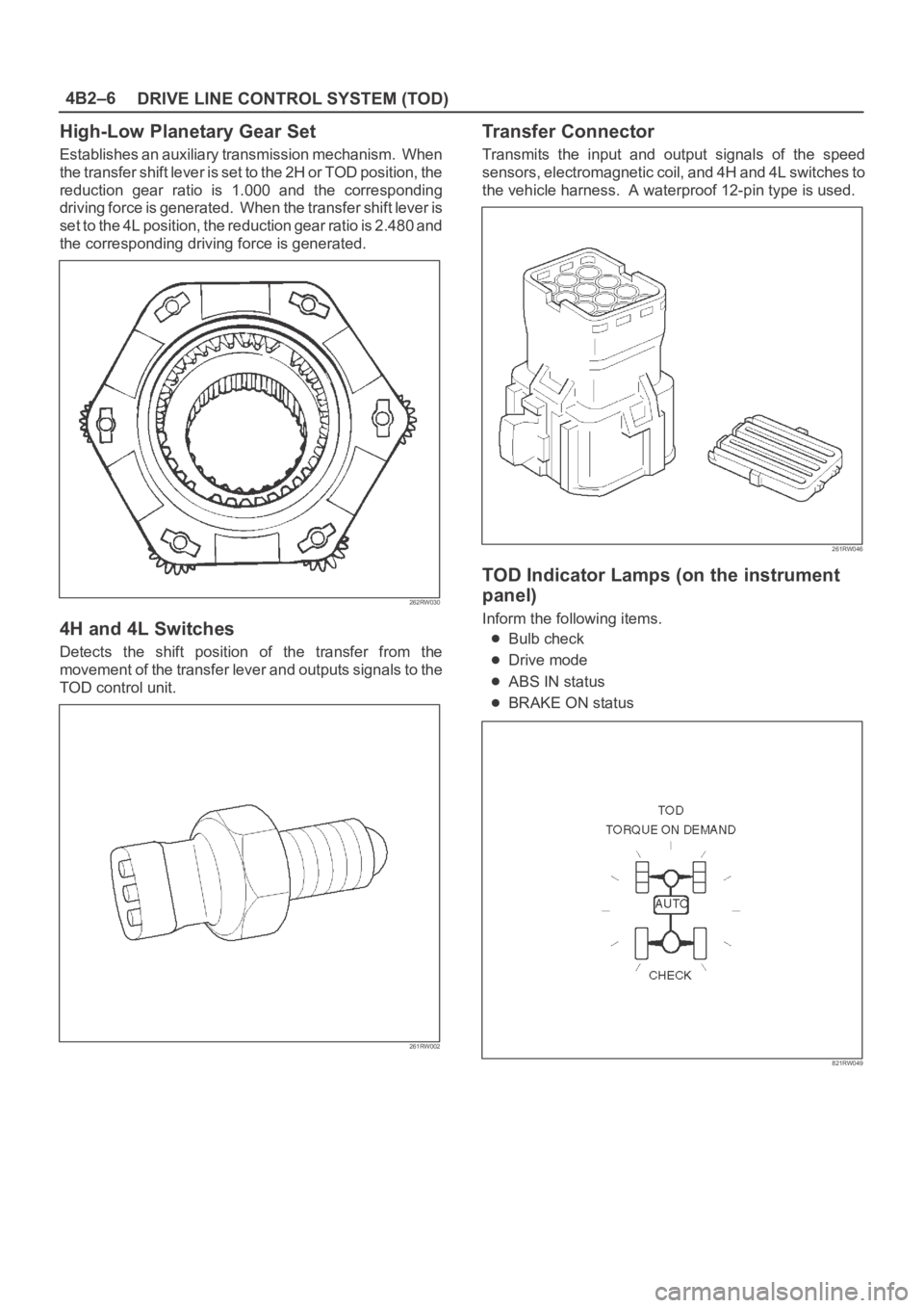
High-Low Planetary Gear Set
Establishes an auxiliary transmission mechanism. When
the transfer shift lever is set to the 2H or TOD position, the
reduction gear ratio is 1.000 and the corresponding
driving force is generated. When the transfer shift lever is
set to the 4L position, the reduction gear ratio is 2.480 and
the corresponding driving force is generated.
262RW030
4H and 4L Switches
Detects the shift position of the transfer from the
movement of the transfer lever and outputs signals to the
TOD control unit.
261RW002
Transfer Connector
Transmits the input and output signals of the speed
sensors, electromagnetic coil, and 4H and 4L switches to
the vehicle harness. A waterproof 12-pin type is used.
261RW046
TOD Indicator Lamps (on the instrument
panel)
Inform the following items.
Bulb check
Drive mode
ABS IN status
BRAKE ON status
821RW049
Page 578 of 6000

4B2–7 DRIVE LINE CONTROL SYSTEM (TOD)
Check Lamp
Inform the following items.
Bulb check
Fail (fail alarm)
Trouble code
Diesel/gasoline MAP
821RW078
TOD ECU
This control unit is mounted to the front right hand seat via
a special bracket.
F07RW029
Page 580 of 6000

4B2–9 DRIVE LINE CONTROL SYSTEM (TOD)
C07RW061
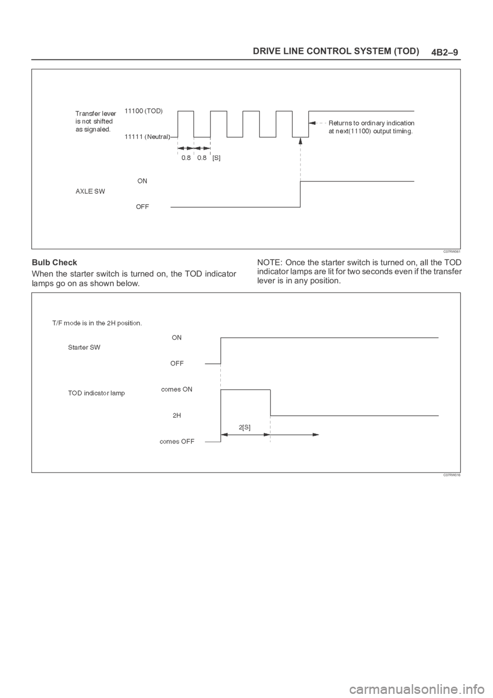
Bulb Check
When the starter switch is turned on, the TOD indicator
lamps go on as shown below.NOTE: Once the starter switch is turned on, all the TOD
indicator lamps are lit for two seconds even if the transfer
lever is in any position.
C07RW016
Page 581 of 6000

DRIVE LINE CONTROL SYSTEM (TOD) 4B2–10
Simplified checking method of ABS IN and BRAKE ON signals:
In the event that any of the signal inputs listed below are
observed while the self-diagnostic code is being
displayed (the self-diagnostic connector is short-circuited
to GND), you can simply check the ABS IN and BRAKE
ON signals as shown in the figures below.
C07RW017
Check Lamp
Check Lamp Valve Check
When the starter switch is turned on in the normal state,
the control unit turns on the CHECK lamp to check the
bulb.
C07RW019
Page 635 of 6000

DRIVE LINE CONTROL SYSTEM (TOD) 4B2–64
StepActionYe sNo
1When the 4WD SW is selected to the 4WD position, is 0 V
observed between terminal 12 and 19?
Go to Step 2
Repair the 4WD
SW circuit.
Go to Step 7
2When the 4WD SW is selected to the 2WD position, is 12 V
observed between terminals 12 and 19?
Go to Step 3
Repair the 4WD
SW circuit.
Go to Step 7
31. Disconnect the ECU connector.
Is the continuity established between terminals (B–67)1 and
(B–68)13?
Go to Step 4
Replace TOD
indicator lamp
bulb.
Go to Step 7
4Is the continuity established between terminals (B–67)1 and
(B–68)14?
Go to Step 5
Replace TOD
indicator lamp
bulb.
Go to Step 7
5Is the continuity established between terminals (B–67)1 and
(B–68)15?
Go to Step 6
Replace TOD
indicator lamp
bulb.
Go to Step 7
6Is the continuity established between terminals (B–67)1 and
(B–68)16?
Replace ECU.
Go to Step 7
Replace TOD
indicator lamp
bulb.
Go to Step 7
7Check that all the parts are mounted.
Is this step complete?Repeat the
“Diagnosis Flow”.
Return to Step 7
Page 640 of 6000

4B2–69 DRIVE LINE CONTROL SYSTEM (TOD)
StepActionYe sNo
1When the transfer lever is shifted to the High position, is 5V
observed between terminals 8 and 19 (4H switch)?
Go to Step 2Go to Step 14
2When the transfer lever is shifted to the neutral position, is 0V
observed between terminals 8 and 19 (4H switch)?
Go to Step 3Go to Step 14
3When the transfer lever is shifted to the 4L position, is 5V
observed between terminals 8 and 19 (4H switch)?
Go to Step 4Go to Step 14
41. Turn off the starter switch.
Is the continuity established between terminals 1 and 25?
Go to Step 5
Replace TOD
indcator lamp
bulb.
Go to Step 23
5Is the continuity established between terminals 1 and 26?
Go to Step 6
Replace TOD
indicator lamp
bulb.
Go to Step 23
6Is the continuity established between terminals 1 and 27?
Go to Step 7
Replace TOD
indicator lamp
bulb.
Go to Step 23
7Is the continuity established between terminals 1 and 28?
Go to Step 8
Replace TOD
indicator lamp
bulb.
Go to Step 23
8Is the continuity established between terminals 1 and 29?
Go to Step 9
Replace TOD
indicator lamp
bulb.
Go to Step 23
91. Turn on the starter switch.
2. Shift the transfer lever is shifted to the 4L position.
Is 0 V observed between terminals 25 and 20?
Go to Step 10
The ECU has
failed. Replace
the ECU.
Go to Step 23
10Is 0 V observed between terminals 26 and 20?
Go to Step 11
The ECU has
failed. Replace
the ECU.
Go to Step 23
11Is 0 V observed between terminals 27 and 20?
Go to Step 12
The ECU has
failed. Replace
the ECU.
Go to Step 23
12Is 12 V observed between terminals 28 and 20?
Go to Step 13
The ECU has
failed. Replace
the ECU.
Go to Step 23
13Is 0 V observed between terminals 29 and 20?The phenomenon
is not
reproduced.
Refer to
“Troubles
intermittently
observed”.
Go to Step 23
The ECU has
failed. Replace
the ECU.
Go to Step 23
Page 853 of 6000

5A–43 BRAKE CONTROL SYSTEM
Chart B-1 With the key in the ON position (Before starting the engine). Warning light (W/L)
is not activated.
StepActionYe sNo
1Is W/L fuse C-10 disconnected?Replace fuse.
Go to Step 5
Go to Step 2
2Is W/L burnt out?Replace W/L
bulb.
Go to Step 5
Go to Step 3
31. Turn the key off.
2. Disconnect EHCU connector.
3. Turn the key ON.
4. Measure the voltage between EHCU connector terminal 13
and 14.
Is the voltage equal to the battery voltage?
Go to Step 4
Repair harness
and connector.
Go to Step 5
4Is there continuity between EHCU connector terminals, 12 and 15
and body ground.Check harness
for suspected
disconnection.
No fault found:
Replace EHCU.
Go to Step 5
Repair harness
and connector.
Go to Step 5
5Reconnect all components, ensure all components are properly
mounted.
Was this step finished?Repeat the “Basic
diagnostic flow
chart.”
Go to Step 5
Chart B-2 EHCU Abnormality (DTC 14)
StepActionYe sNo
11. Turn the key off.
2. Disconnect the EHCU connector.
3. Inspect EHCU ground.
Is there resistance between the EHCU connector terminals, 12
and 15 and body ground?
Go to Step 2
Repair the body
ground harness.
Go to Step 3
21. Turn the key off, connect the EHCU.
2. Erase the trouble code.
3. Turn Ignition off, then on, to perform system self-check.
4. If warning light remains on, display trouble codes once again.
Is the check trouble code 14?
Replace EHCU.
Go to Step 3
Inspect in
accordance with
the DTC
displayed.
31. Reconnect all components and ensure all components are
properly mounted.
2. Clear diagnostic trouble code.
Was this step finished?
Repeat the “Basic
diagnostic flow
chart.”
Go to Step 3