1998 OPEL FRONTERA bulb
[x] Cancel search: bulbPage 4698 of 6000
6E–41 ENGINE DRIVEABILITY AND EMISSIONS
If the MIL was set by either a fuel trim or misfire-related
DTC, additional requirements must be met. In addition to
the requirements stated in the previous paragraph, these
requirements are as follows:
The diagnostic tests that are passed must occur with
375 RPM of the RPM data stored at the time the last
test failed.
Plus or minus ten (10) percent of the engine load that
was stored at the time the last failed.
Similar engine temperature conditions (warmed up or
warming up ) as those stored at the time the last test
failed.
Meeting these requirements ensures that the fault which
turned on the MIL has been corrected.
The MIL (“Check Engine” lamp) is on the instrument
panel and has the following function:
It informs the driver that a fault affects vehicle emission
levels has occurred and that the vehicle should be
taken for service as soon as possible.
As a bulb and system check, the MIL will come “ON”
with the key “ON” and the engine not running. When
the engine is started, the MIL will turn “OFF.”
When the MIL remains “ON” while the engine is
running, or when a malfunction is suspected due to a
driveability or emissions problem, a Powertrain
On-Board Diagnostic (OBD ll) System Check must be
performed. The procedures for these checks are given
in On-Board Diagnostic (OBD) System Check. These
checks will expose faults which may not be detected if
other diagnostics are performed first.
DTC Types
Each DTC is directly related to a diagnostic test. The
Diagnostic Management System sets DTC based on the
failure of the tests during a trip or trips. Certain tests must
fail two (2) consecutive trips before the DTC is set. The
following are the four (4) types of DTCs and the
characteristics of those codes:
Ty p e A
Emissions related
Requests illumination of the MIL of the first trip with a
fail
Stores a History DTC on the first trip with a fail
Stores a Freeze Frame (if empty)
Stores a Fail Record
Updates the Fail Record each time the diagnostic
test fails
Ty p e B
Emissions related
“Armed” after one (1) trip with a fail
“Disarmed” after one (1) trip with a pass
Requests illumination of the MIL on the second
consecutive trip
with a fail
Stores a History DTC on the second consecutive trip
with a fail (The DTC will be armed after the first fail)
Stores a Freeze Frame on the second consecutive
trip with a fail (if empty)
Stores a Fail Record when the first test fails (not
dependent on
consecutive trip fails)
Updates the Fail Record each time the diagnostic
test fails
Type C (if the vehicle is so equipped)
Non-Emissions related
Requests illumination of the Service Lamp or the
service message on the Drive Information Center
(DIC) on the
first trip with a fail
Stores a History DTC on the first trip with a fail
Does not store a Freeze Frame
Stores Fail Record when test fails
Updates the Fail Record each time the diagnostic
test fails
Type D (Ty p e D non-emissions related are not utilized
on certain vehicle applications).
Non-Emissions related
Dose not request illumination of any lamp
Stores a History DTC on the first trip with a fail
Does not store a Freeze Frame
Stores Fail Record when test fails
Updates the Fail Record each time the diagnostic
test fails
IMPORTANT:Only four Fail Records can be stored.
Each Fail Record is for a different DTC. It is possible that
there will not be Fail Records for every DTC if multiple
DTCs are set.
Storing and Erasing Freeze Frame Data and Failure
Records
The data captured is called Freeze Frame data. The
Freeze Frame data is very similar to a single record of
operating conditions. Whenever the MIL is illuminated,
the corresponding record of operating conditions is
recorded to the Freeze Frame buffer.
Data from these faults take precedence over data
associated with any other fault. The Freeze Frame data
will not be erased unless the associated history DTC is
cleared.
Each time a diagnostic test reports a failure, the current
engine operating conditions are recorded in the
Failure
Records
buffer. A subsequent failure will update the
recorded operating conditions. The following operating
conditions for the diagnostic test which failed
typically
include the following parameters:
Air Fuel Ratio
Air Flow Rate
Fuel Trim
Engine Speed
Engine Load
Engine Coolant Temperature
Vehicle Speed
TP Angle
MAP/BARO
Injector Base Pulse Width
Loop Status
Page 4731 of 6000
6E–74
ENGINE DRIVEABILITY AND EMISSIONS
No Malfunction Indicator Lamp (MIL)
D06RW00006
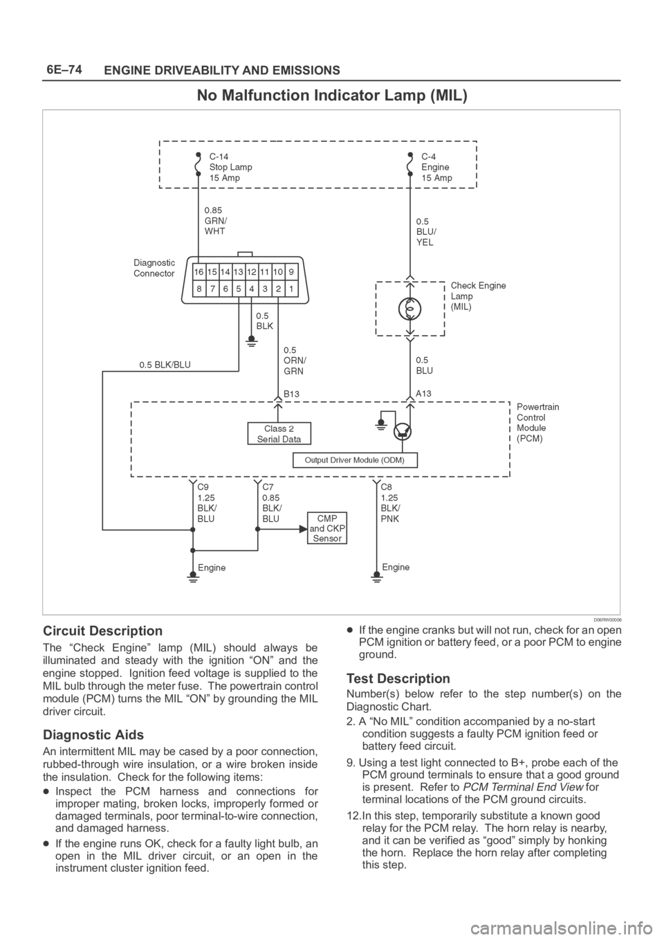
Circuit Description
The “Check Engine” lamp (MIL) should always be
illuminated and steady with the ignition “ON” and the
engine stopped. Ignition feed voltage is supplied to the
MIL bulb through the meter fuse. The powertrain control
module (PCM) turns the MIL “ON” by grounding the MIL
driver circuit.
Diagnostic Aids
An intermittent MIL may be cased by a poor connection,
rubbed-through wire insulation, or a wire broken inside
the insulation. Check for the following items:
Inspect the PCM harness and connections for
improper mating, broken locks, improperly formed or
damaged terminals, poor terminal-to-wire connection,
and damaged harness.
If the engine runs OK, check for a faulty light bulb, an
open in the MIL driver circuit, or an open in the
instrument cluster ignition feed.
If the engine cranks but will not run, check for an open
PCM ignition or battery feed, or a poor PCM to engine
ground.
Test Description
Number(s) below refer to the step number(s) on the
Diagnostic Chart.
2. A “No MIL” condition accompanied by a no-start
condition suggests a faulty PCM ignition feed or
battery feed circuit.
9. Using a test light connected to B+, probe each of the
PCM ground terminals to ensure that a good ground
is present. Refer to
PCM Terminal End View for
terminal locations of the PCM ground circuits.
12.In this step, temporarily substitute a known good
relay for the PCM relay. The horn relay is nearby,
and it can be verified as “good” simply by honking
the horn. Replace the horn relay after completing
this step.
Page 4955 of 6000
6E–298
ENGINE DRIVEABILITY AND EMISSIONS
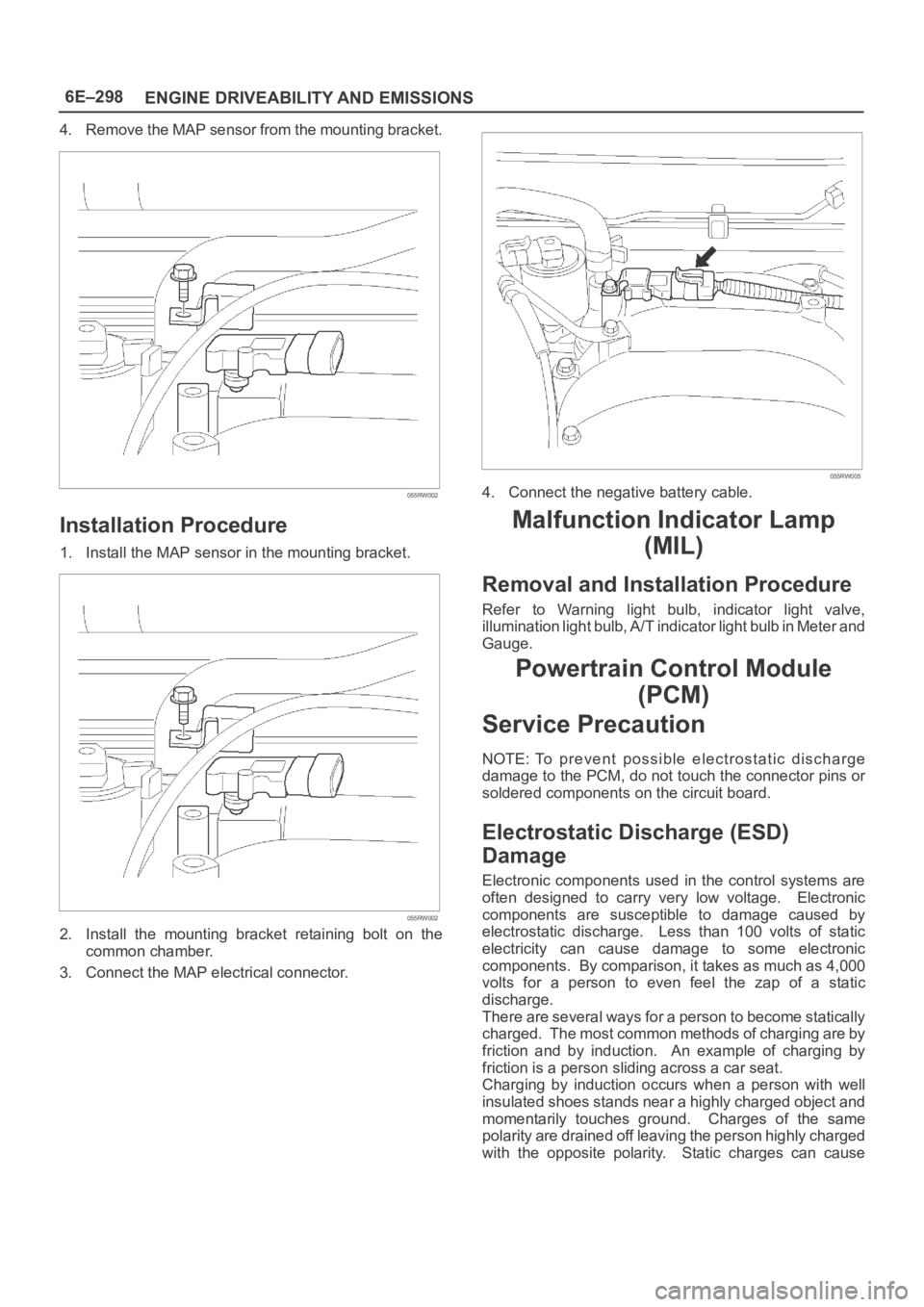
4. Remove the MAP sensor from the mounting bracket.
055RW002
Installation Procedure
1. Install the MAP sensor in the mounting bracket.
055RW002
2. Install the mounting bracket retaining bolt on the
common chamber.
3. Connect the MAP electrical connector.
055RW005
4. Connect the negative battery cable.
Malfunction Indicator Lamp
(MIL)
Removal and Installation Procedure
Refer to Warning light bulb, indicator light valve,
illumination light bulb, A/T indicator light bulb in Meter and
Gauge.
Powertrain Control Module
(PCM)
Service Precaution
NOTE: To prevent possible electrostatic discharge
damage to the PCM, do not touch the connector pins or
soldered components on the circuit board.
Electrostatic Discharge (ESD)
Damage
Electronic components used in the control systems are
often designed to carry very low voltage. Electronic
components are susceptible to damage caused by
electrostatic discharge. Less than 100 volts of static
electricity can cause damage to some electronic
components. By comparison, it takes as much as 4,000
volts for a person to even feel the zap of a static
discharge.
There are several ways for a person to become statically
charged. The most common methods of charging are by
friction and by induction. An example of charging by
friction is a person sliding across a car seat.
Charging by induction occurs when a person with well
insulated shoes stands near a highly charged object and
momentarily touches ground. Charges of the same
polarity are drained off leaving the person highly charged
with the opposite polarity. Static charges can cause
Page 5473 of 6000
6E–44
4JX1–TC ENGINE DRIVEABILITY AND EMISSIONS
No Malfunction Indicator Lamp (MIL)
060RW136
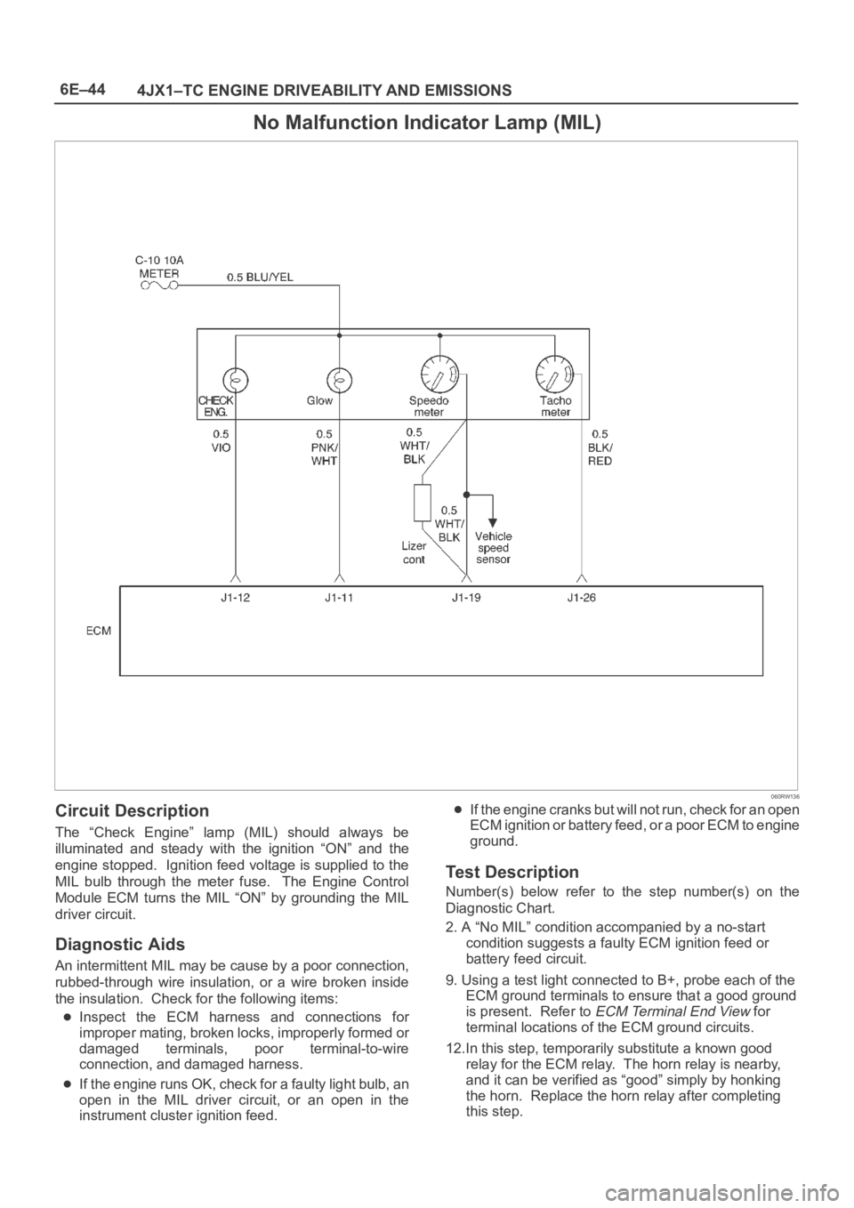
Circuit Description
The “Check Engine” lamp (MIL) should always be
illuminated and steady with the ignition “ON” and the
engine stopped. Ignition feed voltage is supplied to the
MIL bulb through the meter fuse. The Engine Control
Module ECM turns the MIL “ON” by grounding the MIL
driver circuit.
Diagnostic Aids
An intermittent MIL may be cause by a poor connection,
rubbed-through wire insulation, or a wire broken inside
the insulation. Check for the following items:
Inspect the ECM harness and connections for
improper mating, broken locks, improperly formed or
damaged terminals, poor terminal-to-wire
connection, and damaged harness.
If the engine runs OK, check for a faulty light bulb, an
open in the MIL driver circuit, or an open in the
instrument cluster ignition feed.
If the engine cranks but will not run, check for an open
ECM ignition or battery feed, or a poor ECM to engine
ground.
Test Description
Number(s) below refer to the step number(s) on the
Diagnostic Chart.
2. A “No MIL” condition accompanied by a no-start
condition suggests a faulty ECM ignition feed or
battery feed circuit.
9. Using a test light connected to B+, probe each of the
ECM ground terminals to ensure that a good ground
is present. Refer to
ECM Terminal End View for
terminal locations of the ECM ground circuits.
12.In this step, temporarily substitute a known good
relay for the ECM relay. The horn relay is nearby,
and it can be verified as “good” simply by honking
the horn. Replace the horn relay after completing
this step.
Page 5558 of 6000
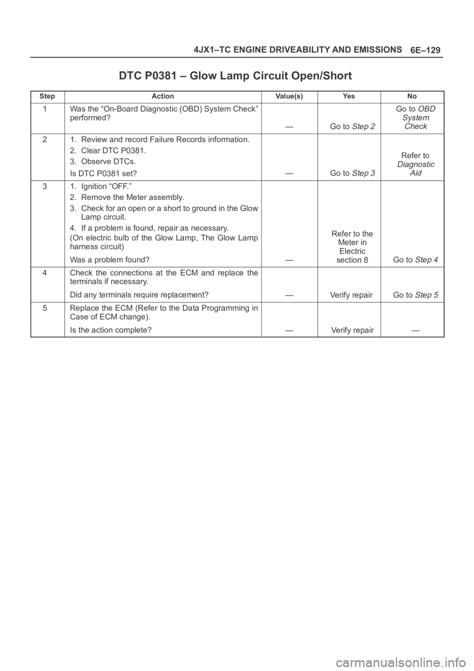
6E–129 4JX1–TC ENGINE DRIVEABILITY AND EMISSIONS
DTC P0381 – Glow Lamp Circuit Open/Short
StepActionVa l u e ( s )Ye sNo
1Was the “On-Board Diagnostic (OBD) System Check”
performed?
—Go to Step 2
Go to OBD
System
Check
21. Review and record Failure Records information.
2. Clear DTC P0381.
3. Observe DTCs.
Is DTC P0381 set?
—Go to Step 3
Refer to
Diagnostic
Aid
31. Ignition “OFF.”
2. Remove the Meter assembly.
3. Check for an open or a short to ground in the Glow
Lamp circuit.
4. If a problem is found, repair as necessary.
(On electric bulb of the Glow Lamp, The Glow Lamp
harness circuit)
Was a problem found?
—
Refer to the
Meter in
Electric
section 8
Go to Step 4
4Check the connections at the ECM and replace the
terminals if necessary.
Did any terminals require replacement?
—Verify repair Go to Step 5
5Replace the ECM (Refer to the Data Programming in
Case of ECM change).
Is the action complete?
—Verify repair—
Page 5596 of 6000
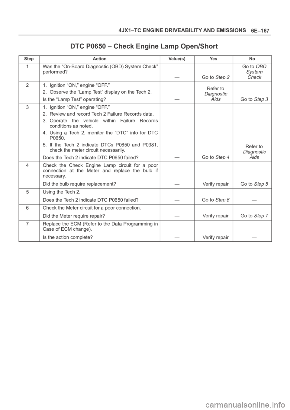
6E–167 4JX1–TC ENGINE DRIVEABILITY AND EMISSIONS
DTC P0650 – Check Engine Lamp Open/Short
StepActionVa l u e ( s )Ye sNo
1Was the “On-Board Diagnostic (OBD) System Check”
performed?
—Go to Step 2
Go to OBD
System
Check
21. Ignition “ON,” engine “OFF.”
2. Observe the “Lamp Test” display on the Tech 2.
Is the “Lamp Test” operating?
—
Refer to
Diagnostic
Aids
Go to Step 3
31. Ignition “ON,” engine “OFF.”
2. Review and record Tech 2 Failure Records data.
3. Operate the vehicle within Failure Records
conditions as noted.
4. Using a Tech 2, monitor the “DTC” info for DTC
P0650.
5. If the Tech 2 indicate DTCs P0650 and P0381,
check the meter circuit necessarily.
Does the Tech 2 indicate DTC P0650 failed?
—Go to Step 4
Refer to
Diagnostic
Aids
4Check the Check Engine Lamp circuit for a poor
connection at the Meter and replace the bulb if
necessary.
Did the bulb require replacement?
—Verify repairGo to Step 5
5Using the Tech 2.
Does the Tech 2 indicate DTC P0650 failed?
—Go to Step 6—
6Check the Meter circuit for a poor connection.
Did the Meter require repair?
—Verify repairGo to Step 7
7Replace the ECM (Refer to the Data Programming in
Case of ECM change).
Is the action complete?
—Verify repair—
Page 5625 of 6000
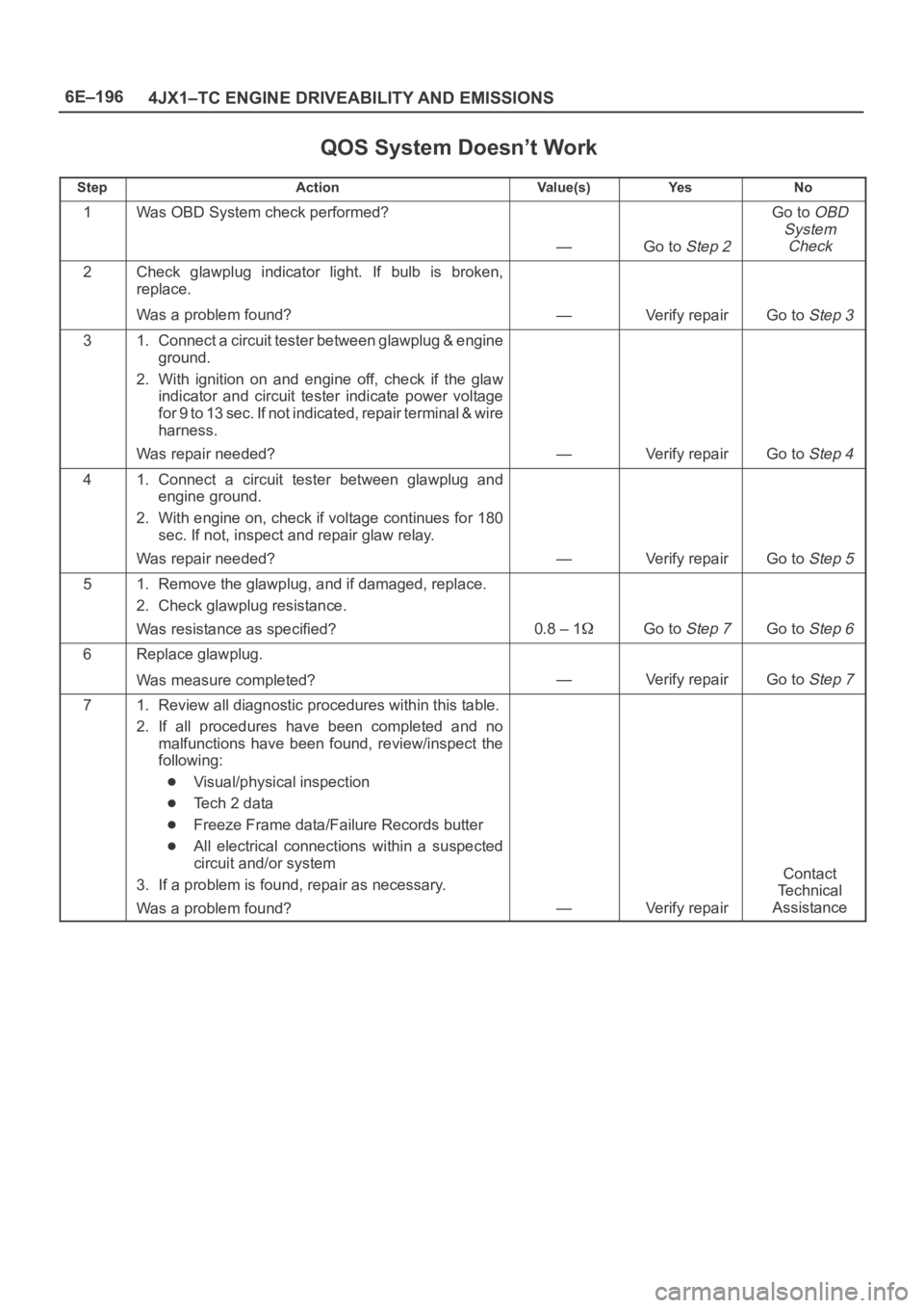
6E–196
4JX1–TC ENGINE DRIVEABILITY AND EMISSIONS
QOS System Doesn’t Work
StepActionVa l u e ( s )Ye sNo
1Was OBD System check performed?
—Go to Step 2
Go to OBD
System
Check
2Check glawplug indicator light. If bulb is broken,
replace.
Was a problem found?
—Verify repairGo to Step 3
31. Connect a circuit tester between glawplug & engine
ground.
2. With ignition on and engine off, check if the glaw
indicator and circuit tester indicate power voltage
for 9 to 13 sec. If not indicated, repair terminal & wire
harness.
Was repair needed?
—Verify repairGo to Step 4
41. Connect a circuit tester between glawplug and
engine ground.
2. With engine on, check if voltage continues for 180
sec. If not, inspect and repair glaw relay.
Was repair needed?
—Verify repairGo to Step 5
51. Remove the glawplug, and if damaged, replace.
2. Check glawplug resistance.
Was resistance as specified?
0.8 – 1Go to Step 7Go to Step 6
6Replace glawplug.
Was measure completed?
—Verify repairGo to Step 7
71. Review all diagnostic procedures within this table.
2. If all procedures have been completed and no
malfunctions have been found, review/inspect the
following:
Visual/physical inspection
Te c h 2 d a t a
Freeze Frame data/Failure Records butter
All electrical connections within a suspected
circuit and/or system
3. If a problem is found, repair as necessary.
Was a problem found?
—Verify repair
Contact
Te c h n i c a l
Assistance