Page 217 of 6000
Ignition swich
"ON"
Time
Blower voltage to turn
on the cooling
7 SEC maximum3 SEC
100%
(MAX HI)
33.5%
(LO)5.32%/S
C06RY00001
33.5%
(LO)
2.63%/S
Mode
DEF
Auto
Mode
100%
(MAX HI)
Ignition
switch "ON"
Thermo Unit 58
C(Gasoline)
52C(Diesel) Time
840RY00009
Page 545 of 6000
4B1–12
DRIVE LINE CONTROL SYSTEM (SHIFT ON THE FLY)
Parts Location (LHD / Diesel Engine Model)
D08RW852
Legend
(1) I–12
(2) I–9
(3) H–7, H–8, H–24, H–25
(4) Fuse Box
(5) C–16
(6) C–94
(7) H–4, H–5(8) P–17
(9) P–18
(10) P–19
(11) H–60
(12) Relay & Fuse Box
(13) H–12, H–16
(14) E–21
(15) E–45
Page 547 of 6000
4B1–14
DRIVE LINE CONTROL SYSTEM (SHIFT ON THE FLY)
Parts Location (RHD / Diesel Engine Model)
D08RW831
Legend
(1) I–9
(2) I–12
(3) E–45
(4) E–21
(5) H–7, H–9
(6) C–16
(7) C–94(8) H–4, H–5
(9) P–17
(10) P–18
(11) P–19
(12) H–60
(13) Relay & Fuse Box
(14) H–15, H–16, H–25, H–26, H–27
(15) Fuse Box
Page 550 of 6000
4B1–17 DRIVE LINE CONTROL SYSTEM (SHIFT ON THE FLY)
Wiring Diagram (LHD / Diesel Engine Model)
D08RW841
Page 553 of 6000
4B1–20
DRIVE LINE CONTROL SYSTEM (SHIFT ON THE FLY)
Wiring Diagram (RHD / Diesel Engine Model)
D08RW842
Page 578 of 6000
4B2–7 DRIVE LINE CONTROL SYSTEM (TOD)
Check Lamp
Inform the following items.
Bulb check
Fail (fail alarm)
Trouble code
Diesel/gasoline MAP
821RW078
TOD ECU
This control unit is mounted to the front right hand seat via
a special bracket.
F07RW029
Page 582 of 6000

4B2–11 DRIVE LINE CONTROL SYSTEM (TOD)
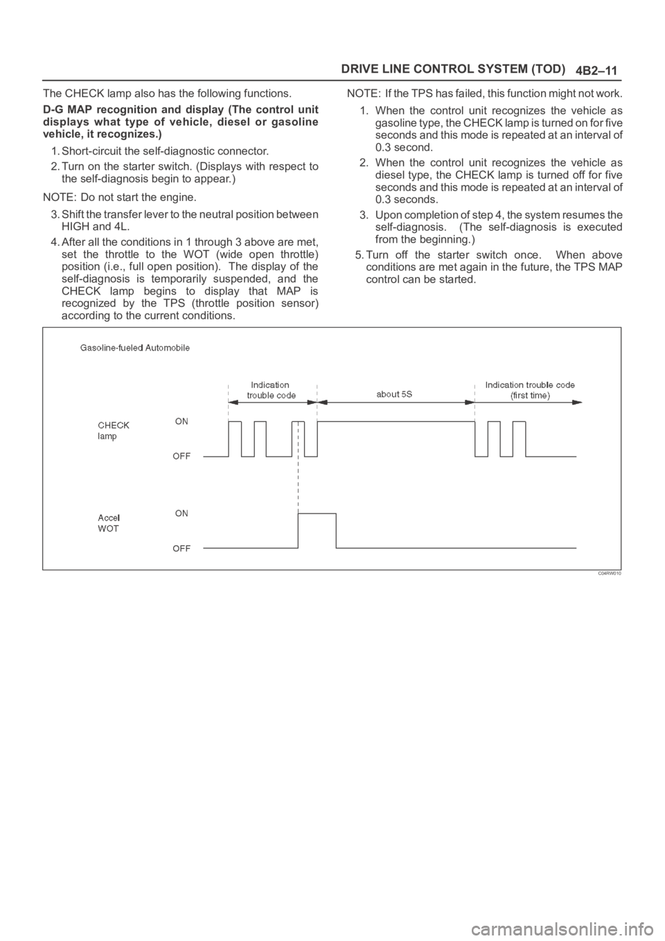
The CHECK lamp also has the following functions.
D-G MAP recognition and display (The control unit
displays what type of vehicle, diesel or gasoline
vehicle, it recognizes.)
1. Short-circuit the self-diagnostic connector.
2. Turn on the starter switch. (Displays with respect to
the self-diagnosis begin to appear.)
NOTE: Do not start the engine.
3. Shift the transfer lever to the neutral position between
HIGH and 4L.
4. After all the conditions in 1 through 3 above are met,
set the throttle to the WOT (wide open throttle)
position (i.e., full open position). The display of the
self-diagnosis is temporarily suspended, and the
CHECK lamp begins to display that MAP is
recognized by the TPS (throttle position sensor)
according to the current conditions.NOTE: If the TPS has failed, this function might not work.
1. When the control unit recognizes the vehicle as
gasoline type, the CHECK lamp is turned on for five
seconds and this mode is repeated at an interval of
0.3 second.
2. When the control unit recognizes the vehicle as
diesel type, the CHECK lamp is turned off for five
seconds and this mode is repeated at an interval of
0.3 seconds.
3. Upon completion of step 4, the system resumes the
self-diagnosis. (The self-diagnosis is executed
from the beginning.)
5. Turn off the starter switch once. When above
conditions are met again in the future, the TPS MAP
control can be started.
C04RW010
Page 615 of 6000
DRIVE LINE CONTROL SYSTEM (TOD) 4B2–44
Check flowTrouble codePhenomenonStandard
834The diesel/gasoline engine identifi-
cation signal is faulty.Gasoline: Continuity established
The engine identification signals of 6VE1 and 4JX1 are
changed each other.
D04RW056