1998 OPEL FRONTERA balance shaft
[x] Cancel search: balance shaftPage 282 of 6000

14. Attach the compressor to the J-34992 holding
fixture and mount the compressor in a vise so that
the compressor will be in a horizontal position and
the shaft can be turned with a wrench.
15. Using a wrench, rotate the compressor crankshaft
or drive plate hub ten complete revolutions at a
speed of approximately one-revolution per second
turning the compressor at less than one-revolution
per second can result in a lower pump-up pressure
and disqualify a good pumping compressor.
16. Observe the reading on high-pressure gauge at the
completion of the tenth revolution of the
compressor. The pressure reading for a good
pumping compressor should be 690 kPa (100 psi)
or above. A pressure reading of less than 620 kPa
(90 psi) would indicate one or more suction and/or
discharge valves leaking an internal leak, or an
inoperative valve, and the refrigerant must be
recovered and the compressor disassembled and
checked for cause of leak. Repair as needed,
reassemble and repeat the pump-up test. Externally
leak test.
17. When the pressure pump-up test is completed,
recover the refrigerant from the high-side and
remove the test plate J-39893.
18. Tilt the compressor so that the compressor suction
and discharge ports are down. Drain the PAG
lubricant from the compressor.
19. Allow the compressor to drain for 10 minutes, then
refill with the proper amount of PAG lubricant, per
oil balance procedure described previously. The
PAG lubricant may be poured into the suction port.
If further assembly or processing is required, a
shipping plate or test plate J-39893 should be
installed to keep out air, dirt and moisture until the
compressor is installed.
Page 439 of 6000

DIFFERENTIAL (FRONT) 4A1–2
Front Drive Axle
Diagnosis
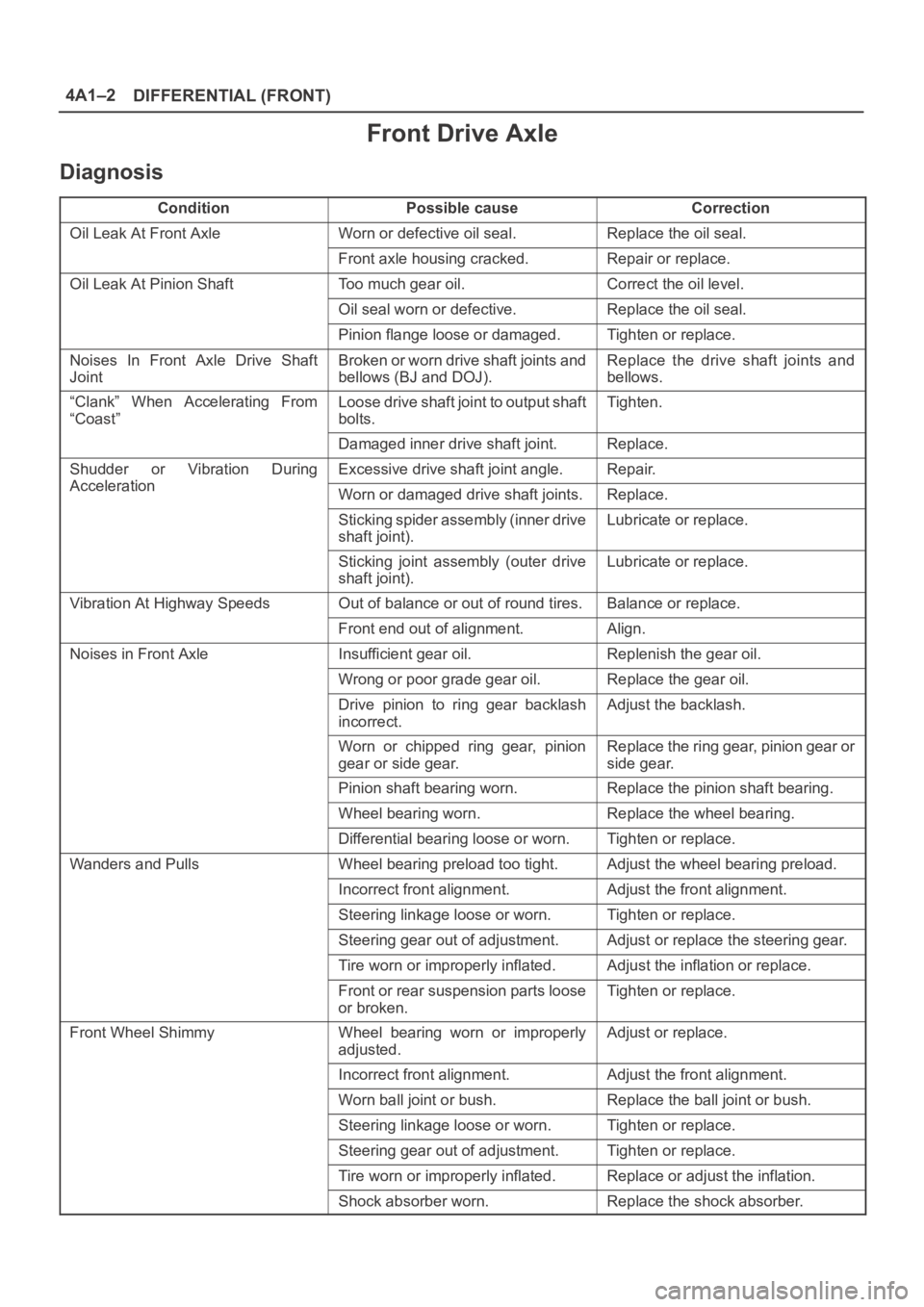
ConditionPossible causeCorrection
Oil Leak At Front AxleWorn or defective oil seal.Replace the oil seal.
Front axle housing cracked.Repair or replace.
Oil Leak At Pinion ShaftToo much gear oil.Correct the oil level.
Oil seal worn or defective.Replace the oil seal.
Pinion flange loose or damaged.Tighten or replace.
Noises In Front Axle Drive Shaft
JointBroken or worn drive shaft joints and
bellows (BJ and DOJ).Replace the drive shaft joints and
bellows.
“Clank” When Accelerating From
“Coast”Loose drive shaft joint to output shaft
bolts.Tighten.
Damaged inner drive shaft joint.Replace.
Shudder or Vibration During
Acceleration
Excessive drive shaft joint angle.Repair.
AccelerationWorn or damaged drive shaft joints.Replace.
Sticking spider assembly (inner drive
shaft joint).Lubricate or replace.
Sticking joint assembly (outer drive
shaft joint).Lubricate or replace.
Vibration At Highway SpeedsOut of balance or out of round tires.Balance or replace.
Front end out of alignment.Align.
Noises in Front AxleInsufficient gear oil.Replenish the gear oil.
Wrong or poor grade gear oil.Replace the gear oil.
Drive pinion to ring gear backlash
incorrect.Adjust the backlash.
Worn or chipped ring gear, pinion
gear or side gear.Replace the ring gear, pinion gear or
side gear.
Pinion shaft bearing worn.Replace the pinion shaft bearing.
Wheel bearing worn.Replace the wheel bearing.
Differential bearing loose or worn.Tighten or replace.
Wanders and PullsWheel bearing preload too tight.Adjust the wheel bearing preload.
Incorrect front alignment.Adjust the front alignment.
Steering linkage loose or worn.Tighten or replace.
Steering gear out of adjustment.Adjust or replace the steering gear.
Tire worn or improperly inflated.Adjust the inflation or replace.
Front or rear suspension parts loose
or broken.Tighten or replace.
Front Wheel ShimmyWheel bearing worn or improperly
adjusted.Adjust or replace.
Incorrect front alignment.Adjust the front alignment.
Worn ball joint or bush.Replace the ball joint or bush.
Steering linkage loose or worn.Tighten or replace.
Steering gear out of adjustment.Tighten or replace.
Tire worn or improperly inflated.Replace or adjust the inflation.
Shock absorber worn.Replace the shock absorber.
Page 669 of 6000

4C–3 DRIVE SHAFT SYSTEM
Diagnosis
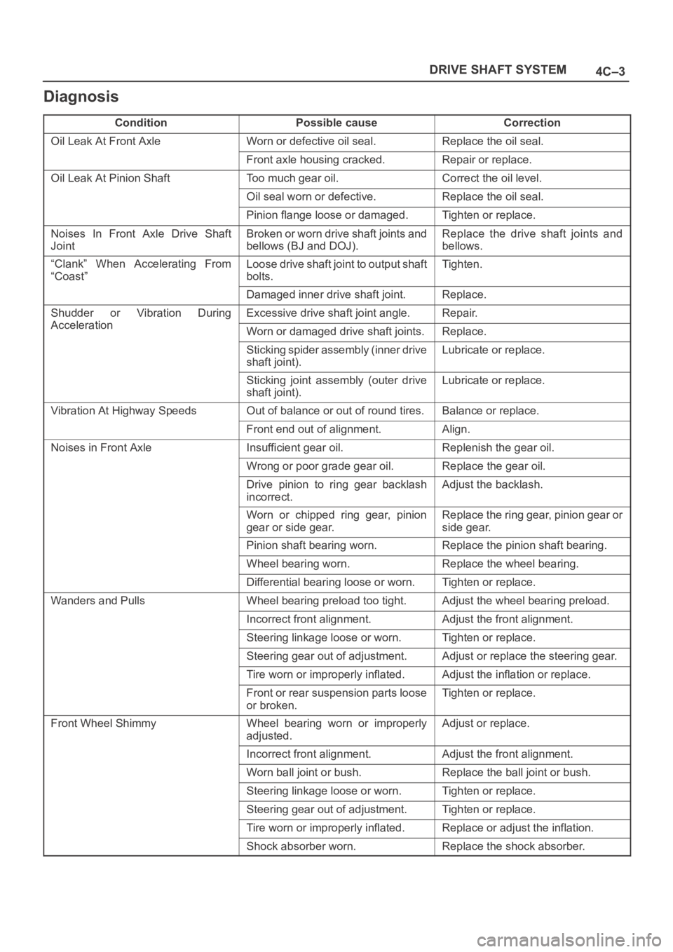
ConditionPossible causeCorrection
Oil Leak At Front AxleWorn or defective oil seal.Replace the oil seal.
Front axle housing cracked.Repair or replace.
Oil Leak At Pinion ShaftToo much gear oil.Correct the oil level.
Oil seal worn or defective.Replace the oil seal.
Pinion flange loose or damaged.Tighten or replace.
Noises In Front Axle Drive Shaft
JointBroken or worn drive shaft joints and
bellows (BJ and DOJ).Replace the drive shaft joints and
bellows.
“Clank” When Accelerating From
“Coast”Loose drive shaft joint to output shaft
bolts.Tighten.
Damaged inner drive shaft joint.Replace.
Shudder or Vibration During
Acceleration
Excessive drive shaft joint angle.Repair.
AccelerationWorn or damaged drive shaft joints.Replace.
Sticking spider assembly (inner drive
shaft joint).Lubricate or replace.
Sticking joint assembly (outer drive
shaft joint).Lubricate or replace.
Vibration At Highway SpeedsOut of balance or out of round tires.Balance or replace.
Front end out of alignment.Align.
Noises in Front AxleInsufficient gear oil.Replenish the gear oil.
Wrong or poor grade gear oil.Replace the gear oil.
Drive pinion to ring gear backlash
incorrect.Adjust the backlash.
Worn or chipped ring gear, pinion
gear or side gear.Replace the ring gear, pinion gear or
side gear.
Pinion shaft bearing worn.Replace the pinion shaft bearing.
Wheel bearing worn.Replace the wheel bearing.
Differential bearing loose or worn.Tighten or replace.
Wanders and PullsWheel bearing preload too tight.Adjust the wheel bearing preload.
Incorrect front alignment.Adjust the front alignment.
Steering linkage loose or worn.Tighten or replace.
Steering gear out of adjustment.Adjust or replace the steering gear.
Tire worn or improperly inflated.Adjust the inflation or replace.
Front or rear suspension parts loose
or broken.Tighten or replace.
Front Wheel ShimmyWheel bearing worn or improperly
adjusted.Adjust or replace.
Incorrect front alignment.Adjust the front alignment.
Worn ball joint or bush.Replace the ball joint or bush.
Steering linkage loose or worn.Tighten or replace.
Steering gear out of adjustment.Tighten or replace.
Tire worn or improperly inflated.Replace or adjust the inflation.
Shock absorber worn.Replace the shock absorber.
Page 703 of 6000

4C–37 DRIVE SHAFT SYSTEM
Front Propeller Shaft
General Description
Since the propeller shaft is balanced carefully, welding or
any other modifications are not permitted.Alignment marks should be applied to each propeller
shaft before removal.
401RW002
Page 714 of 6000

4C–48
DRIVE SHAFT SYSTEM
Rear Propeller Shaft
General Description
Since the propeller shaft is balanced carefully, welding or
any other modifications are not permitted.Alignment marks should be applied to each propeller
shaft before removal.
401RW003
Rear Propeller Shaft and Associated Parts
401RW059
Legend
(1) Bolt, Nut and Washer(2) Rear Propeller Shaft
(3) Bolt, Nut and Washer
Page 759 of 6000

4D1–38
TRANSFER CASE (STANDARD TYPE)
3. Install the sub–gear (23) to the counter gear (22).
4. Install the belleville spring (24).
5. Install the spacer (25) and put the snap ring (29) on
the sub–gear (23).
6. Install the ball bearing (26), using a bench press.
7. Select a snap ring that will allow the minimum axial
play.
Clearance : 0–0.1 mm (0–0.004 in)
Snap ring availability:
ThicknessColor–coding
1.50 mm (0.059 in)White
1.55 mm (0.061 in)Yellow
1.60 mm (0.063 in)Blue
8. Use a pair of snap ring pliers to install the snap ring
(27) to the counter gear (22).
226RS170
226RS021
Sub–Gear (anti–lash plate) Preload
1. Hook a length of piano wire (4) over one of the
sub–gear (5) teeth.
2. Attach the other end of the piano wire (4) to a
spring balancer.
3. Measure the sub–gear preload.
Preload : 59–98 N (6.0–10kg/13–22 lb)
226RS075
9. Install ball bearing (21), using a bench press.
10. Install snap ring (20).
11. Install the counter gear assembly (28) to the transfer
case (1).
12. Use a pair of snap ring pliers to install the snap ring
(29) to the transfer case (1).
NOTE: The snap ring must be fully inserted into the
transfer case snap ring groove.
13. Use a bench press to install the ball bearing (4) to the
front output shaft (5).
262RS012
Page 762 of 6000

TRANSFER CASE (STANDARD TYPE)
4D1–41
27. Use a pair of snap ring pliers to install the snap ring
(19) to the output shaft (5).
Sub gear (anti lash plate) preload (M/T)
1. Hook a length of piano wire (4) over one of the
sub–gear (5) teeth.
2. Attach the other end of the piano wire to (4) a
spring balancer.
3. Measure the sub–gear preload.
Preload: 59–98 N (6.0–10.0kg/13–22 lb)
(M/T)
226RS075
28. Install front output gear assembly (3) to the transfer
case (1).
29. Use a pair of snap ring pliers to install the snap ring (2)
to the transfer case (1).
NOTE: The snap ring must be fully inserted into the
transfer case snap ring groove.
30. Use a bench press to install the ball bearing (32) to the
input shaft (31).
265RS003
31. Install the plate (34), ball (35), and bearing collar (36)
and place the snap ring (33).
32. Install the needle bearing (37) and input gear (38).
33. The clutch hub face (with the heavy boss) must be
facing the transfer input gear side (7).
226RW136
34. Install the high–low clutch hub and sleeve (39), using
a bench press.
35. Install the input shaft assembly (30) to the transfer
case (1).
36. Install the snap ring (33) to the transfer case (1).
NOTE: The snap ring must be fully inserted into the
transfer case snap ring groove.
37. Install the front companion flange temporarily and use
the flange holder 5–8840–0133–0 (J–8614–11) and
lock nut wrench 5–8840–2156–0 (J–37219) to install
the lock nut (40).
Torque: 137 Nꞏm (14.0kgꞏm/101 lb ft)
226RW190
38. Use the punch to stake the lock nut (40) at one spot.
Page 1028 of 6000

6A–72
ENGINE MECHANICAL
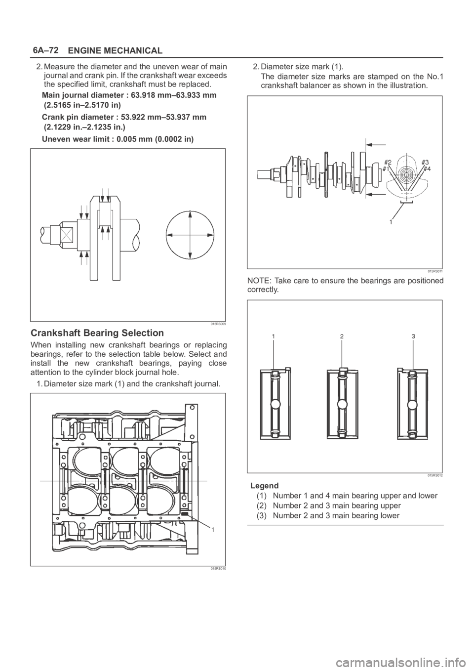
2. Measure the diameter and the uneven wear of main
journal and crank pin. If the crankshaft wear exceeds
the specified limit, crankshaft must be replaced.
Main journal diameter : 63.918 mm–63.933 mm
(2.5165 in–2.5170 in)
Crank pin diameter : 53.922 mm–53.937 mm
(2.1229 in.–2.1235 in.)
Uneven wear limit : 0.005 mm (0.0002 in)
015RS009
Crankshaft Bearing Selection
When installing new crankshaft bearings or replacing
bearings, refer to the selection table below. Select and
install the new crankshaft bearings, paying close
attention to the cylinder block journal hole.
1. Diameter size mark (1) and the crankshaft journal.
015RS010
2. Diameter size mark (1).
The diameter size marks are stamped on the No.1
crankshaft balancer as shown in the illustration.
015RS011
NOTE: Take care to ensure the bearings are positioned
correctly.
015RS012
Legend
(1) Number 1 and 4 main bearing upper and lower
(2) Number 2 and 3 main bearing upper
(3) Number 2 and 3 main bearing lower