1998 OPEL FRONTERA bulb
[x] Cancel search: bulbPage 2567 of 6000
8A–28LIGHTING SYSTEM
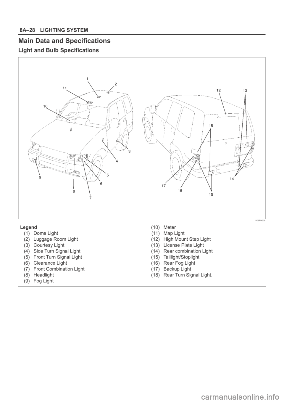
Main Data and Specifications
Light and Bulb Specifications
D08RW539
Legend
(1) Dome Light
(2) Luggage Room Light
(3) Courtesy Light
(4) Side Turn Signal Light
(5) Front Turn Signal Light
(6) Clearance Light
(7) Front Combination Light
(8) Headlight
(9) Fog Light(10) Meter
(11) Map Light
(12) High Mount Step Light
(13) License Plate Light
(14) Rear combination Light
(15) Taillight/Stoplight
(16) Rear Fog Light
(17) Backup Light
(18) Rear Turn Signal Light.
Page 2568 of 6000
LIGHTING SYSTEM8A–29
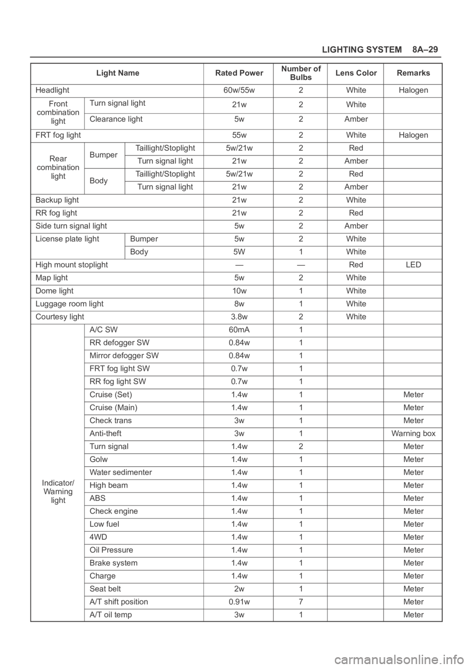
Light NameRated PowerNumber of
BulbsLens ColorRemarks
Headlight60w/55w2WhiteHalogen
FrontTurn signal light21w2Whitecombination
lightClearance light5w2Amber
FRT fog light55w2WhiteHalogen
Taillight/Stoplight5w/21w2Red
RearBumperTurn signal light21w2Ambercombination
lightTaillight/Stoplight5w/21w2RedBodyTurn signal light21w2Amber
Backup light21w2White
RR fog light21w2Red
Side turn signal light5w2Amber
License plate lightBumper5w2White
Body5W1White
High mount stoplight——RedLED
Map light5w2White
Dome light10w1White
Luggage room light8w1White
Courtesy light3.8w2White
A/C SW60mA1
RR defogger SW0.84w1
Mirror defogger SW0.84w1
FRT fog light SW0.7w1
RR fog light SW0.7w1
Cruise (Set)1.4w1Meter
Cruise (Main)1.4w1Meter
Check trans3w1Meter
Anti-theft3w1Warning box
Turn signal1.4w2Meter
Golw1.4w1Meter
Water sedimenter1.4w1Meter
Indicator/High beam1.4w1MeterWa rnin g
lightABS1.4w1Meter
Check engine1.4w1Meter
Low fuel1.4w1Meter
4WD1.4w1Meter
Oil Pressure1.4w1Meter
Brake system1.4w1Meter
Charge1.4w1Meter
Seat belt2w1Meter
A/T shift position0.91w7Meter
A/T oil temp3w1Meter
Page 2992 of 6000
WIRING SYSTEM 8D–399
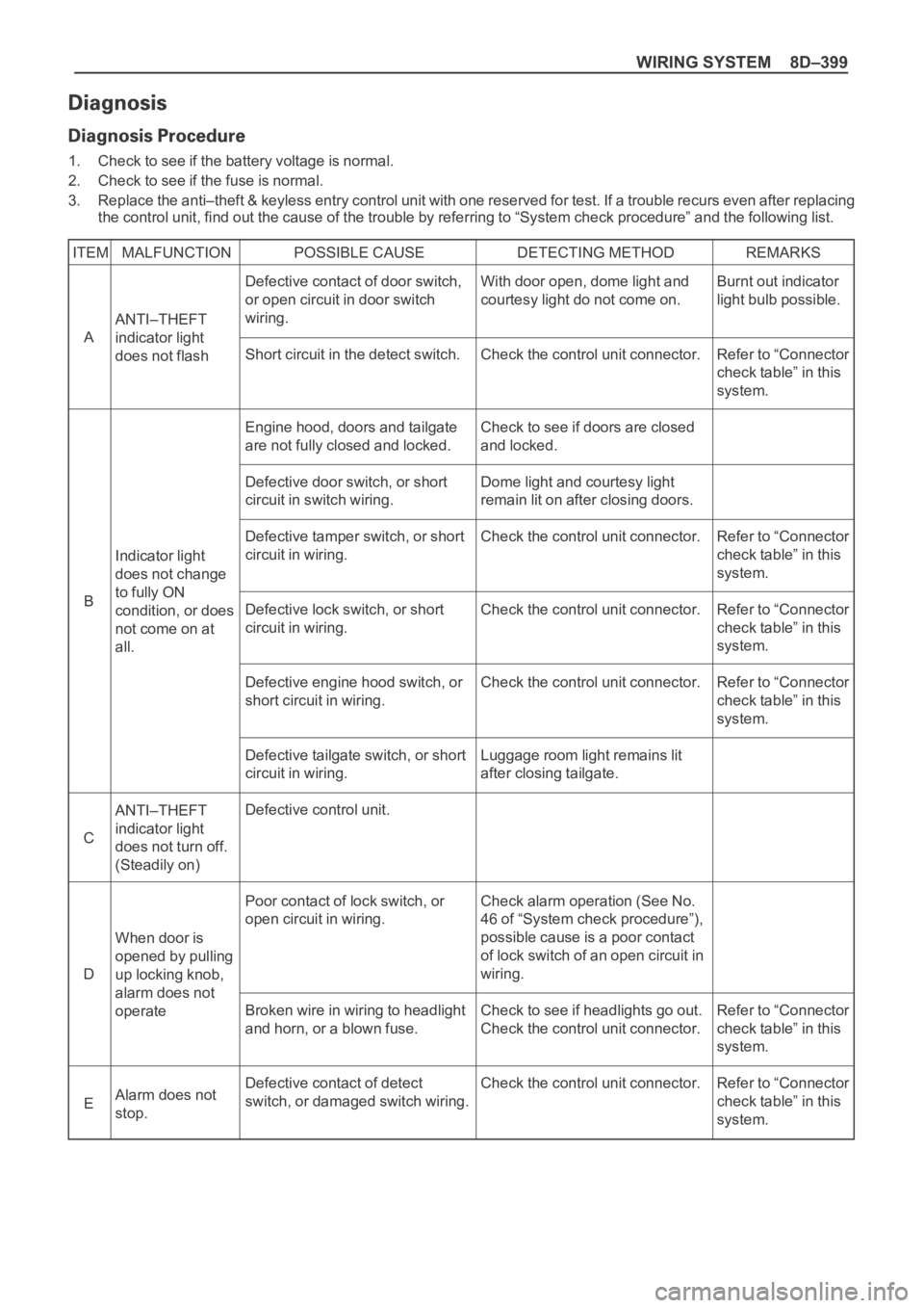
1. Check to see if the battery voltage is normal.
2. Check to see if the fuse is normal.
3. Replace the anti–theft & keyless entry control unit with one reserved for test. If a trouble recurs even after replacing
the control unit, find out the cause of the trouble by referring to “System check procedure” and the following list.
ITEM MALFUNCTION POSSIBLE CAUSE DETECTING METHOD REMARKS
ANTI–THEFT
indicator light
does not flash
ANTI–THEFT
indicator light
does not turn off.
(Steadily on)
When door is
opened by pulling
up locking knob,
alarm does not
operate
Alarm does not
stop. Indicator light
does not change
to fully ON
condition, or does
not come on at
all.Burnt out indicator
light bulb possible.
Refer to “Connector
check table” in this
system.
Refer to “Connector
check table” in this
system.
Refer to “Connector
check table” in this
system.
Refer to “Connector
check table” in this
system.
Refer to “Connector
check table” in this
system.
Refer to “Connector
check table” in this
system. Defective contact of door switch,
or open circuit in door switch
wiring.
Short circuit in the detect switch.
Engine hood, doors and tailgate
are not fully closed and locked.
Defective door switch, or short
circuit in switch wiring.
Defective tamper switch, or short
circuit in wiring.
Defective lock switch, or short
circuit in wiring.
Defective engine hood switch, or
short circuit in wiring.
Defective tailgate switch, or short
circuit in wiring.
Defective control unit.
Poor contact of lock switch, or
open circuit in wiring.
Broken wire in wiring to headlight
and horn, or a blown fuse.
Defective contact of detect
switch, or damaged switch wiring.With door open, dome light and
courtesy light do not come on.
Check the control unit connector.
Check to see if doors are closed
and locked.
Dome light and courtesy light
remain lit on after closing doors.
Check the control unit connector.
Check the control unit connector.
Check the control unit connector.
Luggage room light remains lit
after closing tailgate.
Check alarm operation (See No.
46 of “System check procedure”),
possible cause is a poor contact
of lock switch of an open circuit in
wiring.
Check to see if headlights go out.
Check the control unit connector.
Check the control unit connector. A
C
D
E B
Page 3178 of 6000
METER AND GAUGE8E–1
METER AND GAUGE
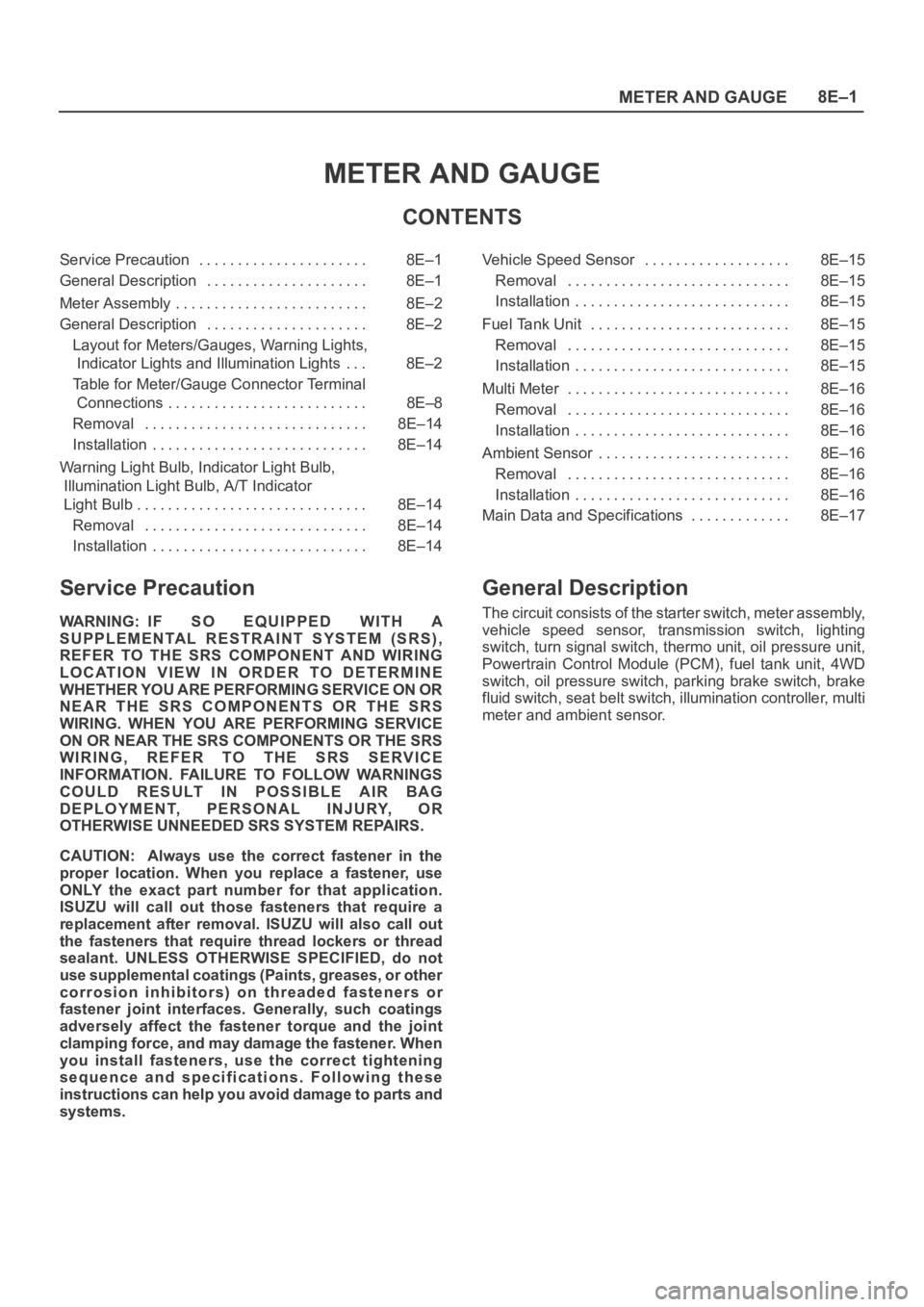
CONTENTS
Service Precaution 8E–1. . . . . . . . . . . . . . . . . . . . . .
General Description 8E–1. . . . . . . . . . . . . . . . . . . . .
Meter Assembly 8E–2. . . . . . . . . . . . . . . . . . . . . . . . .
General Description 8E–2. . . . . . . . . . . . . . . . . . . . .
Layout for Meters/Gauges, Warning Lights,
Indicator Lights and Illumination Lights 8E–2. . .
Table for Meter/Gauge Connector Terminal
Connections 8E–8. . . . . . . . . . . . . . . . . . . . . . . . . .
Removal 8E–14. . . . . . . . . . . . . . . . . . . . . . . . . . . . .
Installation 8E–14. . . . . . . . . . . . . . . . . . . . . . . . . . . .
Warning Light Bulb, Indicator Light Bulb,
Illumination Light Bulb, A/T Indicator
Light Bulb 8E–14. . . . . . . . . . . . . . . . . . . . . . . . . . . . . .
Removal 8E–14. . . . . . . . . . . . . . . . . . . . . . . . . . . . .
Installation 8E–14. . . . . . . . . . . . . . . . . . . . . . . . . . . . Vehicle Speed Sensor 8E–15. . . . . . . . . . . . . . . . . . .
Removal 8E–15. . . . . . . . . . . . . . . . . . . . . . . . . . . . .
Installation 8E–15. . . . . . . . . . . . . . . . . . . . . . . . . . . .
Fuel Tank Unit 8E–15. . . . . . . . . . . . . . . . . . . . . . . . . .
Removal 8E–15. . . . . . . . . . . . . . . . . . . . . . . . . . . . .
Installation 8E–15. . . . . . . . . . . . . . . . . . . . . . . . . . . .
Multi Meter 8E–16. . . . . . . . . . . . . . . . . . . . . . . . . . . . .
Removal 8E–16. . . . . . . . . . . . . . . . . . . . . . . . . . . . .
Installation 8E–16. . . . . . . . . . . . . . . . . . . . . . . . . . . .
Ambient Sensor 8E–16. . . . . . . . . . . . . . . . . . . . . . . . .
Removal 8E–16. . . . . . . . . . . . . . . . . . . . . . . . . . . . .
Installation 8E–16. . . . . . . . . . . . . . . . . . . . . . . . . . . .
Main Data and Specifications 8E–17. . . . . . . . . . . . .
Service Precaution
WARNING: IF SO EQUIPPED WITH A
SUPPLEMENTAL RESTRAINT SYSTEM (SRS),
REFER TO THE SRS COMPONENT AND WIRING
LOCATION VIEW IN ORDER TO DETERMINE
WHETHER YOU ARE PERFORMING SERVICE ON OR
NEAR THE SRS COMPONENTS OR THE SRS
WIRING. WHEN YOU ARE PERFORMING SERVICE
ON OR NEAR THE SRS COMPONENTS OR THE SRS
WIRING, REFER TO THE SRS SERVICE
INFORMATION. FAILURE TO FOLLOW WARNINGS
COULD RESULT IN POSSIBLE AIR BAG
DEPLOYMENT, PERSONAL INJURY, OR
OTHERWISE UNNEEDED SRS SYSTEM REPAIRS.
CAUTION: Always use the correct fastener in the
proper location. When you replace a fastener, use
ONLY the exact part number for that application.
ISUZU will call out those fasteners that require a
replacement after removal. ISUZU will also call out
the fasteners that require thread lockers or thread
sealant. UNLESS OTHERWISE SPECIFIED, do not
use supplemental coatings (Paints, greases, or other
corrosion inhibitors) on threaded fasteners or
fastener joint interfaces. Generally, such coatings
adversely affect the fastener torque and the joint
clamping force, and may damage the fastener. When
you install fasteners, use the correct tightening
sequence and specifications. Following these
instructions can help you avoid damage to parts and
systems.
General Description
The circuit consists of the starter switch, meter assembly,
vehicle speed sensor, transmission switch, lighting
switch, turn signal switch, thermo unit, oil pressure unit,
Powertrain Control Module (PCM), fuel tank unit, 4WD
switch, oil pressure switch, parking brake switch, brake
fluid switch, seat belt switch, illumination controller, multi
meter and ambient sensor.
Page 3191 of 6000
8E–14METER AND GAUGE
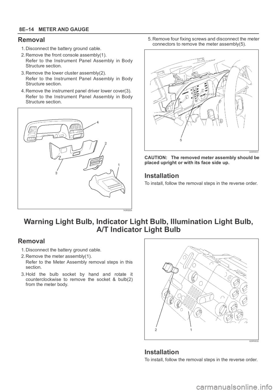
Removal
1. Disconnect the battery ground cable.
2. Remove the front console assembly(1).
Refer to the Instrument Panel Assembly in Body
Structure section.
3. Remove the lower cluster assembly(2).
Refer to the Instrument Panel Assembly in Body
Structure section.
4. Remove the instrument panel driver lower cover(3).
Refer to the Instrument Panel Assembly in Body
Structure section.
740RS004
5. Remove four fixing screws and disconnect the meter
connectors to remove the meter assembly(5).
825RW031
CAUTION: The removed meter assembly should be
placed upright or with its face side up.
Installation
To install, follow the removal steps in the reverse order.
Warning Light Bulb, Indicator Light Bulb, Illumination Light Bulb,
A/T Indicator Light Bulb
Removal
1. Disconnect the battery ground cable.
2. Remove the meter assembly(1).
Refer to the Meter Assembly removal steps in this
section.
3. Hold the bulb socket by hand and rotate it
counterclockwise to remove the socket & bulb(2)
from the meter body.
825RW032
Installation
To install, follow the removal steps in the reverse order.
Page 3444 of 6000
SUPPLEMENTAL RESTRAINT SYSTEM9J–7
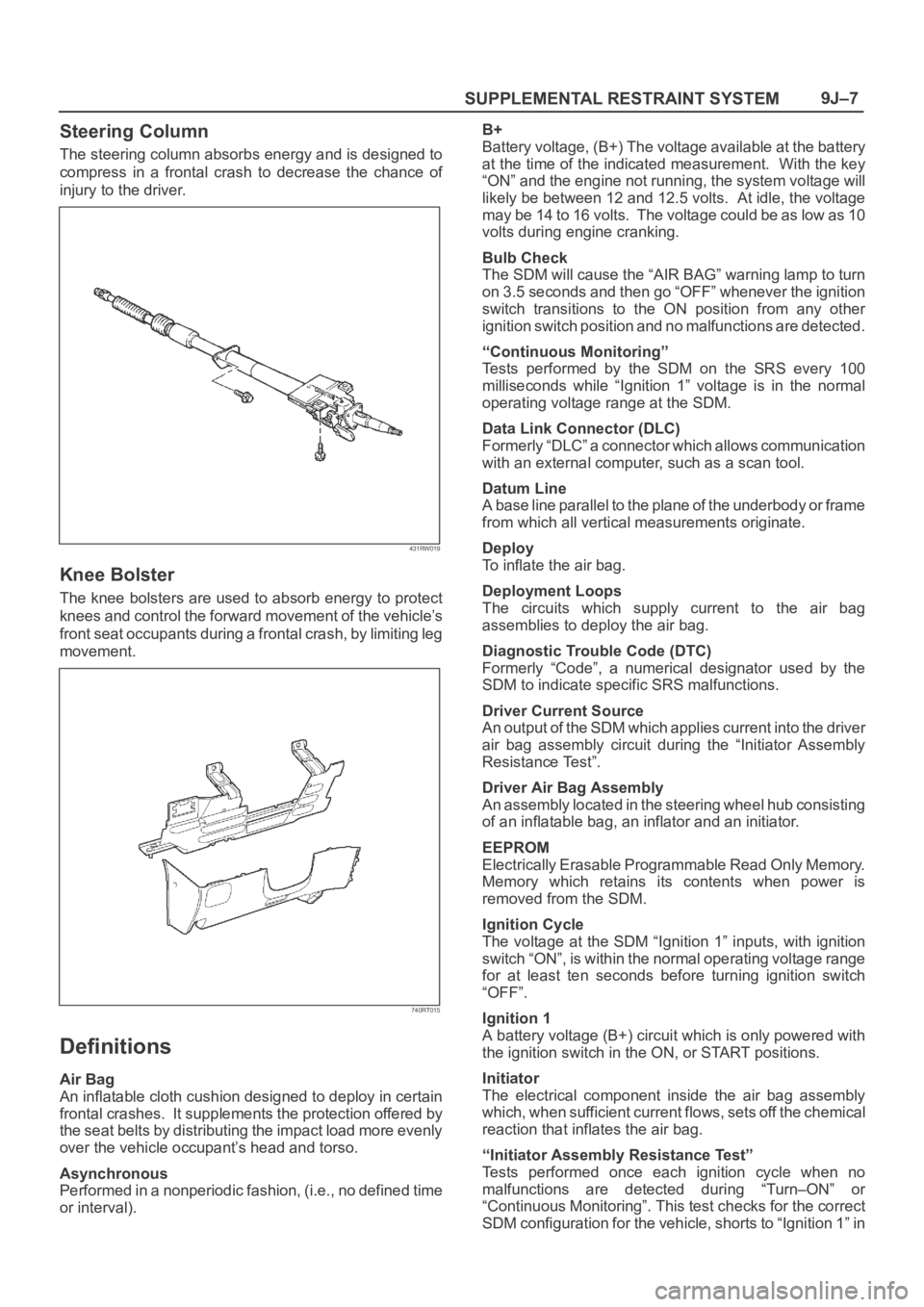
Steering Column
The steering column absorbs energy and is designed to
compress in a frontal crash to decrease the chance of
injury to the driver.
431RW019
Knee Bolster
The knee bolsters are used to absorb energy to protect
knees and control the forward movement of the vehicle’s
front seat occupants during a frontal crash, by limiting leg
movement.
740RT015
Definitions
Air Bag
An inflatable cloth cushion designed to deploy in certain
frontal crashes. It supplements the protection offered by
the seat belts by distributing the impact load more evenly
over the vehicle occupant’s head and torso.
Asynchronous
Performed in a nonperiodic fashion, (i.e., no defined time
or interval).B+
Battery voltage, (B+) The voltage available at the battery
at the time of the indicated measurement. With the key
“ON” and the engine not running, the system voltage will
likely be between 12 and 12.5 volts. At idle, the voltage
may be 14 to 16 volts. The voltage could be as low as 10
volts during engine cranking.
Bulb Check
The SDM will cause the “AIR BAG” warning lamp to turn
on 3.5 seconds and then go “OFF” whenever the ignition
switch transitions to the ON position from any other
ignition switch position and no malfunctions are detected.
“Continuous Monitoring”
Tests performed by the SDM on the SRS every 100
milliseconds while “Ignition 1” voltage is in the normal
operating voltage range at the SDM.
Data Link Connector (DLC)
Formerly “DLC” a connector which allows communication
with an external computer, such as a scan tool.
Datum Line
A base line parallel to the plane of the underbody or frame
from which all vertical measurements originate.
Deploy
To inflate the air bag.
Deployment Loops
The circuits which supply current to the air bag
assemblies to deploy the air bag.
Diagnostic Trouble Code (DTC)
Formerly “Code”, a numerical designator used by the
SDM to indicate specific SRS malfunctions.
Driver Current Source
An output of the SDM which applies current into the driver
air bag assembly circuit during the “Initiator Assembly
Resistance Test”.
Driver Air Bag Assembly
An assembly located in the steering wheel hub consisting
of an inflatable bag, an inflator and an initiator.
EEPROM
Electrically Erasable Programmable Read Only Memory.
Memory which retains its contents when power is
removed from the SDM.
Ignition Cycle
The voltage at the SDM “Ignition 1” inputs, with ignition
switch “ON”, is within the normal operating voltage range
for at least ten seconds before turning ignition switch
“OFF”.
Ignition 1
A battery voltage (B+) circuit which is only powered with
the ignition switch in the ON, or START positions.
Initiator
The electrical component inside the air bag assembly
which, when sufficient current flows, sets off the chemical
reaction that inflates the air bag.
“Initiator Assembly Resistance Test”
Tests performed once each ignition cycle when no
malfunctions are detected during “Turn–ON” or
“Continuous Monitoring”. This test checks for the correct
SDM configuration for the vehicle, shorts to “Ignition 1” in
Page 3498 of 6000
9J1–11
RESTRAINT CONTROL SYSTEM
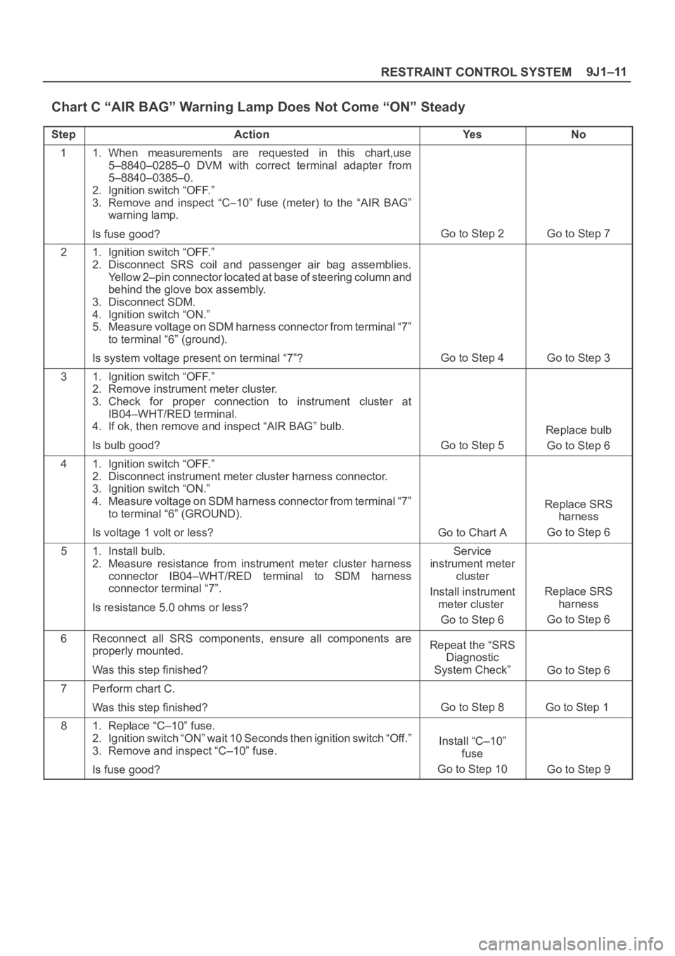
Chart C “AIR BAG” Warning Lamp Does Not Come “ON” Steady
StepActionYe sNo
11. When measurements are requested in this chart,use
5–8840–0285–0 DVM with correct terminal adapter from
5–8840–0385–0.
2. Ignition switch “OFF.”
3. Remove and inspect “C–10” fuse (meter) to the “AIR BAG”
warning lamp.
Is fuse good?
Go to Step 2Go to Step 7
21. Ignition switch “OFF.”
2. Disconnect SRS coil and passenger air bag assemblies.
Yellow 2–pin connector located at base of steering column and
behind the glove box assembly.
3. Disconnect SDM.
4. Ignition switch “ON.”
5. Measure voltage on SDM harness connector from terminal “7”
to terminal “6” (ground).
Is system voltage present on terminal “7”?
Go to Step 4Go to Step 3
31. Ignition switch “OFF.”
2. Remove instrument meter cluster.
3. Check for proper connection to instrument cluster at
IB04–WHT/RED terminal.
4. If ok, then remove and inspect “AIR BAG” bulb.
Is bulb good?
Go to Step 5
Replace bulb
Go to Step 6
41. Ignition switch “OFF.”
2. Disconnect instrument meter cluster harness connector.
3. Ignition switch “ON.”
4. Measure voltage on SDM harness connector from terminal “7”
to terminal “6” (GROUND).
Is voltage 1 volt or less?
Go to Chart A
Replace SRS
harness
Go to Step 6
51. Install bulb.
2. Measure resistance from instrument meter cluster harness
connector IB04–WHT/RED terminal to SDM harness
connector terminal “7”.
Is resistance 5.0 ohms or less?Service
instrument meter
cluster
Install instrument
meter cluster
Go to Step 6
Replace SRS
harness
Go to Step 6
6Reconnect all SRS components, ensure all components are
properly mounted.
Was this step finished?Repeat the “SRS
Diagnostic
System Check”
Go to Step 6
7Perform chart C.
Was this step finished?
Go to Step 8Go to Step 1
81. Replace “C–10” fuse.
2. Ignition switch “ON” wait 10 Seconds then ignition switch “Off.”
3. Remove and inspect “C–10” fuse.
Is fuse good?
Install “C–10”
fuse
Go to Step 10
Go to Step 9
Page 3501 of 6000
RESTRAINT CONTROL SYSTEM 9J1–14
warning lamp is performing the bulb check, unless DTC
17 or DTC 26 is detected. When a scan tool “Clear
Codes” command is issued and the malfunction is stillpresent, the DTC will not reappear until the next ignition
cycle.
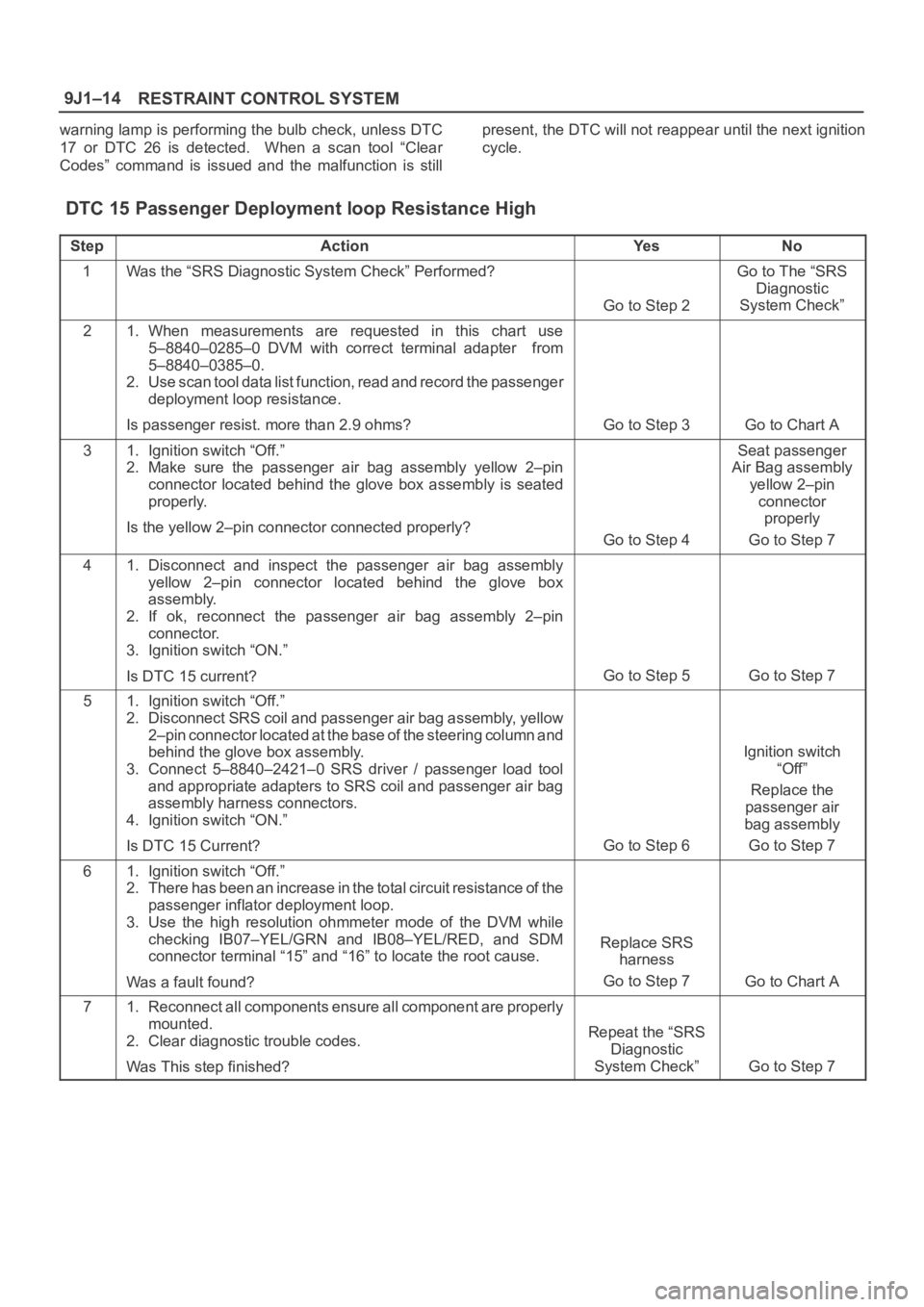
DTC 15 Passenger Deployment loop Resistance High
StepActionYe sNo
1Was the “SRS Diagnostic System Check” Performed?
Go to Step 2
Go to The “SRS
Diagnostic
System Check”
21. When measurements are requested in this chart use
5–8840–0285–0 DVM with correct terminal adapter from
5–8840–0385–0.
2. Use scan tool data list function, read and record the passenger
deployment loop resistance.
Is passenger resist. more than 2.9 ohms?
Go to Step 3Go to Chart A
31. Ignition switch “Off.”
2. Make sure the passenger air bag assembly yellow 2–pin
connector located behind the glove box assembly is seated
properly.
Is the yellow 2–pin connector connected properly?
Go to Step 4
Seat passenger
Air Bag assembly
yellow 2–pin
connector
properly
Go to Step 7
41. Disconnect and inspect the passenger air bag assembly
yellow 2–pin connector located behind the glove box
assembly.
2. If ok, reconnect the passenger air bag assembly 2–pin
connector.
3. Ignition switch “ON.”
Is DTC 15 current?
Go to Step 5Go to Step 7
51. Ignition switch “Off.”
2. Disconnect SRS coil and passenger air bag assembly, yellow
2–pin connector located at the base of the steering column and
behind the glove box assembly.
3. Connect 5–8840–2421–0 SRS driver / passenger load tool
and appropriate adapters to SRS coil and passenger air bag
assembly harness connectors.
4. Ignition switch “ON.”
Is DTC 15 Current?
Go to Step 6
Ignition switch
“Off”
Replace the
passenger air
bag assembly
Go to Step 7
61. Ignition switch “Off.”
2. There has been an increase in the total circuit resistance of t h e
passenger inflator deployment loop.
3. Use the high resolution ohmmeter mode of the DVM while
checking IB07–YEL/GRN and IB08–YEL/RED, and SDM
connector terminal “15” and “16” to locate the root cause.
Was a fault found?
Replace SRS
harness
Go to Step 7
Go to Chart A
71. Reconnect all components ensure all component are properly
mounted.
2. Clear diagnostic trouble codes.
Was This step finished?
Repeat the “SRS
Diagnostic
System Check”
Go to Step 7