1998 OPEL FRONTERA direction
[x] Cancel search: directionPage 274 of 6000

HD6 TYPE COMPRESSOR
Metric Thread Size Information
Compressor to mounting bracket bolts (Front)
M10
1.5 – 6H
Compressor to mounting bracket bolts (Rear)
M8
1.25 – 6H
Suction-discharge port screw
M10
1.5 – 6HCompressor shaft
M9
1.25 – 6H
Internal hub-clutch drive assembly
M22
1.5 – 6H
COMPRESSOR CLUTCH PLATE AND HUB
ASSEMBLY
Removal
1. Clamp the holding fixture J-33026 in a vise and
attach compressor to holding fixture with thumb
screws J-33026-1.
2. With center screw forcing tip in place to thrust
against the end of the shaft, thread the Clutch Plate
and Hub Assembly Installer-Remover J-33013-B into
the hub. Hold the body of the remover with a wrench
and turn the center screw into the remover body to
remove the clutch plate and hub assembly (1).
CAUTION: Do not drive or pound on the clutch hub
or shaft. Internal damage to compressor may
result. The forcing tip on J-33013-B remover-
installer center screw must be flat or the end of the
shaft/axial plate assembly will be damaged.
3. Remove the shaft key and retain for reassembly.
Installation
1. Install the shaft key into the hub key groove. Allow
the key to project approximately 3.2 mm (1/8 in) out
of the keyway. The shaft key is curved slightly to
provide an interference fit in the hub key groove.2. Be sure the frictional surface of the clutch plate and
the clutch rotor (2) are clean before installing the
clutch plate and hub assembly (1).
3. Align the shaft key (4) with the shaft keyway (3) and
place the clutch plate and the hub assembly onto
the compressor shaft.
4. Remove the forcing tip on J-33013-B clutch plate
and hub assembly installer-remover center screw
and reverse the body direction on the center screw,
as shown in Figure.
5. Install the clutch plate and hub installer-remover J-
33013-B with bearing as shown in Figure.
The body of the J-33013-B installer-remover should
be backed off sufficiently to allow the center screw to
be threaded onto the end of the compressor shaft.
6. Hold the center screw with a wrench. Tighten the
hex portion of the installer-remover J-33013-B body
to press the hub onto the shaft. Tighten the body
several turns, remove the installer and check to see
that the shaft key is still in place in the keyway
before installing the clutch plate and hub
assembly to its finial position.The air gap (2)
between frictional surfaces of the clutch plate and
clutch rotor should be 0.50–0.76 mm (.020–.030 in).
1
J-33013-B
J-33026-1
J-33026
901RW001
4
31
2
871RW003
Page 279 of 6000

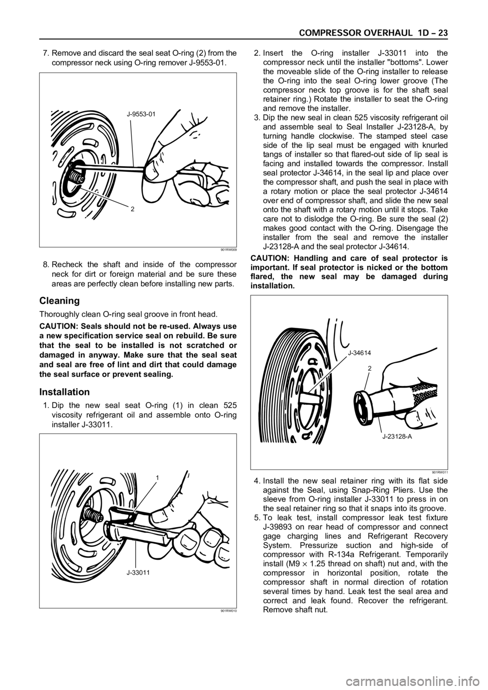
7. Remove and discard the seal seat O-ring (2) from the
compressor neck using O-ring remover J-9553-01.
8. Recheck the shaft and inside of the compressor
neck for dirt or foreign material and be sure these
areas are perfectly clean before installing new parts.
Cleaning
Thoroughly clean O-ring seal groove in front head.
CAUTION: Seals should not be re-used. Always use
a new specification service seal on rebuild. Be sure
that the seal to be installed is not scratched or
damaged in anyway. Make sure that the seal seat
and seal are free of lint and dirt that could damage
the seal surface or prevent sealing.
Installation
1. Dip the new seal seat O-ring (1) in clean 525
viscosity refrigerant oil and assemble onto O-ring
installer J-33011.2. Insert the O-ring installer J-33011 into the
compressor neck until the installer "bottoms". Lower
the moveable slide of the O-ring installer to release
the O-ring into the seal O-ring lower groove (The
compressor neck top groove is for the shaft seal
retainer ring.) Rotate the installer to seat the O-ring
and remove the installer.
3. Dip the new seal in clean 525 viscosity refrigerant oil
and assemble seal to Seal Installer J-23128-A, by
turning handle clockwise. The stamped steel case
side of the lip seal must be engaged with knurled
tangs of installer so that flared-out side of lip seal is
facing and installed towards the compressor. Install
seal protector J-34614, in the seal lip and place over
the compressor shaft, and push the seal in place with
a rotary motion or place the seal protector J-34614
over end of compressor shaft, and slide the new seal
onto the shaft with a rotary motion until it stops. Take
care not to dislodge the O-ring. Be sure the seal (2)
makes good contact with the O-ring. Disengage the
installer from the seal and remove the installer
J-23128-A and the seal protector J-34614.
CAUTION: Handling and care of seal protector is
important. If seal protector is nicked or the bottom
flared, the new seal may be damaged during
installation.
4. Install the new seal retainer ring with its flat side
against the Seal, using Snap-Ring Pliers. Use the
sleeve from O-ring installer J-33011 to press in on
the seal retainer ring so that it snaps into its groove.
5. To leak test, install compressor leak test fixture
J-39893 on rear head of compressor and connect
gage charging lines and Refrigerant Recovery
System. Pressurize suction and high-side of
compressor with R-134a Refrigerant. Temporarily
install (M9
1.25 thread on shaft) nut and, with the
compressor in horizontal position, rotate the
compressor shaft in normal direction of rotation
several times by hand. Leak test the seal area and
correct and leak found. Recover the refrigerant.
Remove shaft nut.
2 J-9553-01
901RW009
1
J-33011
901RW010
J-34614
2
J-23128-A
901RW011
Page 460 of 6000

4A1–23 DIFFERENTIAL (FRONT)
Clearance between the side gear and the
differential box:
Standard: 0.03–0.10 mm (0.001–0.004 in)
Limit: 0.15 mm(0.006 in)
425RS046
Legend
(1) Side Gear
(2) Differential Box
Play in splines between the side gear and
the axle shaft:
Standard: 0.08–0.36 mm(0.003 –0.014 in)
Limit:0.5m (0.02 in)
425RS047
Reassembly
1. Install thrust washer.
2. Install side gear.
3. Install the pinion gear by engaging it with the side
gears while turning both pinion gears simultaneously
in the same direction.
425RS048
4. Install cross pin.
1. Be sure to install the cross pin so that it is in
alignment with the lock pin hole in the differential
cage.
425RS049
2. Adjust the backlash between the side gear and
the pinion gear.
Backlash:0.03 – 0.08 mm (0.001– 0.003 in)
Page 490 of 6000

DIFFERENTIAL (REAR 220mm)
4A2A–23
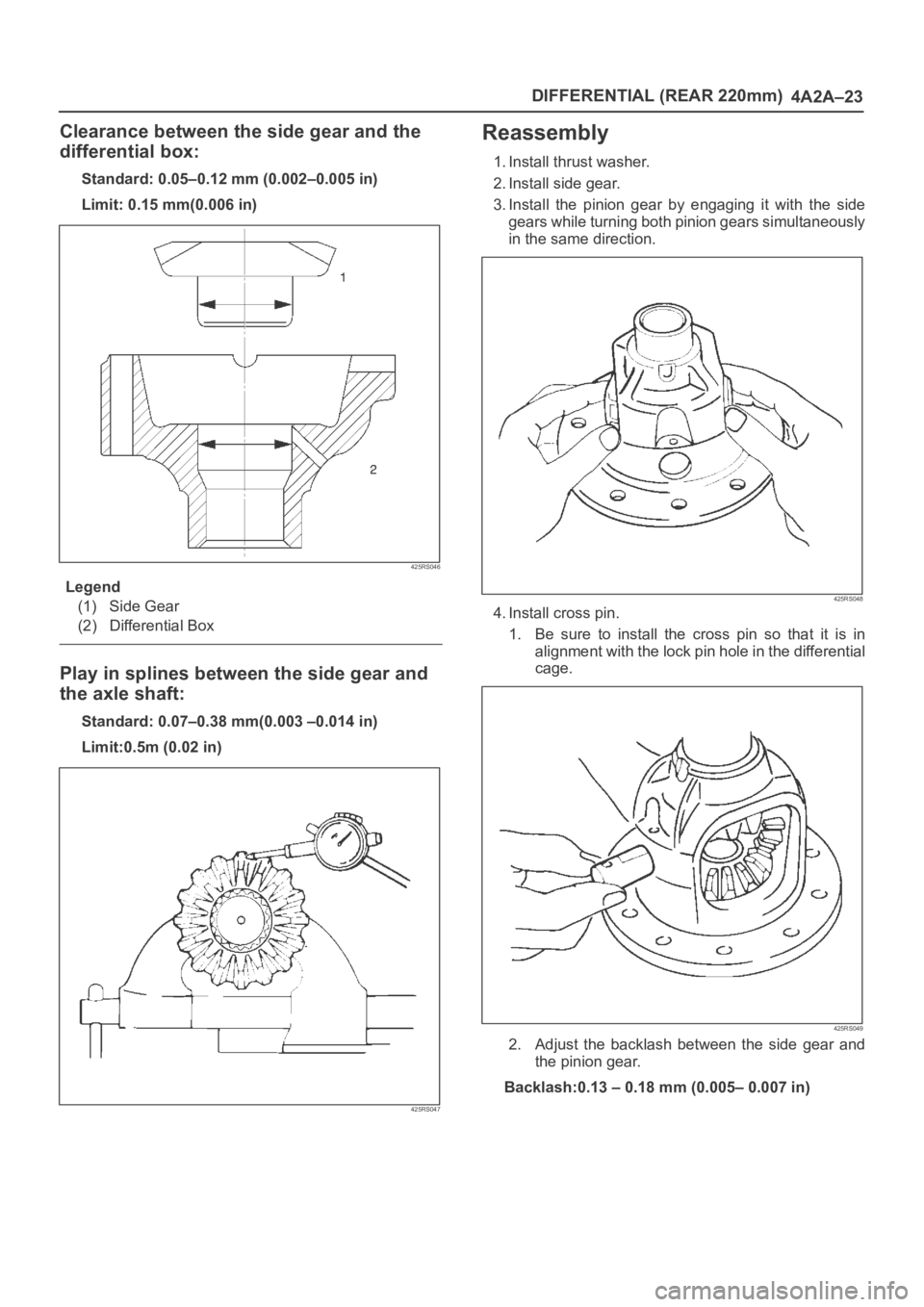
Clearance between the side gear and the
differential box:
Standard: 0.05–0.12 mm (0.002–0.005 in)
Limit: 0.15 mm(0.006 in)
425RS046
Legend
(1) Side Gear
(2) Differential Box
Play in splines between the side gear and
the axle shaft:
Standard: 0.07–0.38 mm(0.003 –0.014 in)
Limit:0.5m (0.02 in)
425RS047
Reassembly
1. Install thrust washer.
2. Install side gear.
3. Install the pinion gear by engaging it with the side
gears while turning both pinion gears simultaneously
in the same direction.
425RS048
4. Install cross pin.
1. Be sure to install the cross pin so that it is in
alignment with the lock pin hole in the differential
cage.
425RS049
2. Adjust the backlash between the side gear and
the pinion gear.
Backlash:0.13 – 0.18 mm (0.005– 0.007 in)
Page 496 of 6000

DIFFERENTIAL (REAR 220mm)
4A2A–29
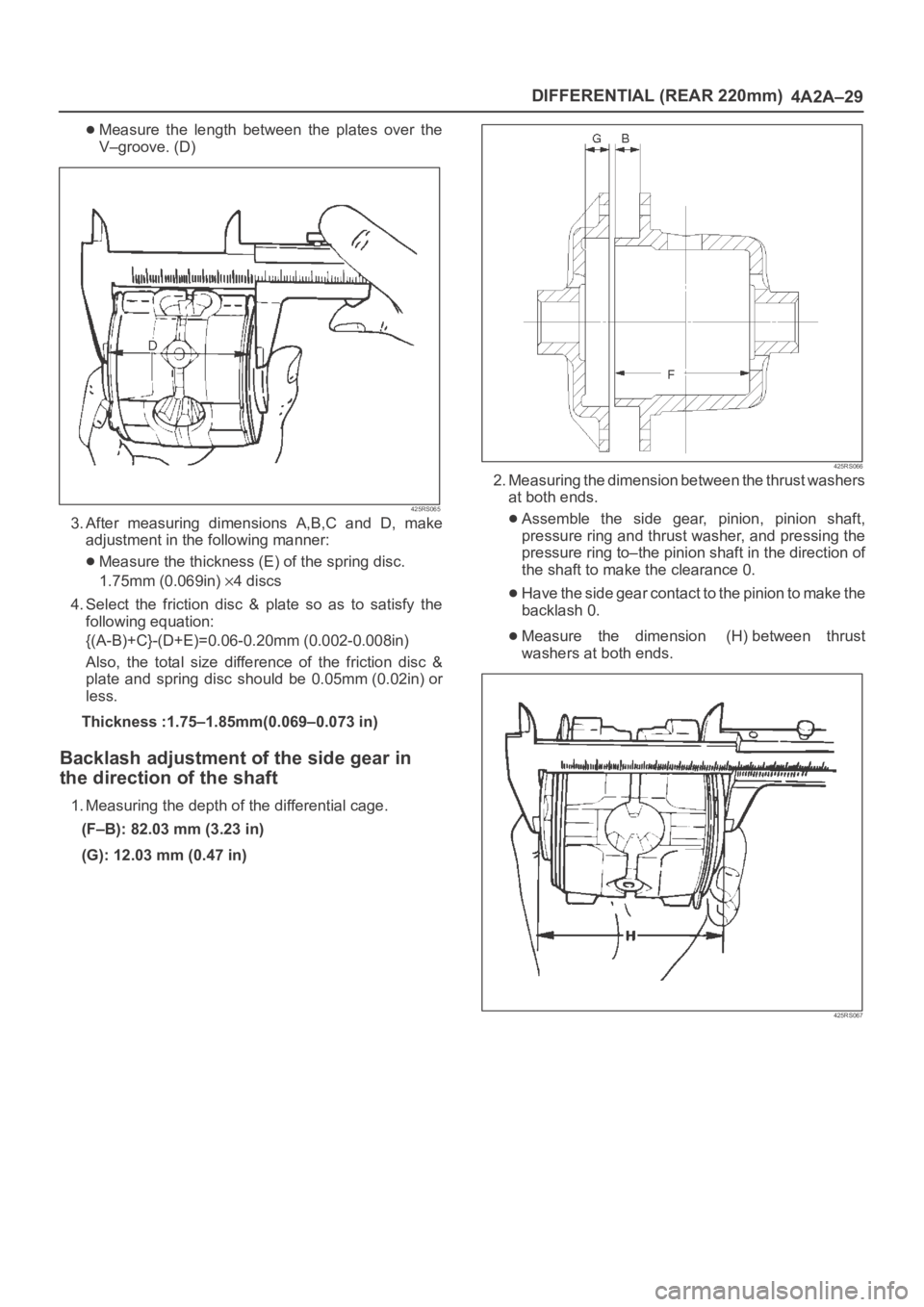
Measure the length between the plates over the
V–groove. (D)
425RS065
3. After measuring dimensions A,B,C and D, make
adjustment in the following manner:
Measure the thickness (E) of the spring disc.
1.75mm (0.069in)
4discs
4. Select the friction disc & plate so as to satisfy the
following equation:
{(A-B)+C}-(D+E)=0.06-0.20mm (0.002-0.008in)
Also, the total size difference of the friction disc &
plate and spring disc should be 0.05mm (0.02in) or
less.
Thickness :1.75–1.85mm(0.069–0.073 in)
Backlash adjustment of the side gear in
the direction of the shaft
1. Measuring the depth of the differential cage.
(F–B): 82.03 mm (3.23 in)
(G): 12.03 mm (0.47 in)
425RS066
2. Measuring the dimension between the thrust washers
at both ends.
Assemble the side gear, pinion, pinion shaft,
pressure ring and thrust washer, and pressing the
pressure ring to–the pinion shaft in the direction of
the shaft to make the clearance 0.
Have the side gear contact to the pinion to make the
backlash 0.
Measure the dimension (H) between thrust
washers at both ends.
425RS067
Page 497 of 6000

4A2A–30
DIFFERENTIAL (REAR 220mm)
3. After measuring dimensions of each of the above
sections, proceed with the adjustment in the following
manner:
Adjust the clearance to satisfy the equation below.
{(F – B) + G – H}=0.05 – 0.20 mm
Also, select the thrust washers so that the
dimensional difference between the back surfaces of
the left and right pressure rings to the thrust washers
is 0.05mm or less.
Thickness : 1.5mm (0.059 in)
1.6 mm(0.063 in)
1.7 mm(0.067 in)
NOTE: When assembling the parts, apply recommended
gear oil sufficiently to each of the parts, especially, to the
contact surfaces and sliding surfaces.
1. Install Differential cage B.
2. Install Thrust washer.
3. Install Spring disc.
When assembling the spring disc, make sure the
mounting direction is correct as shown in figure.
425RS068
Legend
(1) Friction Plate
(2) Spring Disc
(3) Friction Disc
4. Inatall Spring disc.
5. Inatall Friction plate.
6. Inatall Friction disc.
7. Inatall Friction plate.
8. Inatall Friction disc.
9. Inatall Pressure ring.
10. Inatall Side gear.
11. Inatall Pinion and pinion shaft.
12. Inatall Side gear.
13. Inatall Pressure ring.
14. Inatall Friction disc.15. Inatall Friction plate.
16. Inatall Friction disc.
17. Inatall Friction plate.
18. Inatall Spring disc.
When assembling the spring disc, make sure the
mounting direction is correct.
19. Inatall Spring disc.
20. Inatall Thrust washer.
21. Inatall Differential cage A.
22. Inatall Screw.
Matching the guide marks of the differential cages A
and B, tighten the screws evenly in the diagonal
order.
425RS055
Page 525 of 6000

4A2B–22DIFFERENTIAL (REAR 244mm)
2. Install the pinion mate gear with thrust washer by
engaging it with the side gears while turning both
pinion mate gears simultaneously in the same
direction.
425RS048
3. Install differential shaft.
1 . B e s u r e t o i n s t a l l t h e d i f f e r e n t i a l s h a f t s o t h a t i t i s i n
alignment with the lock pin hole in the differential
cage.
425RS049
4. Install lock pin.
After lock pin installation, stake the case to secure the
lock pin.
5. Install ring gear.6. Tighten the bolts in diagonal sequence as illustrated.
Torque: 177Nꞏm (18.0kgꞏm/130 lb ft)
NOTE: Discard used bolts and install new ones.
425RW033
Page 682 of 6000

4C–16
DRIVE SHAFT SYSTEM
Inspection and Repair
Make necessary correction or parts replacement if wear,
damage, corrosion or any other abnormal condition are
found through inspection.
Check the following parts.
Hub
Hub bearing, oil seal
Knuckle spindle
Disc
Caliper
Free wheeling hub parts (Clutch, knob, follower,
inner, ring and spring)
ABS sensor ring (if so equipped)
For inspection and servicing of disc caliper, and relative
parts, refer to Brakes section.
Reassembly
1. Install spacer.
Apply about 1 g wheel bearing grease to both face of
spacer.
2. Install ring.
Apply about 3 g wheel bearing grease to inside face
of ring.
3. Install snap ring
Assembly with grease surplus being left unwiped up
as illustrated.
411RW013
Legend
(1) Inner Assembly
(2) Apply Grease
(3) Body
4. Install inner assembly.
Apply grease to splined portion of body.
5. Install snap ring.6. Install X–ring.
Apply wheel bearing grease to hub lock ring and fit it
in knob paying attention to mounting direction.
NOTE: After fitting, make sure that the hub lock ring is not
twisted.
7. Apply wheel bearing grease to ball and spring and fit
them in knob.
8. Install knob.
1. Apply grease to outer circumference of knob and
inner circumference of cover.
2. Align detent ball (1) to a groove cut in the cover.
411RW014
9. Install snap ring.
Turn the smoother face to knob side.
10. Align the end of retaining spring (1) with clutch spring
groove (2) and fit in the spring.
411RW015