1998 OPEL FRONTERA direction
[x] Cancel search: directionPage 986 of 6000

6A–30
ENGINE MECHANICAL
Installation
NOTE: For correct belt installation, the letter on the belt
must be able to be read as viewed from the front of the
vehicle.
014RY00042
Legend
(1) Crankshaft Timing Pulley
(2) RH Bank Camshaft Drive Gear Pulley
(3) Water Pump Pulley
(4) Idle Pulley
(5) LH Bank Camshaft Drive Gear Pulley
(6) Tension Pulley
014RY00043
Legend
(7) Alignment Mark on Oil Pump.
(8) Alignment Mark on Timing Belt
(9) Alignment Mark (notch) on Crankshaft Timing
Pulley.
(10) Alignment Mark (groove) on Crankshaft Timing
Pulley.
014RW006
Legend
(1) Timing Belt
(2) Engine Rotation Direction
(3) Cylinder Head Side
1. Install timing belt.
1. Align the mark (notch) of crankshaft timing pulley
(2) with mark on oil pump (1).
Align the mark (groove) on the crankshaft timing
pulley (3) with alignment mark (white dots line) on
the timing belt (4).
NOTE: When timing marks are aligned, No.2 piston will
be on Top Dead Center.
014RW003
Legend
(1) Alignment Mark on Oil Pump
(2) Groove on Crankshaft Timing Pulley
(3) Alignment Mark on Crankshaft Timing Pulley
(4) Alignment Mark on Timing Belt
Page 988 of 6000

6A–32
ENGINE MECHANICAL
Legend
(1) Up Side
(2) Down Side
(3) Direction for Installation
(4) Locking Pin
3. Remove double clips or equivalent clips, from
timing belt pulleys.
Turn the crankshaft pulley clockwise by two turns.
3. Install timing belt cover.
Remove crankshaft pulley that was installed in step
1 item 5.
Tighten bolts to the specified torque.
Torque: 19 Nꞏm (1.9 Kgꞏm/14 lb ft)
020RW004
Legend
(1) Timing Belt Cover RH
(2) Timing Belt Cover LH
(3) Timing Belt Cover Lower
020RW003
Legend
(1) Timing Belt Cover
(2) Rubber Bushing
(3) Sealing Rubber
(4) Cylinder Body
4. Install crankshaft pulley using 5–8840–0133–0, hold
the crankshaft pulley and tighten center bolt to the
specified torque.
Torque : 167 Nꞏm (17.0 Kgꞏm/123 lb ft)
5. Install fan pulley bracket and tighten fixing bolts to the
specified torque.
Torque : 22 Nꞏm (2.2 Kgꞏm/16 lb ft)
6. Install power steering pump assembly and tighten to
the specified torque.
To r q u e :
M8 bolt : 22 Nꞏm (2.2 Kgꞏm/16 lb ft)
M10 bolt : 46 Nꞏm (4.7 Kgꞏm/34 lb ft)
7. Install cooling fan assembly and tighten bolts/nuts to
the specified torque.
Torque : 22 Nꞏm (2.2 Kgꞏm/16 lb ft) for fan pulley
and fan bracket.
Torque : 10 Nꞏm (1.0 Kgꞏm/88.5 lb in) for fan and
clutch assembly.
8. Move drive belt tensioner to loose side using wrench,
then install drive belt to normal position.
850RW001
Legend
(1) Crankshaft Pulley
(2) Cooling Fan Pulley
(3) Auto Tensioner
(4) Generator
(5) Air Conditioner Compressor
(6) Power Steering Oil Pump
(7) Idle Pulley
(8) Drive Belt
9. Install radiator upper fan shroud.
10. Install air cleaner assembly.
Page 989 of 6000

6A–33
ENGINE MECHANICAL
Camshaft
Removal
1. Disconnect battery ground cable.
2. Remove crankshaft pulley.
Refer to removal procedure for Crankshaft Pulley in
this manual.
3. Remove timing belt.
Refer to removal procedure for Timing Belt in this
manual.
4. Remove cylinder head cover LH.
Refer to removal procedure for Cylinder Head
Cover LH in this manual.
5. Remove cylinder head cover RH.
Refer to removal procedure for Cylinder Head
Cover RH in this manual.
6. Remove twenty fixing bolts from inlet and exhaust
camshaft bracket on one side bank, then camshaft
brackets.
014RW027
7. Remove camshaft assembly.
8. Remove fixing bolt for camshaft drive gear pulley.
9. Remove three fixing bolts from camshaft drive gear
retainer, then camshaft drive gear assembly.
014RW026
Legend
(1) Right Bank
(2) Left Bank
(3) Timing Mark on Retainer
Installation
1. Install camshaft drive gear assembly and tighten
three bolts to the specified torque.
Torque : 10 Nꞏm (1.0 Kgꞏm/89 lb in)
2. Tighten bolt for camshaft drive gear assembly pulley
to the specified torque.
Torque : 98 Nꞏm (10.0 Kgꞏm/72 lb ft)
3. Tighten sub gear setting bolt.
1. Use the 5–8840–2443–0 gear spring lever to turn
sub gear to right direction until it aligns with the M5
bolt hole between camshaft driven gear and sub
gear.
2. Tighten the M5 bolt to a suitable torque to prevent
the sub gear from moving.
Page 1009 of 6000
6A–53
ENGINE MECHANICAL
2. Remove camshaft bracket fixing bolt (5), camshaft
bracket (6), then camshaft exhaust (7), and intake
side (8).
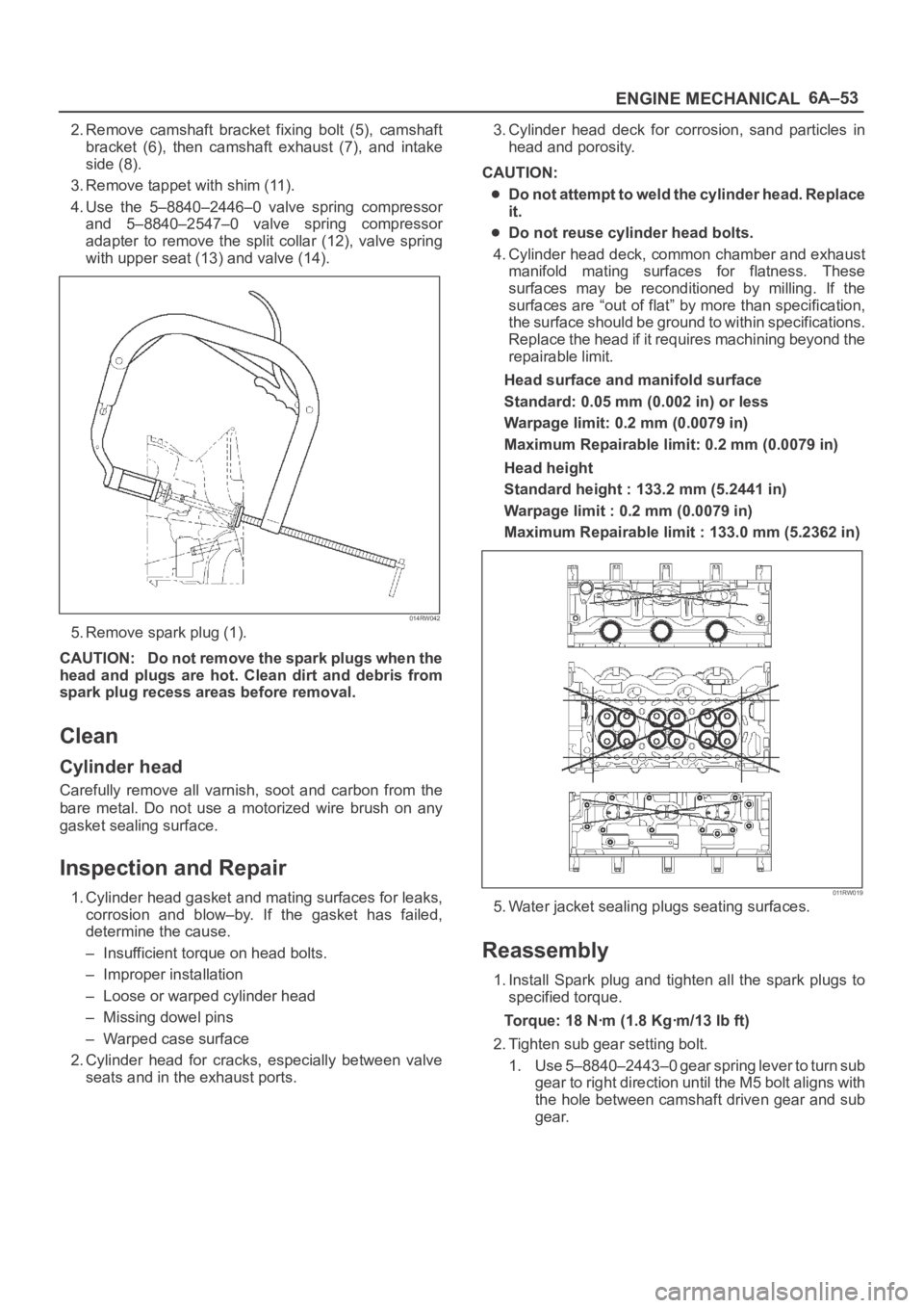
3. Remove tappet with shim (11).
4. Use the 5–8840–2446–0 valve spring compressor
and 5–8840–2547–0 valve spring compressor
adapter to remove the split collar (12), valve spring
with upper seat (13) and valve (14).
014RW042
5. Remove spark plug (1).
CAUTION: Do not remove the spark plugs when the
head and plugs are hot. Clean dirt and debris from
spark plug recess areas before removal.
Clean
Cylinder head
Carefully remove all varnish, soot and carbon from the
bare metal. Do not use a motorized wire brush on any
gasket sealing surface.
Inspection and Repair
1. Cylinder head gasket and mating surfaces for leaks,
corrosion and blow–by. If the gasket has failed,
determine the cause.
– Insufficient torque on head bolts.
– Improper installation
– Loose or warped cylinder head
– Missing dowel pins
– Warped case surface
2. Cylinder head for cracks, especially between valve
seats and in the exhaust ports.3. Cylinder head deck for corrosion, sand particles in
head and porosity.
CAUTION:
Do not attempt to weld the cylinder head. Replace
it.
Do not reuse cylinder head bolts.
4. Cylinder head deck, common chamber and exhaust
manifold mating surfaces for flatness. These
surfaces may be reconditioned by milling. If the
surfaces are “out of flat” by more than specification,
the surface should be ground to within specifications.
Replace the head if it requires machining beyond the
repairable limit.
Head surface and manifold surface
Standard: 0.05 mm (0.002 in) or less
Warpage limit: 0.2 mm (0.0079 in)
Maximum Repairable limit: 0.2 mm (0.0079 in)
Head height
Standard height : 133.2 mm (5.2441 in)
Warpage limit : 0.2 mm (0.0079 in)
Maximum Repairable limit : 133.0 mm (5.2362 in)
011RW019
5. Water jacket sealing plugs seating surfaces.
Reassembly
1. Install Spark plug and tighten all the spark plugs to
specified torque.
Torque: 18 Nꞏm (1.8 Kgꞏm/13 lb ft)
2. Tighten sub gear setting bolt.
1. Use 5–8840–2443–0 gear spring lever to turn sub
gear to right direction until the M5 bolt aligns with
the hole between camshaft driven gear and sub
gear.
Page 1022 of 6000
6A–66
ENGINE MECHANICAL
Limit : 0.12 mm (0.0047 mm)
014RW035
Reassembly
1. Install camshaft drive gear assembly and tighten
three bolts to specified torque.
Torque: 10 Nꞏm (1.0 Kgꞏm/89 lb in)
2. Tighten sub gear setting bolt.
1. Use 5–8840–2443–0 to turn sub gear to right
direction until the M5 bolt hole aligns between
camshaft driven gear and sub gear.
2. Tighten M5 bolt suitable torque for prevent
moving the sub gear.
014RW041
3. Install camshaft assembly and camshaft brackets,
tighten twenty bolts on one side bank to the specified
torque.
1. Apply engine oil to camshaft journal and bearing
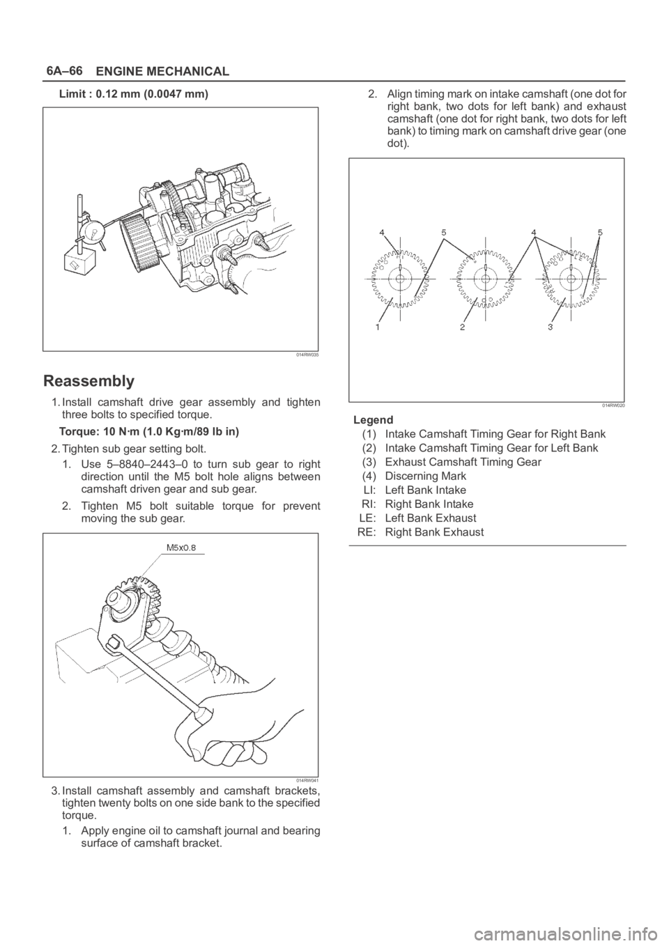
surface of camshaft bracket.2. Align timing mark on intake camshaft (one dot for
right bank, two dots for left bank) and exhaust
camshaft (one dot for right bank, two dots for left
bank) to timing mark on camshaft drive gear (one
dot).
014RW020
Legend
(1) Intake Camshaft Timing Gear for Right Bank
(2) Intake Camshaft Timing Gear for Left Bank
(3) Exhaust Camshaft Timing Gear
(4) Discerning Mark
LI: Left Bank Intake
RI: Right Bank Intake
LE: Left Bank Exhaust
RE: Right Bank Exhaust
Page 1036 of 6000
6A–80
ENGINE MECHANICAL
015RS026
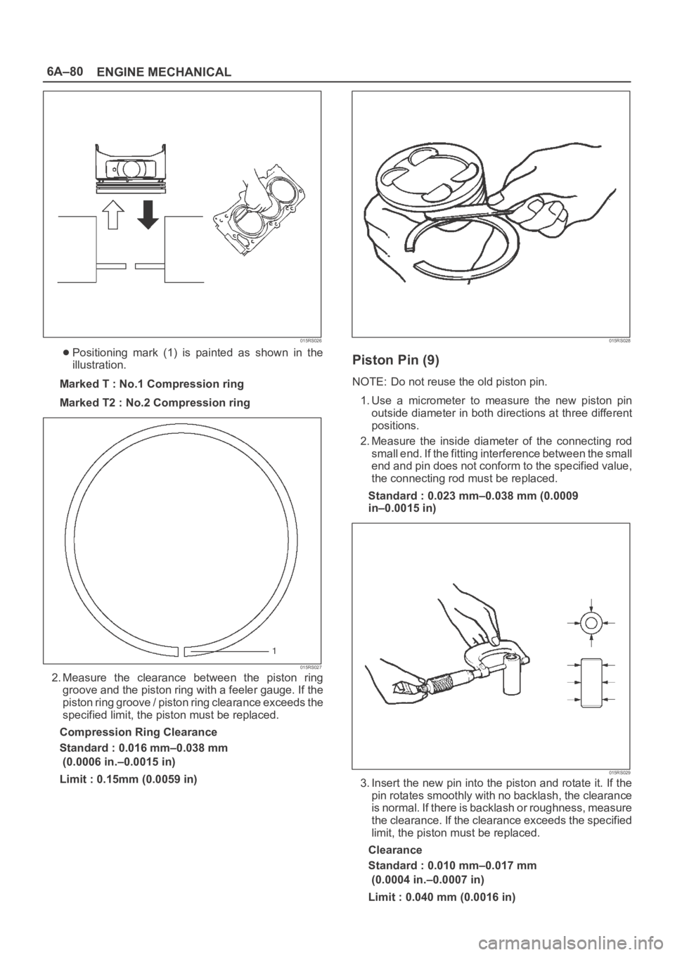
Positioning mark (1) is painted as shown in the
illustration.
Marked T : No.1 Compression ring
Marked T2 : No.2 Compression ring
015RS027
2. Measure the clearance between the piston ring
groove and the piston ring with a feeler gauge. If the
piston ring groove / piston ring clearance exceeds the
specified limit, the piston must be replaced.
Compression Ring Clearance
Standard : 0.016 mm–0.038 mm
(0.0006 in.–0.0015 in)
Limit : 0.15mm (0.0059 in)
015RS028
Piston Pin (9)
NOTE: Do not reuse the old piston pin.
1. Use a micrometer to measure the new piston pin
outside diameter in both directions at three different
positions.
2. Measure the inside diameter of the connecting rod
small end. If the fitting interference between the small
end and pin does not conform to the specified value,
the connecting rod must be replaced.
Standard : 0.023 mm–0.038 mm (0.0009
in–0.0015 in)
015RS029
3. Insert the new pin into the piston and rotate it. If the
pin rotates smoothly with no backlash, the clearance
is normal. If there is backlash or roughness, measure
the clearance. If the clearance exceeds the specified
limit, the piston must be replaced.
Clearance
Standard : 0.010 mm–0.017 mm
(0.0004 in.–0.0007 in)
Limit : 0.040 mm (0.0016 in)
Page 1042 of 6000
6A–86
ENGINE MECHANICAL
11. Remove rear oil seal retainer assembly.
12. Remove main bearing cap.
13. Remove crankshaft.
14. Remove cylinder block.
Inspection and Repair
1. Remove the cylinder head gasket and any other
material adhering to the upper surface of the cylinder
block. Be very careful not to allow any material to
accidentally drop into the cylinder block. Be very
careful not to scratch the cylinder block.
2. Carefully remove the oil pump, rear oil seal retainer,
and crankcase assembly installation surface seal.
3. Wipe the cylinder block clean.
4. Visually inspect the cylinder block. If necessary, use a
flaw detector to perform a dye penetrate and
hydraulic (or air pressure) test. If cracking or other
damage is discovered, the cylinder block must either
be repaired or replaced.
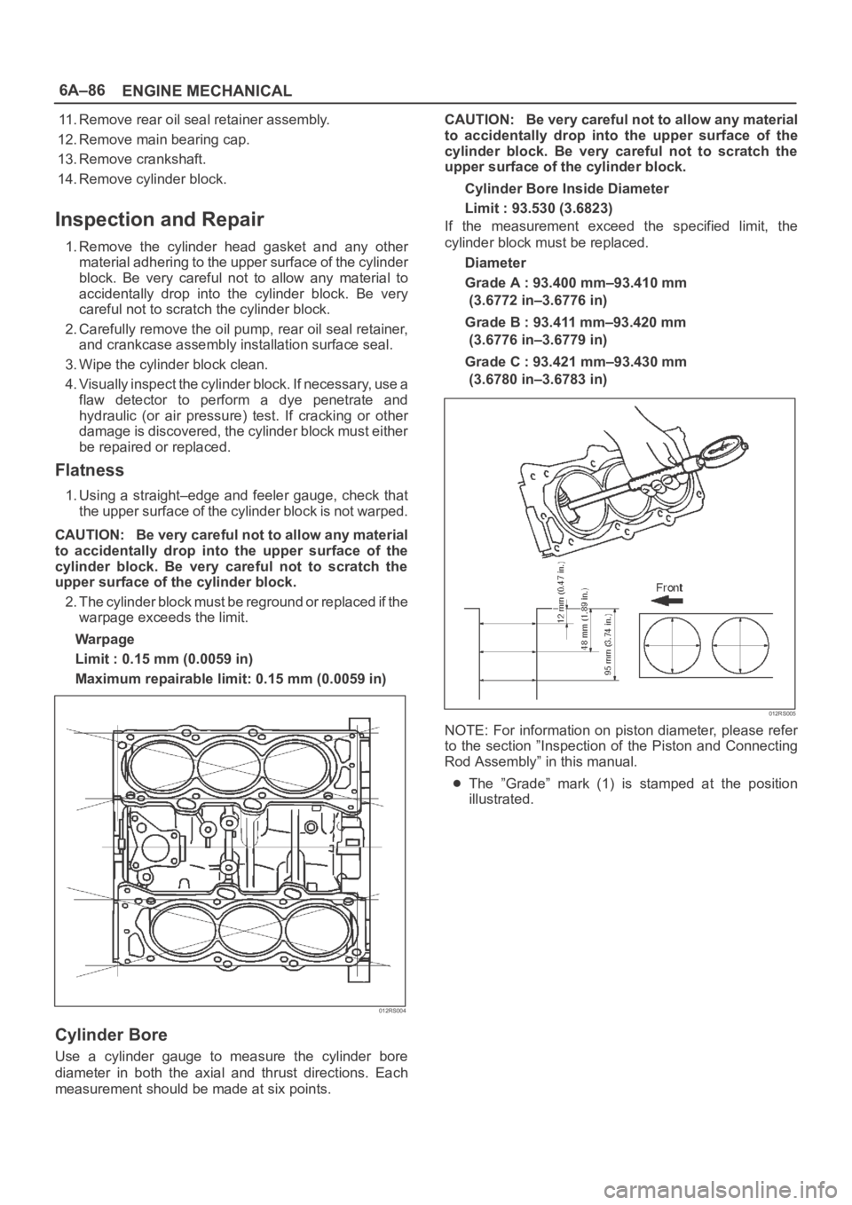
Flatness
1. Using a straight–edge and feeler gauge, check that
the upper surface of the cylinder block is not warped.
CAUTION: Be very careful not to allow any material
to accidentally drop into the upper surface of the
cylinder block. Be very careful not to scratch the
upper surface of the cylinder block.
2. The cylinder block must be reground or replaced if the
warpage exceeds the limit.
Warpage
Limit : 0.15 mm (0.0059 in)
Maximum repairable limit: 0.15 mm (0.0059 in)
012RS004
Cylinder Bore
Use a cylinder gauge to measure the cylinder bore
diameter in both the axial and thrust directions. Each
measurement should be made at six points.CAUTION: Be very careful not to allow any material
to accidentally drop into the upper surface of the
cylinder block. Be very careful not to scratch the
upper surface of the cylinder block.
Cylinder Bore Inside Diameter
Limit : 93.530 (3.6823)
If the measurement exceed the specified limit, the
cylinder block must be replaced.
Diameter
Grade A : 93.400 mm–93.410 mm
(3.6772 in–3.6776 in)
Grade B : 93.411 mm–93.420 mm
(3.6776 in–3.6779 in)
Grade C : 93.421 mm–93.430 mm
(3.6780 in–3.6783 in)
012RS005
NOTE: For information on piston diameter, please refer
to the section ”Inspection of the Piston and Connecting
Rod Assembly” in this manual.
The ”Grade” mark (1) is stamped at the position
illustrated.
Page 1065 of 6000
6B–12
ENGINE COOLING
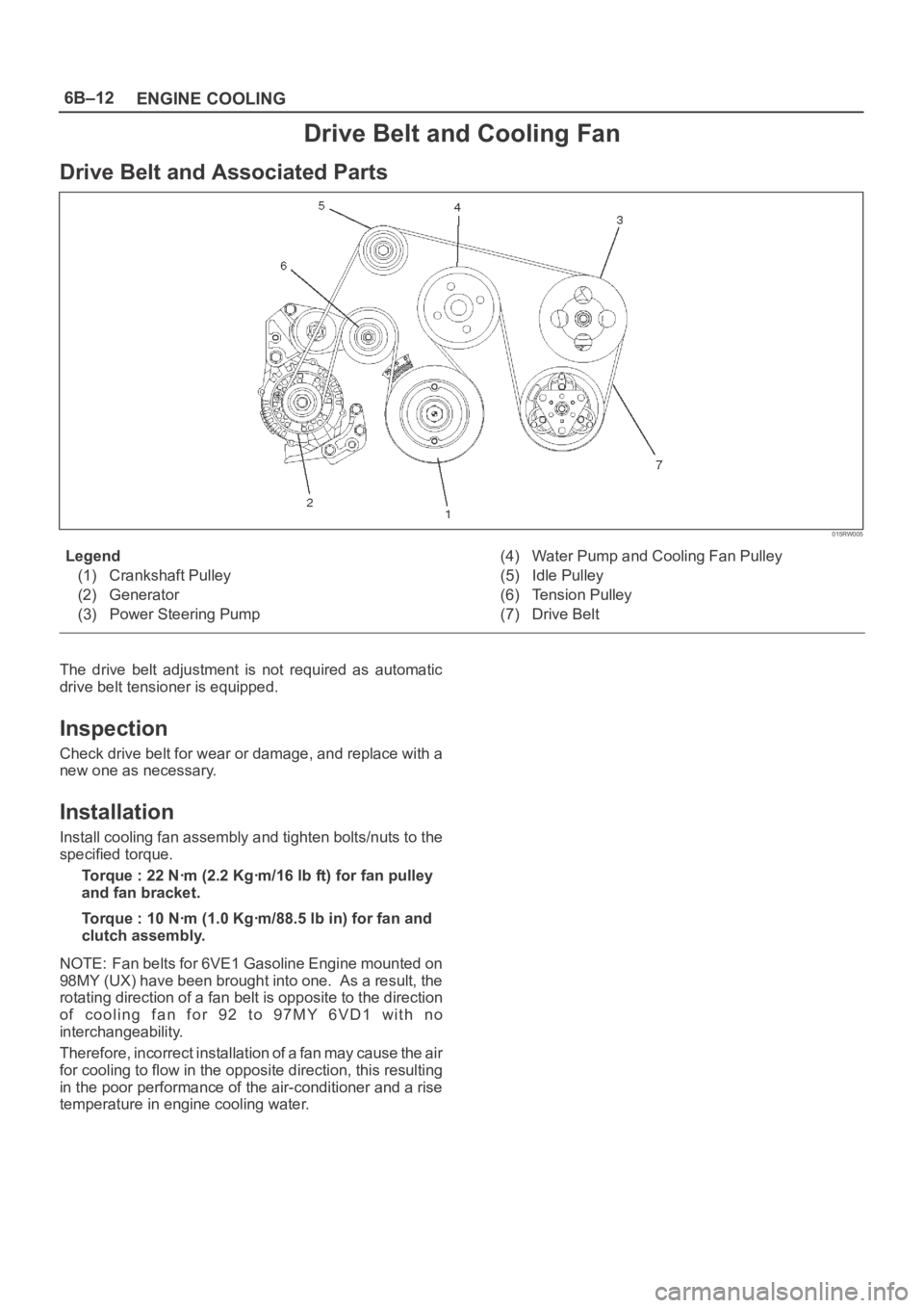
Drive Belt and Cooling Fan
Drive Belt and Associated Parts
015RW005
Legend
(1) Crankshaft Pulley
(2) Generator
(3) Power Steering Pump(4) Water Pump and Cooling Fan Pulley
(5) Idle Pulley
(6) Tension Pulley
(7) Drive Belt
The drive belt adjustment is not required as automatic
drive belt tensioner is equipped.
Inspection
Check drive belt for wear or damage, and replace with a
new one as necessary.
Installation
Install cooling fan assembly and tighten bolts/nuts to the
specified torque.
Torque : 22 Nꞏm (2.2 Kgꞏm/16 lb ft) for fan pulley
and fan bracket.
Torque : 10 Nꞏm (1.0 Kgꞏm/88.5 lb in) for fan and
clutch assembly.
NOTE: Fan belts for 6VE1 Gasoline Engine mounted on
98MY (UX) have been brought into one. As a result, the
rotating direction of a fan belt is opposite to the direction
o f c o o l i n g f a n f o r 9 2 t o 9 7 M Y 6 V D 1 w i t h n o
interchangeability.
Therefore, incorrect installation of a fan may cause the air
for cooling to flow in the opposite direction, this resulting
in the poor performance of the air-conditioner and a rise
temperature in engine cooling water.