1998 OPEL FRONTERA trailer
[x] Cancel search: trailerPage 971 of 6000
6A–15
ENGINE MECHANICAL
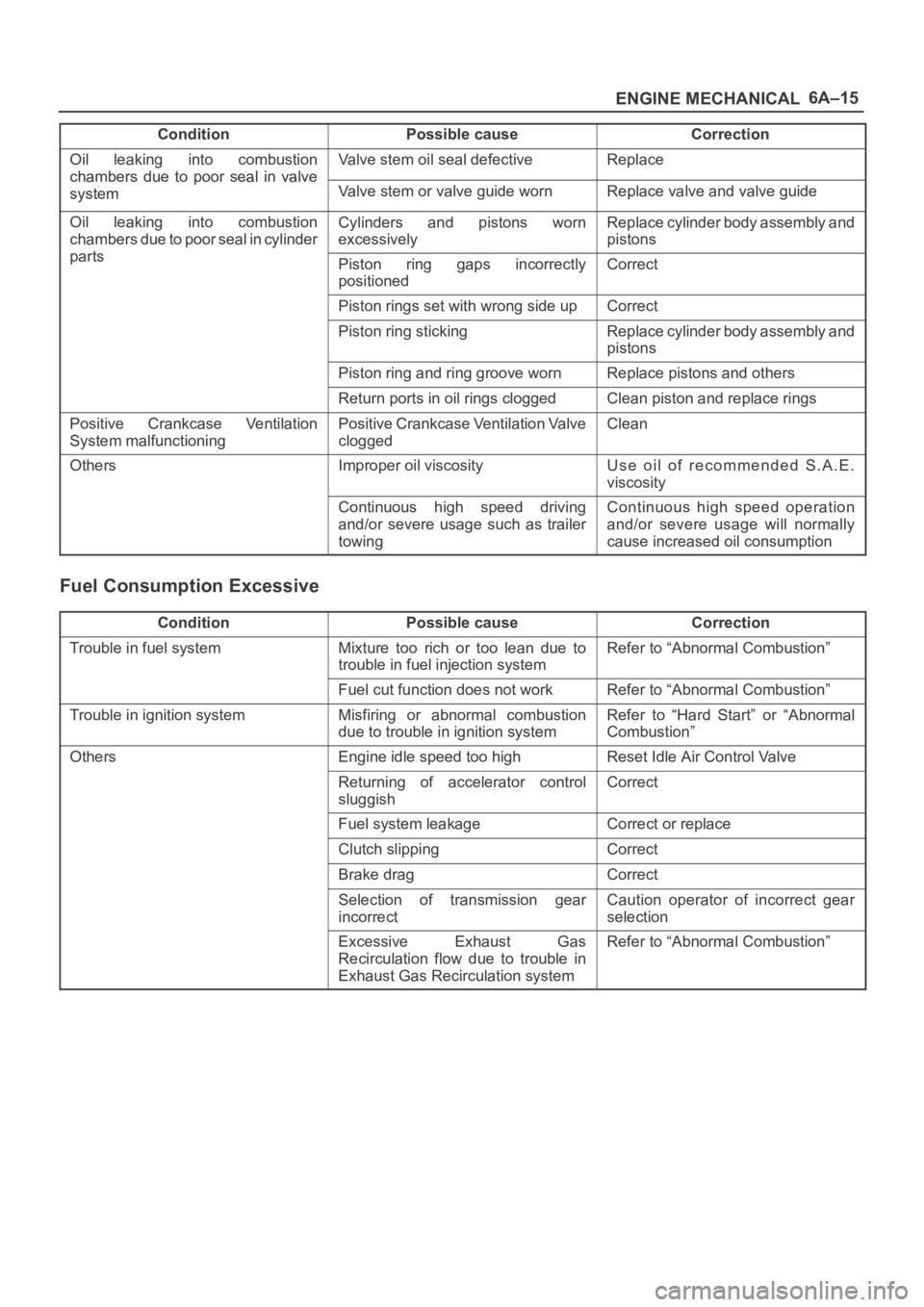
Condition CorrectionPossible cause
Oil leaking into combustion
chambers due topoor seal in valve
Valve stem oil seal defectiveReplace
chambers due to oor seal in valve
systemValve stem or valve guide wornReplace valve and valve guide
Oil leaking into combustion
chambers due to poor seal in cylinder
t
Cylinders and pistons worn
excessivelyReplace cylinder body assembly and
pistons
partsPiston ring gaps incorrectly
positionedCorrect
Piston rings set with wrong side upCorrect
Piston ring stickingReplace cylinder body assembly and
pistons
Piston ring and ring groove wornReplace pistons and others
Return ports in oil rings cloggedClean piston and replace rings
Positive Crankcase Ventilation
System malfunctioningPositive Crankcase Ventilation Valve
cloggedClean
OthersImproper oil viscosityUse oil of recommended S.A.E.
viscosity
Continuous high speed driving
and/or severe usage such as trailer
towingContinuous high speed operation
and/or severe usage will normally
cause increased oil consumption
Fuel Consumption Excessive
ConditionPossible causeCorrection
Trouble in fuel systemMixture too rich or too lean due to
trouble in fuel injection systemRefer to “Abnormal Combustion”
Fuel cut function does not workRefer to “Abnormal Combustion”
Trouble in ignition systemMisfiring or abnormal combustion
due to trouble in ignition systemRefer to “Hard Start” or “Abnormal
Combustion”
OthersEngine idle speed too highReset Idle Air Control Valve
Returning of accelerator control
sluggishCorrect
Fuel system leakageCorrect or replace
Clutch slippingCorrect
Brake dragCorrect
Selection of transmission gear
incorrectCaution operator of incorrect gear
selection
Excessive Exhaust Gas
Recirculation flow due to trouble in
Exhaust Gas Recirculation systemRefer to “Abnormal Combustion”
Page 2164 of 6000
7A–10
AUTOMATIC TRANSMISSION (4L30–E)
Checking Transmission Fluid Level
and Condition
Checking fluid level and condition (color and odor) at
regular intervals will provide early diagnosis information
about the transmission. This information may be used to
correct a condition that, if not detected early, could result
in major transmission repairs.
IMPORTANT:When new, automatic transmission fluid
is red in color. As the vehicle is driven, the transmission
fluid will begin to look darker in color. The color may
eventually appear light brown.
A dark brown color with burnt odor may indicate
excessive fluid deterioration and signal a need for fluid
change.
Fluid Level
When adding or changing fluid, use only DEXRON –III.
Refer to Maintenance and Lubrication in General
Information section for maintenance information and
servicing interval.
CAUTION: DO NOT OVERFILL.
Overfilling will cause foaming, loss of fluid, abnor-
mal shifting and possible damage to the transmis-
sion.
1. Park the vehicle on level ground and apply the parking
brake firmly.
2. Check fluid level with engine running at idle.
NOTE: Be sure that transmission fluid temperature is
below 30
C (86F).
3. Move the selector lever through all gear ranges.
4. Move the selector lever to “Park”.
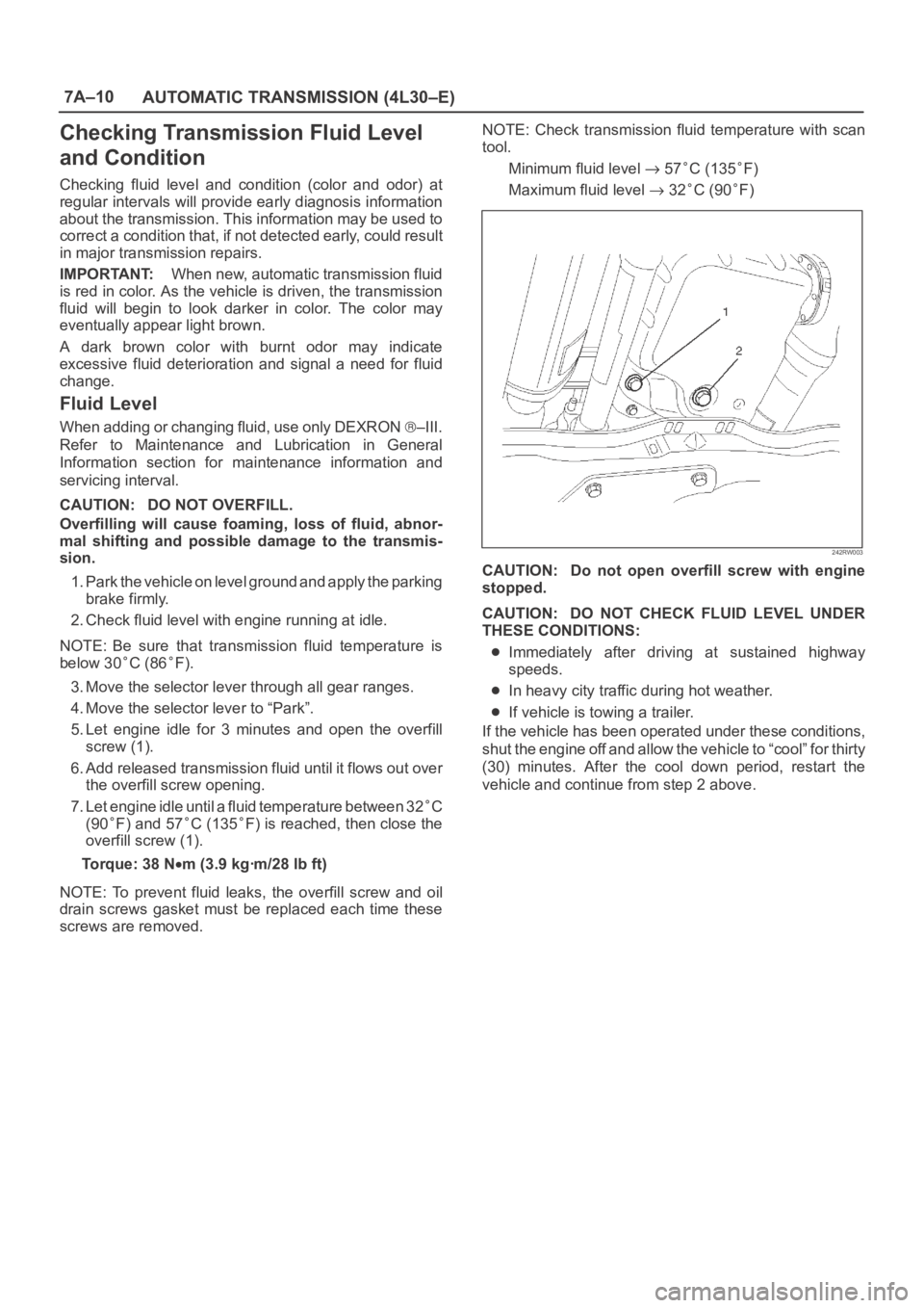
5. Let engine idle for 3 minutes and open the overfill
screw (1).
6. Add released transmission fluid until it flows out over
the overfill screw opening.
7. Let engine idle until a fluid temperature between 32
C
(90
F) and 57C (135F) is reached, then close the
overfill screw (1).
Torque: 38 N
m (3.9 kgꞏm/28 lb ft)
NOTE: To prevent fluid leaks, the overfill screw and oil
drain screws gasket must be replaced each time these
screws are removed.NOTE: Check transmission fluid temperature with scan
tool.
Minimum fluid level
57C (135F)
Maximum fluid level
32C (90F)
242RW003
CAUTION: Do not open overfill screw with engine
stopped.
CAUTION: DO NOT CHECK FLUID LEVEL UNDER
THESE CONDITIONS:
Immediately after driving at sustained highway
speeds.
In heavy city traffic during hot weather.
If vehicle is towing a trailer.
If the vehicle has been operated under these conditions,
shut the engine off and allow the vehicle to “cool” for thirty
(30) minutes. After the cool down period, restart the
vehicle and continue from step 2 above.
Page 2181 of 6000
7A–27 AUTOMATIC TRANSMISSION (4L30–E)
Changing Transmission Fluid
There is no need to change the transmission fluid unless
the transmission is used under one or more of the
following heavy duty conditions.
A. Repeated short trips
B. Driving on rough roads
C. Driving on dusty roads
D. Towing a trailer
If the vehicle is used under these conditions, change the
fluid every 20,000 miles (32,000 km.)
More over, the remaining life percentage of ATF can be
estimated by using Tech 2 as an auxiliary tool to judge the
right time for ATF replacement.
The remaining life percentage is calculated from ATF’S
heat history. When it is close to 0%, ATF replacement is
recommended.
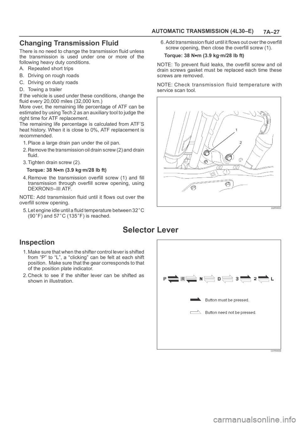
1. Place a large drain pan under the oil pan.
2. Remove the transmission oil drain screw (2) and drain
fluid.
3. Tighten drain screw (2).
Torque: 38 N
m (3.9 kgꞏm/28 lb ft)
4. Remove the transmission overfill screw (1) and fill
transmission through overfill screw opening, using
DEXRON
–III ATF.
NOTE: Add transmission fluid until it flows out over the
overfill screw opening.
5. Let engine idle until a fluid temperature between 32
C
(90
F) and 57C (135F) is reached.6. Add transmission fluid until it flows out over the overfill
screw opening, then close the overfill screw (1).
To r q u e : 3 8 N
m (3.9 kgꞏm/28 lb ft)
NOTE: To prevent fluid leaks, the overfill screw and oil
drain screws gasket must be replaced each time these
screws are removed.
NOTE: Check transmission fluid temperature with
service scan tool.
242RW003
Selector Lever
Inspection
1. Make sure that when the shifter control lever is shifted
from “P” to “L”, a “clicking” can be felt at each shift
position. Make sure that the gear corresponds to that
of the position plate indicator.
2. Check to see if the shifter lever can be shifted as
shown in illustration.
C07RW009
Page 2270 of 6000
TRANSMISSION CONTROL SYSTEM (4L30–E)7A1–25
DTC P0218 Transmission Fluid Over Temperature
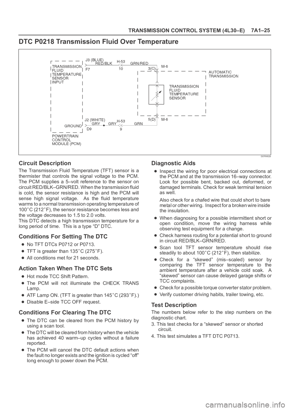
D07RW029
Circuit Description
The Transmission Fluid Temperature (TFT) sensor is a
thermister that controls the signal voltage to the PCM.
The PCM supplies a 5–volt reference to the sensor on
circuit RED/BLK–GRN/RED. When the transmission fluid
is cold, the sensor resistance is high and the PCM will
sense high signal voltage. As the fluid temperature
warms to a normal transmission operating temperature of
100
C (212F), the sensor resistance becomes less and
the voltage decreases to 1.5 to 2.0 volts.
This DTC detects a high transmission temperature for a
long period of time. This is a type “D” DTC.
Conditions For Setting The DTC
No TFT DTCs P0712 or P0713.
TFT is greater than 135C (275F).
All conditions met for 21 seconds.
Action Taken When The DTC Sets
Hot mode TCC Shift Pattern.
The PCM will not illuminate the CHECK TRANS
Lamp.
ATF Lamp ON. (TFT is greater than 145C (293F).)
Disable E–side TCC OFF request.
Conditions For Clearing The DTC
The DTC can be cleared from the PCM history by
using a scan tool.
The DTC will be cleared from history when the vehicle
has achieved 40 warm–up cycles without a failure
reported.
The PCM will cancel the DTC default actions when
the fault no longer exists and the ignition is cycled “off”
long enough to power down the PCM.
Diagnostic Aids
Inspect the wiring for poor electrical connections at
the PCM and at the transmission 16–way connector.
Look for possible bent, backed out, deformed, or
damaged terminals. Check for weak terminal tension
as well.
Also check for a chafed wire that could short to bare
metal or other wiring. Inspect for a broken wire inside
the insulation.
When diagnosing for a possible intermittent short or
open condition, move the wiring harness while
observing test equipment for a change.
Check harness routing for a potential short to ground
in circuit RED/BLK–GRN/RED.
Scan tool TFT sensor temperature should rise
steadily to about 100
C (212F), then stabilize.
Check for a “skewed” (mis–scaled) sensor by
comparing the TFT sensor temperature to the
ambient temperature after a vehicle cold soak. A
“skewed” sensor can cause delayed garage shifts or
TCC complaints.
Check for a possible torque converter stator problem.
Verify customer driving habits, trailer towing, etc.
Test Description
The numbers below refer to the step numbers on the
diagnostic chart.
3. This test checks for a “skewed” sensor or shorted
circuit.
4. This test simulates a TFT DTC P0713.
Page 2281 of 6000
7A1–36
TRANSMISSION CONTROL SYSTEM (4L30–E)
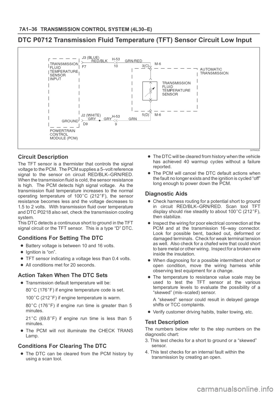
DTC P0712 Transmission Fluid Temperature (TFT) Sensor Circuit Low Input
D07RW029
Circuit Description
The TFT sensor is a thermister that controls the signal
voltage to the PCM. The PCM supplies a 5–volt reference
signal to the sensor on circuit RED/BLK–GRN/RED.
When the transmission fluid is cold, the sensor resistance
is high. The PCM detects high signal voltage. As the
transmission fluid temperature increases to the normal
operating temperature of 100
C (212F), the sensor
resistance becomes less and the voltage decreases to
1.5 to 2 volts. With transmission fluid over temperature
and DTC P0218 also set, check the transmission cooling
system.
This DTC detects a continuous short to ground in the TFT
signal circuit or the TFT sensor. This is a type “D” DTC.
Conditions For Setting The DTC
Battery voltage is between 10 and 16 volts.
Ignition is “on”.
TFT sensor indicating a voltage less than 0.4 volts.
All conditions met for 20 seconds.
Action Taken When The DTC Sets
Transmission default temperature will be:
80
C (176F) if engine temperature code is set.
100
C (212F) if engine temperature is warm.
80
C (176F) if engine run time is greater than 5
minutes.
21
C (69.8F) if engine run time is less than 5
minutes.
The PCM will not illuminate the CHECK TRANS
Lamp.
Conditions For Clearing The DTC
The DTC can be cleared from the PCM history by
using a scan tool.
The DTC will be cleared from history when the vehicle
has achieved 40 warmup cycles without a failure
reported.
The PCM will cancel the DTC default actions when
the fault no longer exists and the ignition is cycled “off”
long enough to power down the PCM.
Diagnostic Aids
Check harness routing for a potential short to ground
in circuit RED/BLK–GRN/RED. Scan tool TFT
display should rise steadily to about 100
C (212F),
then stabilize.
Inspect the wiring for poor electrical connection at the
PCM and at the transmission 16–way connector.
Look for possible bent, backed out, deformed or
damaged terminals. Check for weak terminal tension
as we ll. A lso ch eck fo r a ch af e d w ire th at cou l d s ho r t
to bare metal or other wiring. Inspect for a broken wire
inside the insulation.
When diagnosing for a possible intermittent short or
open condition, move the wiring harness while
observing test equipment for a change.
The temperature to resistance value scale may be
used to test the TFT sensor at the various
temperature levels to evaluate the possibility of a
“skewed” (mis–scaled) sensor.
A “skewed” sensor could result in delayed garage
shifts or TCC complaints.
Verify customer driving habits, trailer towing, etc.
Test Description
The numbers below refer to the step numbers on the
diagnostic chart:
3. This test checks for a short to ground or a “skewed”
sensor.
4. This test checks for an internal fault within the
transmission by creating an open.
Page 2744 of 6000
5.0
W3.0
W FL-1 80A
MAIN
F-8 20A
FRT FOGF-12 15A
TAIL ILLUMI
TAIL
RELAY
BATT.(+)
3
X-9
2X-9
0.85
R/B
0.85
G/R
0.3
BR/R
0.3
BR/R0.3
G
0.3
G
0.3
G
COMBINATION
SWITCH(8) 4
3
X-91
X-9
REAR
FOG
LIGHT
RELAYREAR
FOG
LIGHT
-LH
X-22
X-22
X-22
H-27
X-22
H-15 1.25
BR/Y1.25
Y/R3.0
Y/R
0.85
BR/Y
1.25
BR/Y1.25
BR/Y0.5
BR/Y 1441 2
ABCD
A
1.25
BR/Y1.25
BR/Y0.5
BR/Y
1.25
BR/Y 1.25
BR/YB
R-133
R-13
1
1.25
B1.25
B
1.25
B 1.25
B
REAR
FOG
LIGHT
-RHR-123
R-12
1
TRAILER
HARNESS
CONNECTORH-442
H-338
H-44
4
H-3320
R-4
BODY-RR
11H-13
E
3H-15
H-4641
REAR
FOG
LIGHT
INDI-
CATOR
(METER)
LIGHTING
SW
CDE
I-10
B-12 10
B-391B-393
B-39
DIODE
2
7
H-2720
I-9
30
0.3
B
0.3
L
0.5
B
1.25
B 1.25
B
B-19
BODY-RH
1.25
B
B-122
D08RWA00
Page 2755 of 6000

0.85
G/R
0.85
O/B
0.85
O/B
0.85
O/B
1.25
B/L
1.25
B/L 1.25
B/L
1.25
B
1.25
B1.25
B
LICENSE
PLATE
LIGHT
-RH TAIL
LIGHT
-RH
(BUMPER) TRAILER
HARNESS
CONNECTOR
(TAIL LIGHT)
2
B
F-84
F-817
H-33
0.85
G/R 0.85
G/O
18H-33
R-4
BODY-RR4
H-44
20
H-331
H-44 0.85
G/R
6H-44
2
F-101
F-10
LICENSE
PLATE
LIGHT
-LHTAIL
LIGHT
-LH
(BUMPER)
2
A
F-7
6
H-334
F-7
2
F-91
F-9
D08RWB46
Page 2789 of 6000
1.25
B
1.25
B 1.25
B
1.25
B1.25
B
0.5
B0.5
B
RR TURN
SIGNAL
LIGHT-RH
(BUMPER)FRT TURN
SIGNAL
LIGHT-RHSIDE TURN
SIGNAL
LIGHT-RH
0.85
P/B
C-313
1
1
C-311
H-7
0.85
P/B 0.85
P/B0.85
P/B
C-611
2
C-61
B
7
H-15
C-167C-39
FENDER-LH FENDER-RH FENDER-LH
A
C-701
C-70
2
C-223
C-22
1
H-714H-719
C-16 0.5
B
SIDE TURN
SIGNAL
LIGHT-LHFRT TURN
SIGNAL
LIGHT-LH
0.5
B 0.85
G/B 0.85
G/B 0.85
G/B0.85
G/B
0.85
G/O
0.85
G/O0.85
P/L
0.85
P/L 0.85
G/BTURN SIGNAL
INDICATOR
LIGHT
(METER)
TRAILER HARNESS
CONNECTOR
8
C-16
FENDER-LH1
F-71
H-3221
H-3311
F-7
H-332
F-81
F-8
2
6RR TURN
SIGNAL
LIGHT-LH
(BUMPER)
0.85
G/B0.85
P/B
0.85
P/B
H-3222
H-335
H-44
4
H-591
H-443
H-3320
H-592
H-447
0.85
P/B
R-4
BODY-RR
D08RWC66