Page 732 of 6000
TRANSFER CASE (STANDARD TYPE)
4D1–11
Transfer Rear Cover Assembly (4WD Switch Model)
Transfer Rear Cover Assembly and Associated Parts
220RW102
Legend
(1) Speedometer Sensor, Speedometer Driven
Gear and Plate
(2) Front Companion Flange
(3) Rear Companion Flange(4) Control Box Assembly
(5) 2WD–4WD Actuator Heat Protector
(6) 2WD–4WD Actuator Assembly
(7) Transfer Rear Cover Assembly
(8) Transfer Case Assembly
Page 733 of 6000

4D1–12
TRANSFER CASE (STANDARD TYPE)
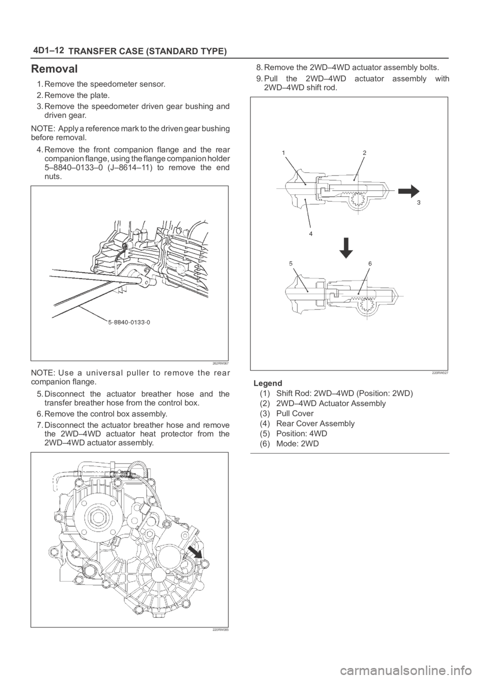
Removal
1. Remove the speedometer sensor.
2. Remove the plate.
3. Remove the speedometer driven gear bushing and
driven gear.
NOTE: Apply a reference mark to the driven gear bushing
before removal.
4. Remove the front companion flange and the rear
companion flange, using the flange companion holder
5–8840–0133–0 (J–8614–11) to remove the end
nuts.
262RW067
NOTE: Use a universal puller to remove the rear
companion flange.
5. Disconnect the actuator breather hose and the
transfer breather hose from the control box.
6. Remove the control box assembly.
7. Disconnect the actuator breather hose and remove
the 2WD–4WD actuator heat protector from the
2WD–4WD actuator assembly.
220RW085
8. Remove the 2WD–4WD actuator assembly bolts.
9. Pull the 2WD–4WD actuator assembly with
2WD–4WD shift rod.
220RW027
Legend
(1) Shift Rod: 2WD–4WD (Position: 2WD)
(2) 2WD–4WD Actuator Assembly
(3) Pull Cover
(4) Rear Cover Assembly
(5) Position: 4WD
(6) Mode: 2WD
Page 735 of 6000

4D1–14
TRANSFER CASE (STANDARD TYPE)
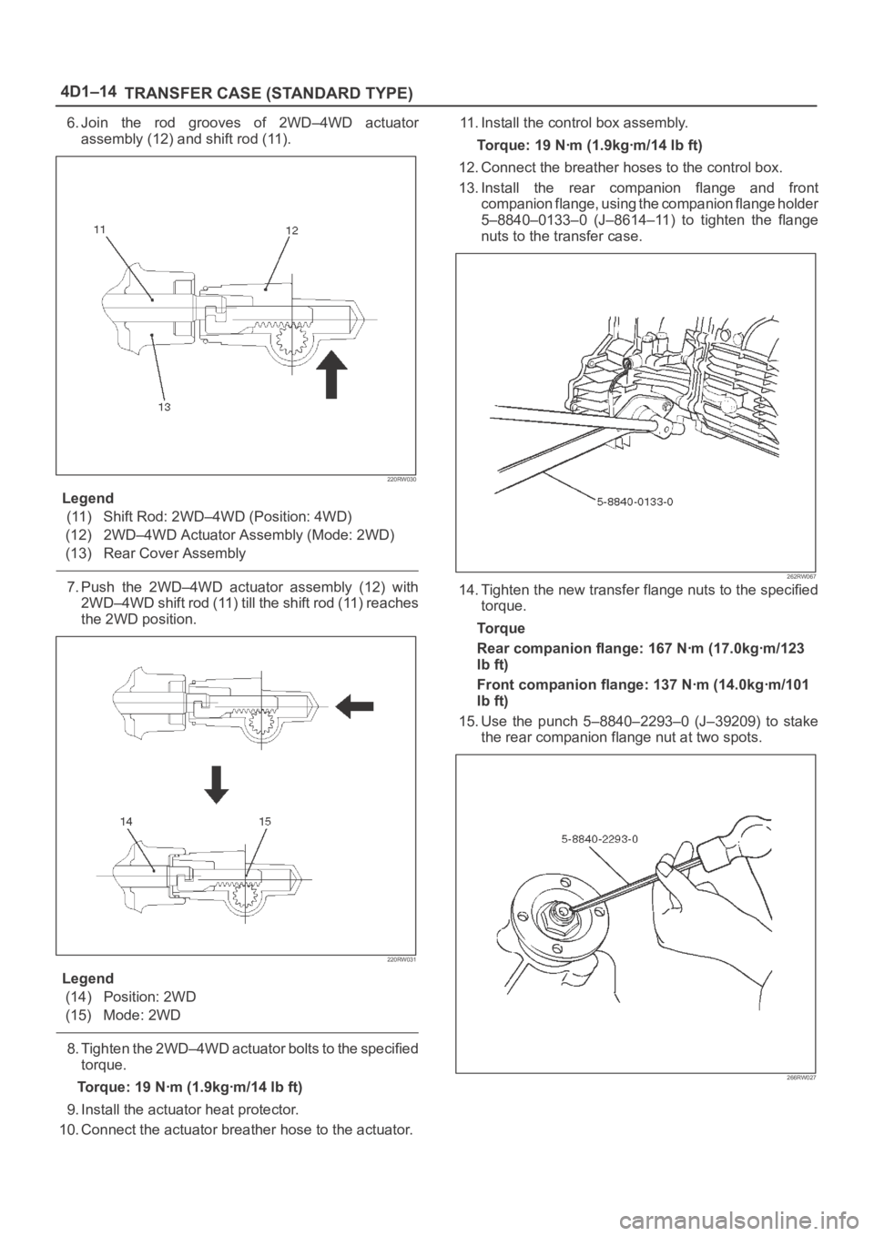
6. Join the rod grooves of 2WD–4WD actuator
assembly (12) and shift rod (11).
220RW030
Legend
(11) Shift Rod: 2WD–4WD (Position: 4WD)
(12) 2WD–4WD Actuator Assembly (Mode: 2WD)
(13) Rear Cover Assembly
7. Push the 2WD–4WD actuator assembly (12) with
2WD–4WD shift rod (11) till the shift rod (11) reaches
the 2WD position.
220RW031
Legend
(14) Position: 2WD
(15) Mode: 2WD
8. Tighten the 2WD–4WD actuator bolts to the specified
torque.
Torque: 19 Nꞏm (1.9kgꞏm/14 lb ft)
9. Install the actuator heat protector.
10. Connect the actuator breather hose to the actuator.11. Install the control box assembly.
Torque: 19 Nꞏm (1.9kgꞏm/14 lb ft)
12. Connect the breather hoses to the control box.
13. Install the rear companion flange and front
companion flange, using the companion flange holder
5–8840–0133–0 (J–8614–11) to tighten the flange
nuts to the transfer case.
262RW067
14. Tighten the new transfer flange nuts to the specified
torque.
To r q u e
Rear companion flange: 167 Nꞏm (17.0kgꞏm/123
lb ft)
Front companion flange: 137 Nꞏm (14.0kgꞏm/101
lb ft)
15. Use the punch 5–8840–2293–0 (J–39209) to stake
the rear companion flange nut at two spots.
266RW027
Page 740 of 6000
TRANSFER CASE (STANDARD TYPE)
4D1–19
Transfer Rear Cover Assembly (Except 4WD Switch Model)
Transfer Rear Cover Assembly and Associated Parts
220RW116
Legend
(1) Speedometer Sensor, Speedometer Driven
Gear and Plate
(2) Front Companion Flange(3) Rear Companion Flange
(4) Control Box Assembly
(5) Transfer Rear Cover Assembly
(6) Transfer Case Assembly
Page 741 of 6000

4D1–20
TRANSFER CASE (STANDARD TYPE)
Removal
1. Remove the speedometer sensor.
2. Remove the plate.
3. Remove the speedometer driven gear bushing and
driven gear.
NOTE: Apply a reference mark to the driven gear bushing
before removal.
4. Remove the front companion flange and the rear
companion flange, using the flange companion holder
5–8840–0133–0 (J–8614–11) to remove the end
nuts.
262RW067
NOTE: Use a universal puller to remove the rear
companion flange.
5. Disconnect the transfer breather hose from the
control box.
6. Remove the control box assembly.
7. Remove the transfer rear cover assembly from the
transfer case assembly.
Installation
1. Apply the recommended liquid gasket (LOCTITE
17430) or its equivalent to the transfer rear cover
fitting faces.
220RS017
2. Install the transfer rear cover assembly to the transfer
case assembly.
3. Perform the following steps before fitting the transfer
rear case:
1. Shift the high–low shift rod to the 4H side.
2. Turn the select rod counterclockwise so that the
select block projection may enter into the
2WD–4WD shift block.
3. The cut–away portion of the select rod head (9)
should align with that of the rear case hole’s
stopper (10).
230RW004
4. Tighten the transfer rear case bolts to the specified
torque.
Torque: 37 Nꞏm (3.8kgꞏm/27 lb ft)
Page 742 of 6000

TRANSFER CASE (STANDARD TYPE)
4D1–21
5. Install the control box assembly.
Torque: 19 Nꞏm (1.9kgꞏm/14 lb ft)
6. Connect the breather hoses to the control box.
7. Install the rear companion flange and front
companion flange, using the companion flange holder
5–8840–0133–0 (J–8614–11) to tighten the flange
nuts to the transfer case.
262RW067
8. Tighten the new transfer flange nuts to the specified
torque.
Torque
Rear companion flange: 167 Nꞏm (17.0kgꞏm/123
lb ft)
Front companion flange: 137 Nꞏm (14.0kgꞏm/101
lb ft)
9. Use the punch 5–8840–2293–0 (J–39209) to stake
the rear companion flange nut at two spots.
266RW027
266RW002
10. Stake the front companion flange nut at one spot.
NOTE: Be sure to confirm that there is no crack at the
staked portion of the flange nut after staking.
11. Install the O–ring (8) to the speedometer driven gear
bushing (7).
12. Install the driven gear to the speedometer driven gear
bushing (7).
13. Install the speedometer driven gear assembly to the
transfer rear cover.
14. Install the plate (6) to the transfer rear case and
tighten to the specified torque.
Torque: 15 Nꞏm (1.5kgꞏm/11 lb ft)
Page 2322 of 6000

7B–4MANUAL TRANSMISSION
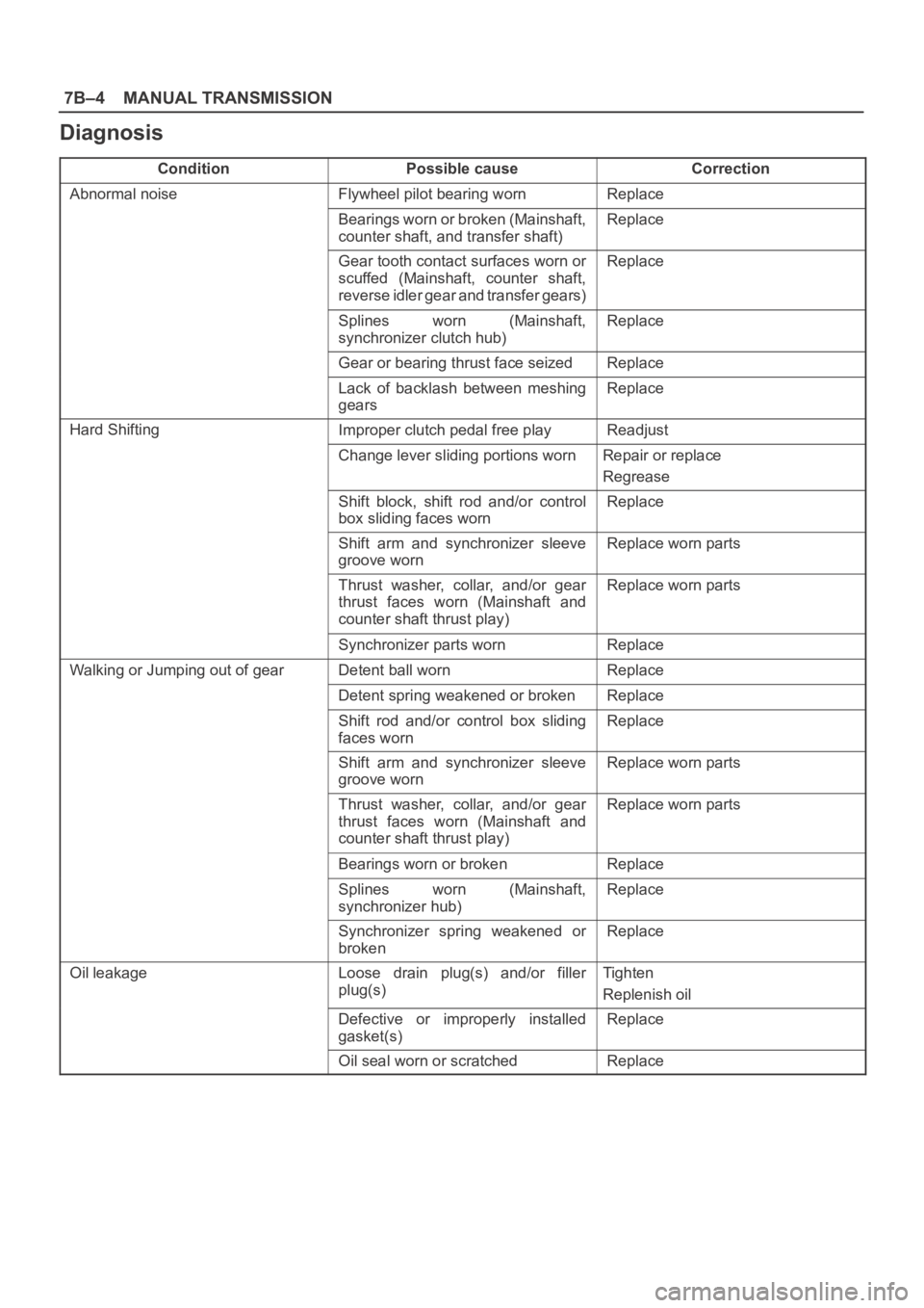
Diagnosis
ConditionPossible causeCorrection
Abnormal noiseFlywheel pilot bearing wornReplace
Bearings worn or broken (Mainshaft,
counter shaft, and transfer shaft)Replace
Gear tooth contact surfaces worn or
scuffed (Mainshaft, counter shaft,
reverse idler gear and transfer gears)Replace
Splines worn (Mainshaft,
synchronizer clutch hub)Replace
Gear or bearing thrust face seizedReplace
Lack of backlash between meshing
gearsReplace
Hard ShiftingImproper clutch pedal free playReadjust
Change lever sliding portions wornRepair or replace
Regrease
Shift block, shift rod and/or control
box sliding faces wornReplace
Shift arm and synchronizer sleeve
groove wornReplace worn parts
Thrust washer, collar, and/or gear
thrust faces worn (Mainshaft and
counter shaft thrust play)Replace worn parts
Synchronizer parts wornReplace
Walking or Jumping out of gearDetent ball wornReplace
Detent spring weakened or brokenReplace
Shift rod and/or control box sliding
faces wornReplace
Shift arm and synchronizer sleeve
groove wornReplace worn parts
Thrust washer, collar, and/or gear
thrust faces worn (Mainshaft and
counter shaft thrust play)Replace worn parts
Bearings worn or brokenReplace
Splines worn (Mainshaft,
synchronizer hub)Replace
Synchronizer spring weakened or
brokenReplace
Oil leakageLoose drain plug(s) and/or filler
plug(s)Tighten
Replenish oil
Defective or improperly installed
gasket(s)Replace
Oil seal worn or scratchedReplace
Page 2338 of 6000
7B–20MANUAL TRANSMISSION
220RW095
Legend
(1) Release Bearing and Shift Fork
(2) Clutch Housing
(3) Front Cover
(4) Snap Ring
(5) Snap Ring
(6) 1st and 2nd Switch
(7) Drain Plug
(8) Backup Light Switch
(9) Transmission Case(10) Filler Plug
(11) Gear Control Rod
(12) Reverse Restrict Pin
(13) Oil Receiver Pipe
(14) Transfer Adapter
(15) Plug (6VE1) or Neutral Switch (4JX1)
(16) Gear Control Box
(17) Shift Lever Housing
(18) Oil Seal
(19) Plug